Advertisement
Johnson Controls MS-NAE5520-0
Network Engine
A l l t r a d e m a r k s , b r a n d n a m e s , a n d b r a n d s a p p e a r i n g h e r e i n a r e t h e p r o p e r t y o f t h e i r r e s p e c t i v e o w n e r s .
• C r i t i c a l a n d e x p e d i t e d s e r v i c e s
• I n s t o c k / R e a d y - t o - s h i p
Artisan Scientific Corporation dba Artisan Technology Group is not an affiliate, representative, or authorized distributor for any manufacturer listed herein.
$
1995
.00
In Stock
Qty Available: 2
Used and in Excellent Condition
Open Web Page
https://www.artisantg.com/75025-2
• We b u y y o u r e x c e s s , u n d e r u t i l i z e d , a n d i d l e e q u i p me n t
• F u l l - s e r v i c e , i n d e p e n d e n t r e p a i r c e n t e r
Advertisement
Table of Contents

Related Manuals for Johnson Controls MS-NAE55 Series


Summary of Contents for Johnson Controls MS-NAE55 Series
- Page 1 Johnson Controls MS-NAE5520-0 Network Engine 1995 In Stock Qty Available: 2 Used and in Excellent Condition Open Web Page https://www.artisantg.com/75025-2 A l l t r a d e m a r k s , b r a n d n a m e s , a n d b r a n d s a p p e a r i n g h e r e i n a r e t h e p r o p e r t y o f t h e i r r e s p e c t i v e o w n e r s .
-
Page 2: Installation Instructions
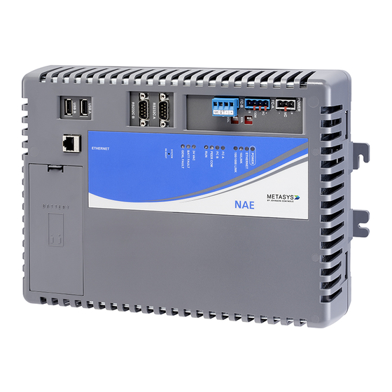
NAE55/NIE55 Installation Instructions Part No. 24-10051-35, Rev. A MS-NAE55xx-x Release 3.1 Europe MS-NIE55xx-x Issued January 10, 2012 Supersedes June 4, 2008 Application • Do not drop the NAE55 or subject it to physical shock. The Network Automation Engine (NAE) and Network Integration Engine (NIE) are Web-enabled, •... - Page 3 FC Bus (N2 Trunk, 6-Pin Modular RS-232-C FC Bus) 24 VAC ORKS Terminals Modem Serial Ports Terminal Power Terminal Jack Ports End-of-Line (EOL) Switches RJ-45 8-Pin Ethernet Jack Wall Mount Data Feet Protection Battery Compartment System Status 226 mm Light-Emitting Diodes (8.9 in.) (LEDs) System...
- Page 4 Mounting the NAE55/NIE55 Wall Mount Applications To mount the NAE55 on a vertical surface: 1. Mark the location of the four holes (for the wall mount feet) on the wall using the dimensions in Figure 3 and according to an orientation in Figure 4.
- Page 5 Power Supply Computer Serial Ports IMPORTANT: Install the data protection battery IMPORTANT: Do not use computer serial ports in before applying 24 VAC power to the NAE55. See normal product operation for UL 864 Listed smoke the Installing the Data Protection Battery section. control applications.
- Page 6 If the American Power Conversion (APC®) • Route the supply power wires and communication ProtectNet® model PNET1 Ethernet/token ring port cables at least 50 mm (2 in.) away from the vent surge protector is necessary as described in the slots in the sides of the NAE55 housing. Metasys System Extended Architecture Smoke Control •...
- Page 7 Network Terminal Block ORKS Note: Power supply wire colors may be different on and Wiring Connections transformers not manufactured by Johnson Controls. Follow the transformer manufacturer’s instructions and 4. Make connections to the RS-232 serial ports (if the project installation drawings.
- Page 8 Table 2: Guidelines for BACnet Protocol MS/TP Network Topology Category Rules/Maximums Allowed General MS-NAE55xx-x models (only) support up to two MS/TP Bus trunks, daisy chain topology only. Number of Devices devices per FC Bus with no more than two repeaters between NAE55 and any device and a maximum of 50 devices between repeaters Line Length and Type 1,500 m (5,000 ft) cable without a repeater...
-
Page 9: Setup And Adjustments
Table 6: Maximum Number of Devices per L Network Segment ORKS Device Type Maximum Allowed FTT-10 Nodes Only 64 (if repeaters are not used) FTT-10 Nodes Only 128 (if repeaters are used) ([FTT10 x 2] + LPT10) < 128 Mixed FTT-10 and LPT-10 Nodes Physical Layer Repeaters Maximum of 1 per segment Terminators... -
Page 10: Troubleshooting
Setting the End-of-Line Switches When the 24 VAC supply power to the NAE55 is disconnected or lost, the NAE55 is nonoperational. The The network devices at each end of an FC Bus POWER LED (Figure 11) remains On, and the data segment must be set as network terminated devices. - Page 11 The total time to start up the NAE55 depends on the Press the System Re-Boot switch only if the NAE55 size of the database and can take several minutes. fails to respond and cannot be accessed by any user device. Do not press the System Re-Boot switch System Re-Boot Switch unless you have tried other reasonable means to fix the The System Re-Boot switch (Figure 1) forces a manual...
-
Page 12: Repair Information
Repair Information Refer to the Replacing an NAE section in the NAE Commissioning Guide (LIT-1201519) for information on If you replace an NAE for any reason or add a new replacing an NAE and configuring the new NAE to NAE to a site, you must update the site registration to communicate in a Metasys system site. -
Page 13: Technical Specifications
Technical Specifications NAE55 and NIE55 (Part 1 of 2) Power Requirement Dedicated nominal 24 VAC, Class 2 power supply (North America), Safety Extra-Low Voltage (SELV) power supply (Europe), at 50/60 Hz (20 VAC minimum to 30 VAC maximum) Power Consumption 50 VA maximum Ambient Operating 0–50°C (32–122°F);... - Page 14 The performance specifications are nominal and conform to acceptable industry standard. For application at conditions beyond these specifications, consult the local Johnson Controls® office. Johnson Controls, Inc. shall not be liable for damages resulting from misapplication or misuse of its products.
Need help?
Do you have a question about the MS-NAE55 Series and is the answer not in the manual?
Questions and answers