Table of Contents
Advertisement
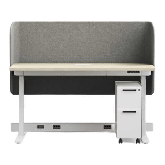
A8
Installation Instructions
Index
. . . . . . . . . . . . . . . . . . . . . . 2
Table Assembly
. . . . . . . . . . . . . . . . . . . . . . . 3
Leg and Foot . . . . . . . . . . . . . . . . . . . . . . . . . . . . . . . 3
Utility Bay End Caps . . . . . . . . . . . . . . . . . . . . . . . . . 3
Utility Bay Latch Rail . . . . . . . . . . . . . . . . . . . . . . . . . 5
Control Box and Height Adjustable Control . . . . . . . . 5
Utility Bay . . . . . . . . . . . . . . . . . . . . . . . . . . . . . . . . . . 5
Grommet . . . . . . . . . . . . . . . . . . . . . . . . . . . . . . . . . . 6
Power Module . . . . . . . . . . . . . . . . . . . . . . . . . . . . . . 6
Wire Management . . . . . . . . . . . . . . . . . . . . . . . . . . . 7
Screen Assembly
Screen Assembly . . . . . . . . . . . . . . . . . . . . . . . . . . . . 8
. . . . . . . . . . . . . . . . . . . . . . . . . . . . 10
Power Rail Foot . . . . . . . . . . . . . . . . . . . . . . . . . . . . 10
Optional Floor Anchor . . . . . . . . . . . . . . . . . . . . . . . 10
End of Rail . . . . . . . . . . . . . . . . . . . . . . . . . . . . . . . . 10
"T", "L", and "X" Connections . . . . . . . . . . . . . . . . . . 11
Inline Connection . . . . . . . . . . . . . . . . . . . . . . . . . . . 11
Electrical and Data . . . . . . . . . . . . . . . . . . . . . . . . . 12
Finishing . . . . . . . . . . . . . . . . . . . . . . . . . . . . . . . . . 12
Hardwire Power In-feed . . . . . . . . . . . . . . . . . . . . . . 13
Electrical Circuits . . . . . . . . . . . . . . . . . . . . . . . . . . . 14
Pour des instructions en francias, appelar le 800-822-7653
Para instrucciones en enspanol, llame al 800-822-7653
. . . . . . . . . . . . . . . . . . . . . 8
Tools Needed
#2 Phillips Driver
#3 Phillips Driver
4mm Allen Driver
1/4" Socket or Driver Bit
5/16" Socket or Driver Bit
3/8" Socket or Driver Bit
T20 Driver Bit
3430450000 E
Drill
Advertisement
Table of Contents

Related Manuals for Allsteel A8


Summary of Contents for Allsteel A8
-
Page 1: Table Of Contents
Index A8 Parts Outline . . . . . . . . . . . . . . . . . . . . . . 2 Table Assembly . -
Page 2: A8 Parts Outline
Installation Packet A8 Parts Outline Control Box Worksurface Bracket Table Foot Worksurface Height Adjustable Column Latch Rail Energy Chain Bracket Utility Bay End Cap Utility Bay End Cap Grommet Dual Lock Power Module Utility Bay Energy Chain & Clip Column Wire Manager... - Page 3 Installation Packet Leg and Foot Assembly 6 - Attach end cap with 5/16” socket screws; each end cap requires two (2) screws . 7 - Attach foot to leg column; each leg requires four (4) 4mm hex screws . 8 - Attach glides or casters . Glides thread directly into foot . Casters attach with four (4) 5/16”...
- Page 4 Installation Packet Leg and Foot Assembly Leg and Foot Assembly 1 - Slide worksurface bracket over motor in orientation shown . 2 - Attach worksurface bracket with four (4) 4mm hex screws . 3 - Attach Energy Chain Clip(included with Energy Chain Model FDCLWMC) to Energy Chain Bracket with two(2) #8 flat head screws(included in hardware pack sent with Energy Chain Model)
- Page 5 Installation Packet Utility Bay Assembly Align with locator holes 1 - Using locator holes as alignment, attach the latch rail with six (6) #3 drive Phillips screws as shown . Note: The holes closest to the bend will align with the locator holes .
- Page 6 Installation Packet Grommet and Power Module 1 - Orient the grommet with the hinge toward the rear of the worksurface . Press grommet assembly into worksurface . 2 - Power modules come standard with Dual Lock . Place Dual Lock on the back of the power module and adhere to the back of the center utility bay .
-
Page 7: Wire Management
Installation Packet Wire Management 1 - Route the wires through the utility bay end cap . Note: The wires can be routed through either the RH or LH side, per furniture layout (RH exit shown) . 2 - Route the wires up through the top of the column wire manager, down the back of the column wire manager, and out the bottom of the column wire manager as shown . - Page 8 Installation Packet Screen Attachment Step 1 1 - Set screen on clean flat working surface. Step 2 2 - Remove placeholder brackets and replace with L-brackets . Use a #3 Phillips drive for steps 2a-2d . 2a - Remove first placeholder bracket. 2b - Replace with first L-bracket, using the same holes and screws .
- Page 9 Installation Packet Screen Attachment Step 4 4 - Smooth out fabric with clean hands . 4a - Ensure seams are located on edges, as shown . 4b - Flatten out wrinkles from handling . 4c - Ensure fabric tension is even throughout the screen . Check that bridge over wing is consistent . ü...
-
Page 10: Power Rail
Installation Packet Power Rail Foot Attachment 1 - Slide foot into the slot in the orientation shown . 2 - Select a desired height . Note: Each foot provides 2 inches of leveling . 3 - Attach the feet with two (2) 3/8” socket screws . -
Page 11: T", "L", And "X" Connections
Installation Packet Power Rail “T”, “L”, and “X” Connections 1 - Place the universal connector assembly between the lower rail housings that are to be connected . 2 - Align the connector brackets to the mounting holes in the lower housing and the universal connector . -
Page 12: Electrical And Data
Installation Packet Power Rail Electrical/Data 1 - Insert duplexes into the power harness . 2 - Slide the power blocks into the electrical brackets . Note: The upper housings must have at least one duplex . 3 - Connect the power harnesses together and to in-feed as necessary . - Page 13 Installation Packet Power Rail with New York Infeed 24” wide pass through A8 Beam End Infeed with power block New York Junction Box Power Whip Entry A8 Beam End Infeed 1 - Same kit regardless of beam length . Order 4 circuit or 3 circuit depending on requirements 2 - Slide Beam End Cap on Power Whip before wiring to New York Junction Box 3 - Install 24”...
- Page 14 To prevent personal injury ensure all power sources are disconnected during installation. electrical needs change. Four‑circuit, 3 + 1 Receptacle Option The 3 + 1 option is the electrical standard used on Allsteel systems for many years in most installations. This wiring option provides three utility circuits plus an isolated/dedicated circuit for more sensitive equipment.
Need help?
Do you have a question about the A8 and is the answer not in the manual?
Questions and answers