
Related Manuals for Broadcom Emulex LPe31000-Series


Summary of Contents for Broadcom Emulex LPe31000-Series
- Page 1 Emulex LPe31000-Series and LPe32000-Series Adapters Installation Guide Versions 11.0 and 11.1 April 29, 2016 pub-005608...
-
Page 2: April
Broadcom Ltd. and/or its affiliates in the United States, certain other countries and/or the EU. Any other trademarks or trade names mentioned are the property of their respective owners. Broadcom Ltd. reserves the right to make changes without further notice to any products or data herein to improve reliability, function, or design. -
Page 3: Table Of Contents
Emulex LPe31000-Series and LPe32000-Series Adapters Installation Guide Table of Contents April 29, 2016 Table of Contents Chapter 1: Introduction ......................4 1.1 Overview . -
Page 4: Chapter 1: Introduction
Changing the Speed of the Adapter. The core technology of these adapters is Broadcom's 6th generation FC controller. The controller is a multi-function PCIe Gen3 interface controller that is compliant to the PCI Express Base Specification Rev 3.0 and PCI Express CEM Specification Rev 3.0. -
Page 5: Compatibility
Use PCIe Gen 3 compliant systems that are x8 or x16 lane at up to 8 GTps per lane. 1.1.4 Adapter Identification Each adapter ships with several numbers clearly marked on the board. Broadcom recommends recording these numbers before installation. Serial number – assigned by Broadcom. Use this number when communicating with Broadcom. -
Page 6: Chapter 2: Installation
The standard adapters can be connected to fiber optic cables. Preparing the Adapter for Installation The Broadcom Emulex LPe31000-series and LPe32000-series adapters use removable optical transceivers. If you need to change the bracket for an adapter installation, you must first remove the optical transceiver(s), if installed, from the housing (cage). - Page 7 Emulex LPe31000-Series and LPe32000-Series Adapters Installation Guide Chapter 2: Installation April 29, 2016 Preparing the Adapter for Installation Figure 2 shows a transceiver with the latch released (bail extended) and another transceiver latched in place. Figure 2 Releasing the Latch on an Optical Transceiver Figure 3 shows an extracted transceiver and another transceiver latched in place.
-
Page 8: Installing The Adapter
Emulex LPe31000-Series and LPe32000-Series Adapters Installation Guide Chapter 2: Installation April 29, 2016 Installing the Adapter Remove the mounting bracket screws from the top of the adapter. Figure 4 shows the screws that are removed from the bracket. Figure 4 Removing the Bracket Remove the bracket and store it for future use. -
Page 9: Attaching Media
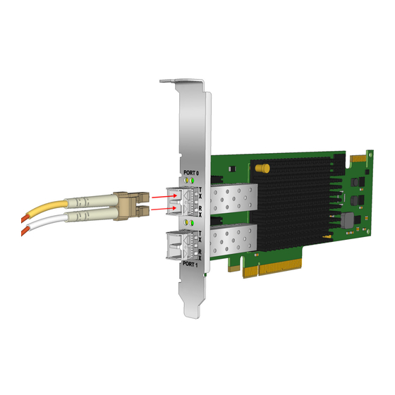
Emulex LPe31000-Series and LPe32000-Series Adapters Installation Guide Chapter 2: Installation April 29, 2016 Attaching Media Insert the adapter into an empty PCIe x8 or x16 slot. Press firmly until the adapter is seated. NOTE Make sure that the adapter is in an appropriate PCIe slot that does not interfere with other components or with the case to prevent damage to the adapter. - Page 10 Emulex LPe31000-Series and LPe32000-Series Adapters Installation Guide Chapter 2: Installation April 29, 2016 Attaching Media To attach media to the adapter: Connect the appropriate cable to the adapter. When connecting an optical cable, ensure that the cages have optical transceivers installed in them (see...
-
Page 11: Broadcom Lightpulse Accessories
SFP+ LP32-SW-OPT-2 LP, 32GFC, SW, SFP+, OptTcvr, 2pc SFP+ NOTE Only Broadcom accessories are warranted and fully supported by Broadcom technical support. Applying Power To apply power: Verify that the adapter is securely installed in the system. Verify that the correct media is attached. -
Page 12: Viewing The Leds
Emulex LPe31000-Series and LPe32000-Series Adapters Installation Guide Chapter 2: Installation April 29, 2016 Viewing the LEDs Viewing the LEDs You can view the green and yellow LEDs through openings in the adapter's mounting bracket. The green LED indicates firmware operation and the yellow LED indicates port activity or link speed. Each port has a corresponding... -
Page 13: Changing The Speed Of The Adapter
Emulex LPe31000-Series and LPe32000-Series Adapters Installation Guide Chapter 2: Installation April 29, 2016 Changing the Speed of the Adapter Table 4 POST Conditions and Results (Continued) Green LED Yellow LED State Flashing POST processing in progress Failure in Common Code Module... - Page 14 Emulex LPe31000-Series and LPe32000-Series Adapters Installation Guide Chapter 2: Installation April 29, 2016 Setting the Secure Firmware Jumper The following illustrations (Figure 8 Figure 9) provide an example of common locations of the Secure Firmware jumper. Figure 8 Secure Firmware Jumper Location J2 on LPe31000, LPe31002, LPe32000, and LPe32002 Adapters.
-
Page 15: Chapter 3: References
Emulex LPe31000-Series and LPe32000-Series Adapters Installation Guide Chapter 3: References April 29, 2016 LPe31000-series and LPe32000–Series Adapter Specifications Chapter 3: References LPe31000-series and LPe32000–Series Adapter Specifications The specifications of the LPe31000-series and LPe32000–series adapters are listed in Table Table 5 LPe31000-series and LPe32000–series Adapter Specifications... -
Page 16: Fcc And Regulatory Notices
The reader is cautioned that changes or modifications made to the equipment not expressly approved by Broadcom could void the user's authority to operate this equipment. The above statement applies to products marketed in the USA. -
Page 17: Notice For Taiwan And Translations (Bsmi)
Emulex LPe31000-Series and LPe32000-Series Adapters Installation Guide Chapter 3: References April 29, 2016 FCC and Regulatory Notices 3.2.1.2 Notice for Taiwan and Translations (BSMI) Translation: This equipment is a Class A ITE, and operation of this equipment in a residential area is likely to cause harmful interference, in which case users will be required to correct the interference at their own expense. -
Page 18: Declarations Of Conformity
Emulex LPe31000-Series and LPe32000-Series Adapters Installation Guide Chapter 3: References April 29, 2016 Declarations of Conformity Declarations of Conformity 3.3.1 LPe3x00x DECLARATION OF CONFORMITY Manufacturer: Emulex Corporation 3333 Susan Street Costa Mesa, CA. 92626 USA declares under sole responsibility that the product: Product Name: LightPulse®... -
Page 19: Lpe31004
Emulex LPe31000-Series and LPe32000-Series Adapters Installation Guide Chapter 3: References April 29, 2016 Declarations of Conformity 3.3.2 LPe31004 DECLARATION OF CONFORMITY Manufacturer: Broadcom Limited 3333 Susan Street Costa Mesa, CA. 92626 USA declares under sole responsibility that the product: Product Name: LightPulse®... -
Page 20: Laser Safety Notice
DHHS/CDRH 21CFR Sub-chapter J, and the international laser safety standard EN/IEC 60825-1. Class 1 laser devices are not considered to be hazardous. The use of non-Broadcom approved optical transceivers, or transceivers which do not comply with the Class 1 radiation performance requirements defined in DHHS/CDRH 21CFR Sub-chapter J and IEC 60825-1, may expose the user to hazardous laser radiation, and such devices should not be used with Broadcom products.
Need help?
Do you have a question about the Emulex LPe31000-Series and is the answer not in the manual?
Questions and answers