
Related Manuals for baltur TS 0 GN


Summary of Contents for baltur TS 0 GN
- Page 1 Instruction for industrial dual fuel “Natural gas / Heavy oil burners model TS 0 GN TS 1 GN TS 2 GN TS 3 GN TS 4 GN 2007/07 Edition Cod. 0006080240...
- Page 3 Dichiarazione di Conformità Statement of Conformity Dichiariamo, sotto la Nostra responsabilità, che We hereby declare under our own i Nostri prodotti contrassegnati “CE” responsibility, that our “CE” marked products Serie: Series: Sparkgas…; BTG…; BGN…; Sparkgas…; BTG…; BGN…; Minicomist…; Comist…; RiNOx…, BT…; Minicomist…;...
- Page 4 • Read careffuly the instructions before starting the burner and service it. • The works on the burner and on the system have to be carried out only by competent people. • The system electric feeding must be disconnected before starting working on it. •...
- Page 5 BURNER MODEL “TS” OVERALL DIMENSIONS N° 0002670092 Model ø ø ø ø TS 0 L 1095 TS 1 L 1525 TS 2 L 1515 TS 3 L 1700 TS 4 L 1025 1085 700 2115 560 1040 555 TS 0 N 1095 TS 1 N 1525...
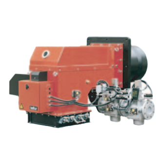
- Page 6 DESCRIPTION “TS” Series INDUSTRIAL BURNERS (stripped head) The “TS” burner consists of separately-supplied units. These must be connected together on the chosen site for the burner in accordance with directions issued by BALTUR. Combustion head Control panel Liquid-fuel pumping unit.
-
Page 7: Electrical Connections
FASTENING THE BURNER TO THE BOILER The burner must be applied to the boiler’s iron plate (with a heat protection flange inserted in-between), where the stud bolts given as standard accessories have already been fitted in accordance with the plate drilling. It is advisable to electrically weld the stud bolts to the internal part of the plate to avoid extracting them together with the unit’s locking nuts, should be burner be disassembled. - Page 8 GAS (METHANE) FEED SYSTEM FROM THE GAS PIPE NETWORK AND AVERAGE PRESSURE (See BT 8530/1 and BT 8531/1) When high delivery is required, the Gas Distributing DIAGRAM FOR CALCULATING THE DIAMETER OF Company requests the installation of a unit comprising a THE PIPES IN RELATION TO THEIR LENGTH AND pressure reducer and a meter, and then connects the N°...
- Page 9 DIAGRAM OF CONNECTING MORE THAN ONE N° 8530-1 BURNER TO THE GAS PIPE NETWORK AT Rev. 15/11/90 AVERAGE PRESSURE 1 - Measuring and reducing unit 2 - Interception 3 - Filter 4 - Reducer 5 - Meter 6 - Emergency interception (installed outside) 7 - Ball cock 8 - Filter 9 - Final reducer or stabilizer...
-
Page 10: Fuel Feed System
FUEL FEED SYSTEM The burner pump should receive fuel from a feed circuit with in auxiliary pump which can regulate the pressure value from 0,5 to 2 bar. Should a fuel oil with nominal viscosity over 5 °E at 50 °C be used, the same must be heated in advance at 50 ÷ 60 °C. The value of the fuel feeding pressure to the burner pump (0,5 ÷... - Page 11 HYDRAULIC DIAGRAM TO THE BURNERS N° BT 8868/2 GI 1000 - TS - PYR SERIES OPERATING WITH rev. 01/06/01 LIGHT OIL OR HEAVY OIL WITH MAX NOMINAL VISCOSITY 5 °E AT 50 °C - Filter - Pressure gauge (0 ÷ 4 bar) - Circulation pumps (one spare) - Main tank - Burner pushing central station...
- Page 12 HYDRAULIC DIAGRAM TO THE BURNERS N° BT 8910/2 GI 1000 - TS - PYR OPERATING WITH THICK rev. 31/05/01 HEAVY OIL (50 °E AT 50 °C) WITH AUXILIARY HEATER - Filter - Steam or hot water heating to keep the oil at a - Circulating pumps (one spare) temperature at which it can flow through the - Start-up resistance with thermostat...
- Page 13 DESCRIPTION OF OPERATIONS WITH FUEL OIL (See drawing 0002901000 and BT 8867) During the fuel oil pre-heating phase, voltage passes through the MS 30 electronic regulation thermostat of the pre- heater and reaches the relay coil of the resistances. The relay closes and takes current to the resistances which, in turn, heat the fuel contained in the pre-heater.
- Page 14 There should also be an adequate increase in combustion air to meet the increase in fuel delivery. Adjustment can be carried out at first regulation by operating the screws which vary the profile of the commend disk of the combustion air regulator. Fuel and combustion air delivery both increase at the same time until they reach maximum value (fuel pressure at the return pressure regulator is equal to about 18 ÷...
- Page 15 PRINCIPLE DIAGRAM FOR HEAVY OIL N° 0002901000 TS - PYR - GI 1000 MAIN PUSHING SYSTEM N° 2 di 2 rev. 01/06/01 (DEGASSING - FILTERING - PUSHING AND HEATING) Feeding circuit pressure regulator (adjusting range between 0,5 and 3 bar with pressure gauge 0 ÷ 4 bar) Air/gas purge valve, normally closed, open slightly only in case of gas purge Hot oil recovery and degassing tank diameter = 200 mm.
- Page 16 BURNER DETAIL VIEW WITH ATOMIZING GROUP, N° BT 8867 MODULATION MOTOR, RETURN PRESSURE REGULATOR, AIR SHUTTER REGULATOR...
- Page 17 DIAGRAM OF A DISMANTLED (C.B.)CHARLES N° BT 9353/1 BERGONZO NOZZLE (WITHOUT PIN) WIRING DIAGRAM FOR DANDOSS PUMP MODEL N° 0002900430 KSVB 1000 ÷ 6000 R Delivery Return Cock Pressure regulator screw Intake Pressure gauge...
- Page 18 DESCRIPTION OF OPERATIONS WITH METHANE GAS (See BT 8810/3) Control box Specifications Control box & Safety Time Pre-ventilation Time Pre-ignition Time relative programmer in seconds in seconds in seconds LFL 1.333 31,5 Cyclic Relay Post-ignition Time between Opening Disconnection of Pilot val- Time between Opening in seconds Pilot valve and Opening...
- Page 19 BASIC DIAGRAM OF VALVE TRAIN N° BT 8810/3 Rev. 04/02/2004 BURNERS MOD. TS...G AND PYR... 1 - Modulation servomotor 2 - Disk with screws to regulate air and gas throughtput (modulator) 3 - If fitted, valve seal control unit and relative 8 - Vibration damping union pressurestat (DW) 9 - Ball cock...
- Page 20 STARTING UP AND REGULATION WITH FUEL OIL 1) Check that the characteristics of the nozzle (delivery and spray angle) are suitable for the furnace (see BT 9353/1). If not, replace it. 2) Check that there is fuel in the cistern and that it is, at least visually, suitable for the burner. 3) Check that there is water in the boiler and that the system’s gate valves are open.
- Page 21 17) The minimum thermostat closes when the fuel contained in the pre-heater reaches the temperature at which the thermostat has been set. When the minimum thermostat closes it does not immediately determine connection of the burner’s control box. The control box is connected by the regulation thermostat (change over contact) when it disinserts the resistances because the fuel temperature has reached the value at which the regulation thermostat has been set.
- Page 22 It should be remember that, in order to regulate properly, the water in the system should be at the right tempera- ture and the burner should have been operating for at least 15 minutes. If the appropriate instruments are not available, judgement can be based on the colour of the flame.
- Page 23 AIR REGULATION PRINCIPLE DIAGRAM N° BT 8869/1 WRONG REGULATION Combustion head Combustion air inlet Ignition electrodes Big air inlet opening gates closed Nozzle Gas pilot Gas outlet CORRECT REGULATION Air passage near Combustion head to be closed Combustion air inlet Attention: Ignition electrodes gates open...
- Page 24 VARIANTS FOR BURNERS PROVIDED WITH STEAM PRE-HEATER TO HEAT THE FUEL OIL The burner can be provided with a pre-heater of the fuel oil which operates with steam; the fuel will be heated by steam and there will be a consequent saving in electricity. This device consists of a small tank in which steam circulates and inside the tank is a coil in which the fuel oil to be heated circulates.
- Page 25 STARTING UP AND REGULATION WITH METHANE GAS 1) If not already done at the moment of connecting the burner to the gas pipeline, it is indispensable to carry out a purge of the air contained in the pipeline. As a precaution, special care should be taken and doors and windows should be opened.
- Page 26 Subsequently, check the quantity of gas delivered by reading the meter. See Chapter “Reading the Meter”. If necessary, correct the gas delivery by operating on the screws of the modulation disk which commends the gas delivery valve. Then control combustion with the appropriate instruments. For a correct air/gas ratio, the percentage of Carbon Dioxide (CO ) should increase together with the increase in delivery.
-
Page 27: Regulation Of The Combustion Head And Flame Disk
REGULATION OF THE COMBUSTION HEAD AND FLAME DISK (See BT 8869/1) The combustion head is equipped with a regulating device which automatically closes and opens the air passage between the disk and the head. By throttling the passage, it is possible to achieve high pressure upstream the disk, even for the low inputs. - Page 28 READING GAS (METHANE) METER When the burner is operating at maximum output, check that the quantity of gas delivered is necessary for the boiler’s needs. The low calorific value for methane gas is about 8550 kcal/m To find out the low calorific values of other types of gas, contact the Gas Distributing Company. Delivery per hour should be taken at the meter.
-
Page 29: Maintenance
USE OF THE BURNER The burner operates fully automatically: it is activated by closing the main switch and the control board switch. Burner operations are controlled by commend and control devices, as described in the chapter “Description of Operations”. The “shut down” position is a safety position automatically taken up by the burner when a particular part of the burner or of the system is inefficient. - Page 30 TS 1 - 2 - 3 - 4 GL / GN N° 0002933130 UV Photocell Ignition transformer Air pressure switch Electromagnet Main gas valves Pilot gas valves Min. pilot gas pressure switch Max. gas pressure switch COMBUSTION HEAD - TS ... GL / GN N°...
- Page 31 N° 0002933140 DETAILS - TS 0 - 1 - 2 - 3 - 4 Driving rod of the air adjustment device at the head Pipe tap for air pressure switch Ignition eletroces Gates for the regulation of the combustion air MODULATION GROUP - TS...
- Page 32 N° 8875 INSTRUCTIONS FOR SETTING DUNGS GAS VALVES mod. MVD ... and MVDLE ... Rev. 06/11/90 The MVD gas valves open and close rapidly. Mod. MVD..To regulate the gas flow, unscrew and remove cap “A” and loosen nut “B”. Then, using a screwdriver turn screw “C”.
- Page 33 INSTRUCTIONS FOR THE ADJUSTMENT OF N° 8880 LANDIS & GYR GAS VALVE MODEL Rev. 06/11/90 SKP 10.110 B27 - SKP10.111B27 AD UNO STADIO DESCRIPTION OF HOW THE VALVE OPERATES Single-stage valves When the valve receives the signal to open, the pump cuts in and the magnetic valve closes. The pump transfers the oil from under the piston to above it, forcing the piston downward, which compresses the closure return spring with the rod and plate.
-
Page 34: Pressure Regulator
INSTRUCTIONS FOR VALVES EQUIPPED WITH N° 8882-GB PRESSURE REGULATOR mod. SKP 20..rev. 06/11/90 DESCRIPTION OF HOW THE VALVE OPERATES Servomotor The hydraulic control system consist of a cylinder filled with oil and oscillating piston pump. There is also a solenoid valve between the intake chamber and the pump thrust chamber, to close the valve. - Page 35 INSTRUCTIONS FOR HONEYWELL GAS VALVES N° 0002910370 UNIVERSAL GAS VALVES TYPE: VE 4000A1 Rev. 13/10/95 (..A ..= Opening - Closure, rapid) The VE 4000A1 valves are Class A solenoid valves, normally closed. They may be used as ON/OFF valves in the supply trains with Natural Gas, Manufactured Gas or GPL, on burners or combustion installations.
- Page 36 DETAILS OF THE MODULATION CONTROL MOTOR N° BT 8562/2 SQM 10 - SQM 20 FOR REGHULATION OF CAMS Reference index Camshaft Adjustable cams Maximum air opening end of the run Total air closure (burner at a standstill) Air ignition opening Leva di inserzione ed esclusione accoppiamento motore-albero camme Position 1 = disinsertion...
- Page 37 LDU 11.. GAS VALVE TIGHTNESS CONTROL EQUIPMENT LDU 11 equipment is used to verify tightness of valves on natural gas burners. The LDU 11 combined with a normal pressure switch automatically verifies tightness of natural gas burners valves, before every start up and immediately after each stop. Tightness control is carried out by two-stage verification of gas circuit pressure in the section between the two burner valves.
- Page 38 Control programme Putting control circuit under atmospheric pressure 7,5s Time between start-up and energizing of main “AR” relay 22,5s 1st verification stage at atmospheric pressure Putting control circuit gas under pressure 27,5s 2nd verification stage at gas pressure 67,5s Total time of tightness control, up to burner operation consent 22,5s Return of programmer to rest position = fresh verification is enabled remote alarm signalling main relay with “ar”...
- Page 39 CONTROL BOX FOR LFL 1... N° SERIES 02 GAS BURNERS Rev. 10/1997 Control box for burners of average and high power, with forced draught, intermittent service (*), 1 or 2 stages, or modulating types, with supervision of the air pressure for controlling the air damper. This control box bears the EC mark, in accordance with the Gas and Electromagnetic Compatibility Directive.
- Page 40 CONTROL BOX FOR LFL 1... N° SERIES 02 GAS BURNERS Rev. 07/1996 Electrical connections The burner manufacturer’s diagram is valid for the relief valve connections. LEGEND For the entire catalogue sheet QRA.. UV probe Limit switch commutation contact for air damper Thermostat or pressure probe OPEN position Fuel valve with continuous regulation...
- Page 41 N° CONTROL BOX FOR LFL 1..SERIES 02 GAS BURNERS Rev. 07/1996 Notes on the programmer Programmer sequence Output signals on terminal Times Legend time (50 Hz) in seconds 31.5 ..t1 Pre-ventilation time with air damper open 3 ....t2 Safety time - ....
- Page 42 CONTROL BOX FOR LFL 1..N° SERIES 02 GAS BURNERS Rev. 10/1997 t2', t3', t3': These times are valid only for series 01 or LFL1.335, LFL1.635, LFL1.638 burner control and command equipment. They are not valid for types of Series 032, since they involve simultaneous activation of cams X and VIII. Working The above diagrams illustrate both the connection circuit and the sequencer mechanism control program.
- Page 43 N° CONTROL BOX FOR LFL 1..SERIES 02 GAS BURNERS Rev. 10/1997 Control program in the event of stopping, indicating position of stop As a rule, in the event of any kind of stop, the fuel flow is cut off immediately. At the same time, the programmer remains immobile, as does the switch position indicator.
- Page 44 ASCON ELECTRONIC TEMPERATURE CONTROLLER Model MS 30/099 INSTRUCTIONS FOR ASCON ELECTRONIC TEMPERATURE CONTROLLER Model MS 30/099 FOR HEAVY OIL IN BURNER PREHEATER(S) The “MS 30” electronic controller cab be used in various ways and must be correctly programmed (configured) as a function of the use that is to be made of it.
- Page 45 ASCON ELECTRONIC TEMPERATURE CONTROLLER Model MS 30/099 Configuration This operation enables setting of controller functions C - D - E - F in accordance with required use; The number specified in the table above is set for each function. C = 1 = Use of probe PT 100 (temperature can be set within the range - 100 to + 300 °C). D = 0 = Use of relay output Y1 (3A - 250V), terminals 13 - 14.
- Page 46 ASCON ELECTRONIC TEMPERATURE CONTROLLER Model MS 30/099 It is now necessary to set value SP.2. Press F key repeatedly until wording Par appears. Press key to confirm and the wording SP.2 will appear. Proceed as per point 1 in order to set value given in the table for SP.2 = 110 °C.
- Page 96 BALTUR S.p.A. Via Ferrarese 10 - 44042 CENTO (Ferrara) ITALIA Tel. 051.684.37.11 Fax 051.685.75.27/28 (International Tel. ++39.051.684.37.11 - Fax ++39.051.683.06.86) http://www.baltur.it - http://www.baltur.com E-MAIL info@baltur.it...
Need help?
Do you have a question about the TS 0 GN and is the answer not in the manual?
Questions and answers