Advertisement
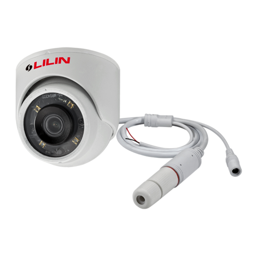
Part Description & Dimensions

- Bottom Chassis
- Lens
- Light sensor
- Microphone
- Power jack (DC12V ±10%)
- Reset Wire (strip off the wire insulation if needed; after the camera is reset, cut off the bare wire)
- RJ-45 Ethernet connector (supports PoE)
Installation
- First, take out the camera, loosen the set screw with a hex key. Then align the notches of the bottom chassis and the camera main body, and remove the bottom chassis (FIG.1 & 2).

- Insert the included screws (M4.0x25) through the holes marked as "a", and fix the camera in the desired location (FIG.3 & 4).

![warning]() Note: For outdoor installation, it is recommended to install a waterproof junction box.
Note: For outdoor installation, it is recommended to install a waterproof junction box.
- Attach the power cable and video cable to the video output jack and DC power input jack, respectively (FIG.5).

- Connect the RJ-45 Ethernet cable with a waterproof connector
First, remove the waterproof connector and unscrew the waterproof nut. Insert the Ethernet cable and connect to the RJ-45 connector with proper tools (FIG.6).

Then, tighten the waterproof connector and nut before the RJ-45 connector is connected to the camera (FIG.7).

- Connect the RJ-45 Ethernet cable with a waterproof connector
- Align the notches of the camera main body and the bottom chassis, press in and rotate to desired monitoring direction (FIG. 8).

Then adjust the pan, tilt, and azimuth of the camera to the desired viewing angle (FIG. 9)

- Make sure the light sensor is directly below the camera.
- Tighten the set screw with a hex key (FIG.10).


System Architectures
For connecting IP Camera series to the network, please follow one of the system architectures:
- Use DC12V power adaptor and network switch connected to a network.

- Use with PoE of the network switch connected to the network.

- Use PoE power injector and the network switch connected to the network.


Before Accessing IP Cameras
Before accessing the IP camera, make sure that the camera's RJ-45 network, audio, and power cables are properly connected. To set the IP address, consult your network administrator for an available IP address. The default IP address for each IP camera is 192.168.0.200. Users can use the default IP address for verifying the camera's network connection.
Emergency Factory Default
To restore the hardware to factory default settings, please follow these steps:
- Short the "RESET wire" for 10 seconds before releasing.
- The camera will be restored to factory default settings after approximately 90 seconds and will reboot automatically.
- Search for the IP device using the IPScan software.
- Start the IP device via an Internet browser.
- Enter the username and password to operate.
 NOTE 1: The factory default username and password are empty, and the user can set an account for login.
NOTE 2: The IP address will revert to the default setting of 192.168.0.200.
Software Requirements
Universal ActiveX software components are required for web interface display of JPEG or Full HD video. When you login to the IP camera by Internet Explorer, the security warning dialog box will prompt the installation of the Universal ActiveX. Click Install to download it.
Configuring IP Addresses via Web Interface
To change an IP address via web interface, type the default IP address (192.168.0.200) in the Internet browser and follow the steps below:
- Login to the Full HD IP camera with the set username and password.
- Click Basic Mode configuration hyperlink.
- Click Network->General hyperlink.
- Change the IP address, subnet mask, gateway, or HTTP port for the IP camera.
- Click Submit to verify the settings.
Configuring IP Addresses with IPScan Software
To change the settings of the IP address, subnet mask, gateway, or HTTP port, you can follow the steps below:
- Run the IPScan software.
- Click Refresh. All available devices should be listed in the device list.
- Select your device from the list provided.
- Change the IP address, subnet mask, gateway, or HTTP port for the IP camera.
- Click Apply to submit the settings.
- Click Refresh to verify the settings.


Login
The factory default username and password are empty. To login to the Full HD IP camera, please set the username and password on the login page.
Press [Login] to complete the setting and login simultaneously.

Password have to meet the following criteria:
- More than or equal to 8 characters.
- Allow uppercase letter, lowercase letter, number digit, and special character.
- Must have at least three types of character sets.

Documents / ResourcesDownload manual
Here you can download full pdf version of manual, it may contain additional safety instructions, warranty information, FCC rules, etc.
Download Lilin D/N HD IR IP CAMERA - IP Camera Installation Manual
Advertisement


Need help?
Do you have a question about the D/N HD IR IP CAMERA and is the answer not in the manual?
Questions and answers