Table of Contents
Advertisement
Quick Links
Advertisement
Table of Contents

Related Manuals for UNIS UP&AWAY


Summary of Contents for UNIS UP&AWAY
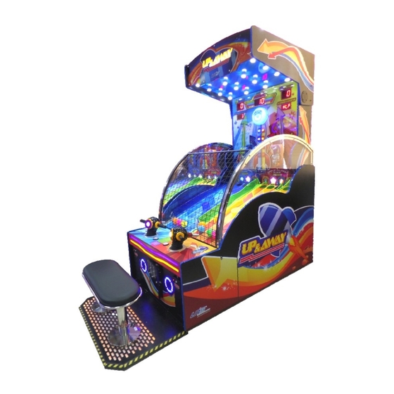
- Page 1 Operation Manual www.universal-space.com...
-
Page 2: Table Of Contents
CONTENT IMPORTANT SAFETY INSTRUCTIONS ............... 2 1. SPECIFICATIONS ................... 4 2. PACKAGE CONTENTS ................... 5 3. PART NAME ....................6 4. SET UP & INSTALLATION ................7 5. HOW TO PLAY ..................... 13 6. GAME OPTIONS ..................14 7. MAINTENANCE, INSPECTION ..............17 8. -
Page 3: Important Safety Instructions
Thank you for purchasing UP&AWAY from Universal Space. We hope you enjoy the product. This manual contains valuable information about how to operate and maintain your game machine properly and safely. It is intended for the owner and/or personnel in charge of product operation. - Page 4 This product is an indoor game machine. Do not install outdoors. Avoid installing in the following places to prevent fire, electric shock, injury and/or machine malfunctioning: Places subject to rain/moisture, or places subject to high humidity. Places subject to direct sunlight, or places subject to extremely hot or cold temperatures to ensure that it is used within the specified operating range.
-
Page 5: Specifications
1. SPECIFICATIONS Rated power supply: AC110V /60Hz Min. Power consumption: 70W Max. Power consumption:450W Dimensions: W1100× D2505× H2546.5 (mm) Weight: Approximately 300kg NOTICE: After turning off the game, please wait at least 1 minute before restarting again. Note: The contents of this manual may be updated without notice. -
Page 6: Package Contents
2. PACKAGE CONTENTS Open the package and make sure all the items are included: 1 x Body Assembly Following accessories Part No. Code Name Spec. Picture 23301000001 Power code 10A/250V-1.8M Φ5×20mm 21901000013 Fuse T10A 250VAC 41000000114 Ball VBS75 41411301001 Manual 25300171002... -
Page 7: Part Name
3. PART NAME... -
Page 8: Set Up & Installation
4. SET UP & INSTALLATION This product is an indoor game machine. Do not install outdoors. Refer to IMPORTANT SAFETY INSTRUCTIONS (Pg. 2) for places to avoid Place the unit on a dry level surface Ventilation openings in the back of the unit must not be obstructed by objects or by wall. 4.1 Play Zone This machine requires space for playing and for maintenance as shown below. - Page 9 4.2 Level Adjustment Install this machine on a flat surface. Adjust levers to lift casters off the ground to level the game. If the game is installed on an unsuitable floor, it could cause game malfunction. To secure the game, adjust the Leveler down until it touches the floor, lifting the casters off the ground by 5mm.
- Page 10 4.4 Connecting Power WARNING: Check the voltage rating before you connect the equipment to an electrical outlet to ensure that the required voltage and frequency match the available power source. Please refer the label of the machine. Do not plug the equipment power cables into an electrical outlet if the power cable is damaged.
- Page 11 4.4 How To Install Marquee Assy. Step 1: Remove 1 screw from both sides on top of the cabinet. Step 2: Lift up the marquee in the correct position by 2 people. One needs to support the marquee in the front. The other needs to install 4 provided screws (M6*40) from the accessory box to fix the marquee.
- Page 12 Step 3: Take the connection metal plate from accessory box. Fix it to the cabinet with 8 screws (M6*20) as the picture shown. Step 4: Find the cable connector at the back of the cabinet. Then connect it to the other end from the top marquee hole.
- Page 13 4.5 How To Install Seat Assy. Step 1: Push the seat assembly at the front of the cabinet. Make seat assembly mounting holes and cabinet mounting holes horizontal alignment. Step 2: Take out seat light cable connector, and get it though the hole on the bottom of the cabinet.
-
Page 14: How To Play
5. HOW TO PLAY... -
Page 15: Game Options
6. GAME OPTIONS Check the attached I/O chart and schematic diagram, PC plan available machine input and output correspond to each connection position. Based on the DIP adjustment can be set the machine control signal. DIP regulating reference I/O list, capital letters for factory Settings, user can adjust themselves according to the operation condition. - Page 16 Display: 1P TIME LED<1>1-2 BONUS LED<1>3-5 2P TIME LED<1>7-8 1P TICKET LED<2>1-3 2P TICKET LED<2>4-6 Error display: If the input signal is not normal when you turn on the machine, The score LED displays SW numbers with wrong. Clear memory: Hold on TEST button and press Reset button, then unclinch Reset button.
- Page 17 How To Adjustment Blowing Rate: Step 1: Open control panel, there are 2 metals on the windpipe, you can use these 2 metals to adjust air volume. Step 2: You can loosen windpipe metal to adjust degree. 1 degree is maximum air volume.
-
Page 18: Maintenance, Inspection
7. MAINTENANCE, INSPECTION 8.1 Safety Check Check the points listed before operating the machine. These checks are necessary for safe machine operation: 1. Try to run the game before operation each day. 2. Conduct monthly routine checks of game components ensure good working condition 3. -
Page 19: Overall Construction
8. OVERALL CONSTRUCTION 8.1 Mechanical Part 8.1.1 Side door assy. Part No. Code Name U103-101-000 20211301002 L bend U103-601-000 20611301002 L side plexi. U103-102-000 20211301005 Safety net U103-601-000 20611301002 R side plexi. U103-103-000 20211301003 R bend... - Page 20 8.1.2 Control panel, front door assy.
- Page 21 Part No. Code Name U103-104-000 26000005000 Wiring box support base U103-105-000 20611301022 Protection cover A U103-106-000 29911301013 Speaker assembly U103-108-000 26000008000 2.5” leveller U103-501-000 20311301037 Blower base board U103-401-000 23401001003 Blower(BR-211B) U103-112-000 20211301081 Gas connector U103-113-000 20211301080 Gas pipe hole platen U103-601-000 20211301079 Gas puipe...
- Page 22 8.1.3 Fairway assy.
- Page 23 Part No. Code Name U103-606-000 20211301017 Retainer ring U103-123-000 20211301029 Marquee fixed plate D U103-607-000 20511301004 Star light board decal U103-608-000 20611301004 L-side track piece B U103-609-000 20611301005 L-side track piece C U103-610-000 20611301009 L-side track piece G U103-611-000 20611301008 L-side track piece F U103-612-000 20611301012...
- Page 24 8.1.4 Main panel assy. Part No. Code Name U103-125-000 20211301020 Bearing bracket U103-404-000 20106000136 Deep groove ball bearing U103-624-000 GTSP-HM-01 Main panel decal U103-126-000 26000041000 3mm screw washer Digital display board U103-127-000 20211301021 bracket U103-625-000 20511301003 Digital display decal U103-626-000 20511301005 Alarm bell decal U103-128-000...
- Page 25 8.1.5 Marquee assy. Part No. Code Name U103-129-000 20211301028 Spotlight bracket U103-130-000 20211301029 Marquee fixed plate D U103-131-000 20211301024 Marquee rotation axis U103-627-000 20511301002 Marquee decal 8.1.6 Marquee assy. Part No. Code Name U103-405-000 23404000047 DC motor U103-132-000 20211301031 PC fixed block U103-502-000 20311301035 Gate mechanism action board U103-406-000 25105000006 Guide rail...
- Page 26 8.1.7 Gun assy. Part No. Code Name U103-628-000 20611301027 Gun shell U103-138-000 20211301049 Gun handle U103-139-000 20211301048 Gun light shade bracket U103-629-000 20611301028 Gun light shade A U103-630-000 20611301025 Gun light shade B U103-140-000 20211301038 Gun R fixed board U103-141-000 20211301040 Up&...
- Page 27 8.1.8 Seat assy. Part No. Code Name U103-634-000 20611301032 Seat surface U103-148-000 20211301078 Stainless steel ring U103-149-000 20211301077 Seat standard U103-150-000 20211301074 Seat cover fixed metal U103-635-000 20611301033 Shockproof sheet A U103-636-000 20611301034 Shockproof sheet B U103-637-000 20611301031 Light barrier U103-151-000 20211301067 Light bar fixed board...
- Page 28 8.1.9 Rabbit assy. Part No. Code Name U103-638-000 20511301007 Rabbit vacuum foam U103-157-000 20211301059 Connection plate U103-503-000 20311301039 Rabbit fixed board U103-158-000 20211301062 Tortoise& rabbit fixed plate U103-159-000 20211301061 Tortoise& rabbit connection plate U103-504-000 20311301036 Rising mechanism fixed plate U103-160-000 20211301056 Sensor fixed metal U103-161-000...
- Page 29 8.1.10 Tortoise assy. Part No. Code Name U103-640-000 20511301006 Tortoise vacuum foam U103-157-000 20211301059 Connection plate U103-505-000 20311301038 Tortoise fixed board U103-158-000 20211301062 Tortoise& rabbit fixed plate U103-159-000 20211301061 Tortoise& rabbit connection plate U103-504-000 20311301036 Rising mechanism fixed plate U103-160-000 20211301056 Sensor fixed metal U103-161-000...
- Page 30 8.2 Electrical Part Part No. Code Name U103-401-000 21701000014 IO board U103-402-000 21713000011 Motor control PCB U103-433-000 21714000153 Blower PCB U103-405-000 21709000001 Relay PCB U103-403-000 21602000094 Power supply U103-404-000 21602000010 Power supply...
- Page 32 Part No. Code Name U103-428-000 22003080001 Marquee light U103-427-000 22004070001 Marquee spotlight U103-408-000 21706000037 Bonus digital board U103-407-000 21706000047 Time digital board U103-406-000 21706000032 Score/ticket digital board U103-431-000 29711301001 Fire protection bell light PCB U103-436-000 22008000036 Tortoise indicator light U103-437-000 22008000040 Rabbit indicator light U103-409-000 20740930001 Star light PCB...
- Page 33 Part No. Code Name U103-413-000 21412000001 Terminal U103-415-000 21901000013 Fuse U103-412-000 22601000005 Small rocket SW U103-414-000 23201000001 Filter U103-438-000 23301000001 Power cord Part No. Code Name U103-421-000 23000000005 Meter U103-416-000 22403000001 POT knob U103-418-000 22501000017 U103-419-000 22402030001 Reset button(green) U103-420-000 22402010001 Service button(red) U103-417-000 21709000002 POT connection board...
-
Page 34: Decal
9. Decal Part No. Code Name U103-701-000 20511301001 Main panel decal U103-702-000 20511301002 Marquee decal U103-703-000 20511301010 Control panel decal Control panel light PCB U103-704-000 20511301011 decal U103-705-000 20511301012 Front door decal U103-706-000 20511301013 Base L front decal U103-707-000 20511301014 Base L back decal U103-708-000 20511301015 Base R front decal... - Page 35 Part No. Code Name U103-715-000 20511301003 Bonus LED decal U103-716-000 20511301004 Star light PCB decal U103-717-000 20511301005 Alarm bell decal U103-718-000 20511301006 Tortoise vacuum foam U103-719-000 20511301007 Rabbit vacuum foam U103-720-000 20511301008 L fairway decal U103-721-000 20511301009 R fairway decal U103-722-000 20511301021 1P link button decal U103-723-000 20511301022...
- Page 36 Part No. Code Name U103-726-000 20511301026 Number label U103-727-000 20511301027 Non-certification 110V nameplate U103-728-000 20511301028 CE certification 110V nameplate U103-729-000 20511301029 FCC certification 110V nameplate U103-730-000 GTSP-HM-30 Instruction label U103-731-000 25600000001 Coin counter label U103-732-000 25600000002 Ticket counter label U103-733-000 25600000003 Volume label U103-734-000 25600000006 Reset label...
- Page 37 Part No. Code Name U103-744-000 20511301031 Wiring label...
-
Page 38: Io Chart
IO chart Item Content Coin per game Game time 120s 180s Demo music 240s Item Content Ticket of each hole Continue Ticket to play error Call attendant BONUS activate in single play... - Page 39 Item Content Fixed ticket Fixed ticket setting Mercy ticket Link payout mode* ticket BONUS memory Item Content Bonus + per coin Linkup Bonus+ per player (activate when more than 1 player playing) Linkup BONUS ticket Note: If one of the player win the Bonus, two ticket payout mode as below: ...
-
Page 40: Wiring Diagram
Wiring diagram GTSP-PX-01 GTSP-PX-05... - Page 41 GTSP-PX-01 GTSP-PX-05...
- Page 42 Have Questions? Contact us! www.universal-space.com International Support Center USA Support Center Tel: +1-905-477-2823 Tel: 972-241-4263 Fax: +1-905-477-2660 Fax: 214-919-4918 Email: service@universal-space.com Email:tsnelling@unisusasupportcenter.com (Contact: Clement Yau) (Contact: Tim Snelling)
Need help?
Do you have a question about the UP&AWAY and is the answer not in the manual?
Questions and answers