Table of Contents
Advertisement
Advertisement
Table of Contents

Related Manuals for UNIS EXTREME SHOT


Summary of Contents for UNIS EXTREME SHOT
- Page 1 Operation Manual www.universal-space.com...
- Page 3 Have Questions? Contact us! International Support Center USA Support Center Tel: +1-905-477-2823 Tel: 972-241-4263 Fax: +1-905-477-2660 Fax: 214-919-4918 Email: service@universal-space.com Email: service@unisusasupportcenter.com...
-
Page 4: Table Of Contents
Extreme Shot Manual CONTENT IMPORTANT SAFETY INSTRUCTIONS ............. 2 1. SPECIFICATIONS ................... 4 2. PACKAGE CONTENTS ................6 3. PART NAME ..................10 4. SET UP & INSTALLATION ..............11 5. HOW TO PLAY ..................24 7. ERROR MESSAGE AND RECOVERY ..........29 8. -
Page 5: Important Safety Instructions
Extreme Shot Manual Thank you for purchasing Extreme Shot. We hope you enjoy the product. This manual contains valuable information about how to operate and maintain your game machine properly and safely. It is intended for the owner and/or personnel in charge of product operation. - Page 6 Extreme Shot Manual Use the following safety guidelines to help ensure your own personal safety and to help protect your equipment and surrounding environment from potential damage. This product is an indoor game machine. Do not install outdoors. Avoid installing in the following places to prevent fire, electric shock, injury and/or machine malfunctioning: ...
-
Page 7: Specifications
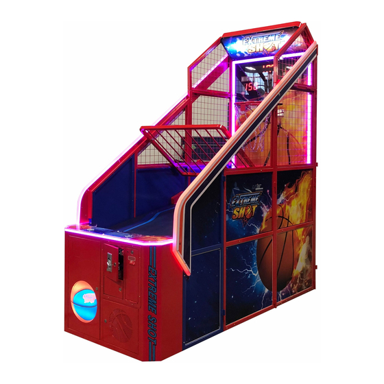
Extreme Shot Manual 1. SPECIFICATIONS Rated power supply: AC110V 50/60Hz; AC220V 50/60Hz Min. Power consumption: 90W Max. Power consumption: 200W Dimension: W40.68×D98.82×H111.73 in Dimensions Container: W Weight:Approximately 573.2 lb Part No: E103 Model No: A-399 NOTICE: After turning off the game, please wait at least 1 minute... - Page 8 Extreme Shot Manual 111.73 in 98.82 in Note: Game parameters are subject to change without notice.
-
Page 9: Package Contents
Extreme Shot Manual 2. PACKAGE CONTENTS Open the package and make sure all the items are included: 1. 1 x Body Assembly Name Picture Name Picture Control Main body panel assy. Ball Marquee gate assy. assy. Playfield Beam Front Playfiel... - Page 10 Extreme Shot Manual 2. Following accessories Part No Code No. Description Spec. picture 1 E103-185-000 20113000051 C flat washer 8×1.6h 2 E103-186-000 20113000053 C flat washer 6×1.6h C large 3 E103-187-000 20113000035 Φ6xΦ30x3h washer Non-metallic 4 E103-188-000 20102040023 hexagon lock...
- Page 11 Extreme Shot Manual Part No Code No. Description Spec. picture Hexagon flat 9 E103-193-000 20101048010 round head M8×25 screws Cross recessed pan 10 E103-194-000 20101020145 M8×20 head screw suite Hexagon flat 11 E103-195-000 20101008003 round head M6×60 screws Hexagon flat...
- Page 12 Extreme Shot Manual Part No Code No. Description Spec. picture 19 E103-443-000 25300171002 171A 20 E103-444-000 25300172002 171B Photoelectric 21 E103-445-000 21504000001 50×55 SW reflector Φ5×20mm 22 E103-446-000 21901000012 Fuse T5A 250VAC 23 E103-447-000 41000000015 Basketball 24 E103-448-000 41440000177 Manual...
-
Page 13: Part Name
Extreme Shot Manual 3. PART NAME Marquee Assy. Display Gate Assy. Control panel Coin Assy. (card system wiring inside ) Ticket dispenser Assy. -
Page 14: Set Up & Installation
Extreme Shot Manual 4. SET UP & INSTALLATION This product is an indoor game machine. Do not install outdoors. Refer to IMPORTANT SAFETY INSTRUCTIONS (Pg. 3) for places to avoid Place the unit on a dry level surface ... - Page 15 Extreme Shot Manual 4.3 Play Zone This machine requires space for playing and for maintenance as shown below. Leave space around the game upon installation: Service area: 31.5 in Play area: 20 in 30cm Service 操作区 area 本 机 摆 放...
- Page 16 Extreme Shot Manual 4.4How to Install the Machine 4.4.1 Remove the packing (This is the picture without packing.)
- Page 17 Extreme Shot Manual 4.4.2 Front bracket Open the Front bracket (L&R)
- Page 18 Extreme Shot Manual 4.4.3 Install the cross beam and bracket Attach the bracket (top) with 6 hexagon flat round head screws 1 4103-198-000) (○ Turn up the bracket (top) and attach it. Attach the bracket (top) with hexagon flat round head screws (...
- Page 19 Extreme Shot Manual 4.4.4 Install front bracket plate and cross beams Install front bracket plate. Attach the cross beams with hexagon flat round head screws ( ○ 103-196-000). Attach the brackets with hexagon flat round head screws ( ○ 8 E103-192-000 )...
- Page 20 Extreme Shot Manual 4.4.5 Install ball track plate Attach the marquee assy. with cross recessed hexagon head bolt suite (○ 1 5E103-199-000) Attach the front playfield and ball gate assy. with hexagon flat round head screws non-metallic hexagon lock nut(○ 9 E103-193-000)...
- Page 21 Extreme Shot Manual 4.4.6 Install ball front bracket plate Attach the ball front bracket with hexagon flat round head screw and non-metallic hexagon lock nut(○ 7 E103-191-000) (○ 4 E103-188-000) . Attach the control panel assy. with cross recessed hexagon head bolt suite (103-194-000○...
- Page 22 Extreme Shot Manual 4.4.7Install side ligh Install the side light box with hexagon flat round head screws 103-197-000)and cross ○ recessed countersunk head screw (○ 2 5E103-200-000)
- Page 23 Extreme Shot Manual 4.4.8 Install ball front bracket plate Attach the side light box with hexagon flat round head screws ○ 103-195-000) nut( ○ 6 E103-190-000). flat washer( ○ 2 E103-186-000) Attach the bottom of sides marquee with hexagon flat round head screws ( ○...
- Page 24 Extreme Shot Manual 4.5 Connecting Power WARNING: Check the voltage rating before you connect the equipment to an electrical outlet to ensure that the required voltage and frequency match the available power source. Please refer the label of the machine.
- Page 25 Extreme Shot Manual 4.6 Wiring Instruction Step 1:Connect the connecters individually according to the labels. Step 2: For reference, this picture is showing the wiring layout of the bottom of the cabinet. (Attach and tighten with nylon cable ties. Part # E103-500-000 ) 4.7 Disassembly...
- Page 26 Extreme Shot Manual 4.7.1 Remove the connecter on the main board. 4.7.2 Remove the connecters and the power cord. 4.7.3 Loosen the screws on both sides of the control panel.
-
Page 27: How To Play
Extreme Shot Manual 4.7.4 Remove the control panel as shown. 5. HOW TO PLAY 5.1 Insert coins and press button to begin. 5.2 Score instruction Stage 1: Reach 30 points to enter into Stage 2 For single player Stage 2: Reach 60 points to enter into Stage 3... - Page 28 Extreme Shot Manual 6. GAME OPTION 6.1 Testing 6.1.1 Main board test RESET TEST Button Button Main board Test: Press TEST button once on the main board, it displays 8.7.6.5.4.3.2.1. and 87654321 to test LED correct or not; Press TEST button once again, it displays1, 1#, 1,2 DIP sw state;...
- Page 29 Extreme Shot Manual 6.1.2 Signal test Sensor board To test whether the HOOP is in the center. If the light is on it indicates that the HOOP is in the center position. If the light is off or shimmering, the HOOP is not in the correct position.
- Page 30 Extreme Shot Manual 6.2 Adjustment button instruction Coin meter Ticket meter Volume Reset the ticket dispenser Open the coin door there is a meter panel. Press service button to get into the setting menu. 6.2 Setting menu 6.2.1 DIP SW1...
- Page 31 Extreme Shot Manual 6.2.5 DIP SW2 Item Content Stage per game 6.2.6 DIP SW2 Item Content Game time(s) Item Game time (s) Content Stg.1 Stg.2 Stg.3 Stg.4 Stg.5 6.2.7 DIP SW2 Item Content High Score Initial Value 6.2.8 DIP SW2...
-
Page 32: Error Message And Recovery
Extreme Shot Manual Item Pass stage score Content Stage 1 Stage 2 Stage 3 Stage 4 Stage 5 6.2.10 DIP SW3 Item Content 3-point time (s) Item 3-point time (s) Content Stage 1 Stage 2 Stage 3 Stage 4 Stage 5 Error display:... - Page 33 Turn on power SW again. If appeared Circuit protector make power SW again and again, machine has Power cutting in cutting state anomaly. Please contact with UNIS Service. Coin mech. fault or sample coin Change coin mech. or sample coin. not installed.
-
Page 34: Maintenance & Inspection
Extreme Shot Manual 8. MAINTENANCE & INSPECTION 8.1 Safety Check Check the points listed before operating the machine. These checks are necessary for safe machine operation: 1. Test game before operation each day. 2. Conduct monthly routine checks of game components ensure good working condition 3. -
Page 35: Overall Construction
Extreme Shot Manual 9. OVERALL CONSTRUCTION 9.1 Frame Part No. Code Name Material E103-101-000 20211603D012 R side front support bracket Q235 E103-102-000 20211603D044A R side front panel Q235 E103-501-000 20311603D001 Front protection board E103-103-000 20211603D094 R side middle support bracket... - Page 36 Extreme Shot Manual Part No. Code Name Material 13 E103-504-000 20311603D011 Front fairway board Plywood Back middle cross beam support 14 E103-110-000 20211603D034 Q235 bracket Front middle cross beam support 15 E103-111-000 20211603D033 Q235 bracket 16 E103-112-000 20211603D007 Cross beam...
- Page 37 Extreme Shot Manual Part No. Code Name Material 1 E103-122-000 20211603D079 Front support bracket fixed sleeve Q235 2 E103-123-000 20211603D092 Tripping ball front support bracket Square tube 9.3 Moving mechanism Part No. Code No. Name Material E103-125-000 20211603D072 Hoop Q235...
- Page 38 Extreme Shot Manual Part No. Code No. Name Material E103-138-000 20211603D036 Rear motor cover Q235 E103-401-000 51001060001 Capacitor YN70-15Z/70JB100 E103-402-000 23405000022 Motor G1032-27110v E103-139-000 21504000001 Photoelectric SW reflector Mirror steel E103-404-000 21501000041 Reflect-sensor XUB1ANANL2 9.4 Ball gate mechanism Part No.
- Page 39 Extreme Shot Manual 9.5 Side light Assy. Part No. Code No. Name Material E103-148-000 20211603D017 L side light box front cover Q235 E103-149-000 20211603D024 R side light box front cover Q235 E103-507-000 20311603D003 L side light box board Q235 E103-508-000 20311603D004...
- Page 40 Extreme Shot Manual 9.6 Main panel light Part No. Code No. Name Material E103-602-000 20611603D006 Main panel L lamp ring White plexi. E103-161-000 20211603D056 Panel light converted Q235 9.7 Control panel Assy.
- Page 41 Extreme Shot Manual Part No. Code No. Name Material Control panel R bottom E103-162-000 20211603D030 Q235 door E103-163-000 20211603D099 Speaker net Net board E103-164-000 20311603D006 Bass speaker E103-165-000 20211603D035 Coin door Q235 E103-166-000 22601000005 Rocket SW(S) T125/55 E103-408-000 22801000055 Ellipse speaker...
- Page 42 Extreme Shot Manual 9.8 Back upper bracket Assy. Part No. Code No. Name Material E103-172-000 20211603D037 Dot matrix cover Q235 E103-173-000 20211603D073 Back top support bracket Q235 E103-174-000 20211603D069 Hinge R Q235 E103-175-000 20211603D068 Hinge L Q235 E103-512-000 20311603D010 Main panel top...
- Page 43 Extreme Shot Manual 9.9 Light box Assy Part No. Code No. Name Material White PVC E103-606-000 20611603D004 foam Light box backboard board E103-607-000 20511603D004 Light box light panel Clear plexi E103-608-000 20511603D003 Light box decal Clear plexi E103-177-000 20211603D027 Light box...
- Page 44 Extreme Shot Manual 9.10 Light box Assy(Option accessiories) Part No. Code No. Name Material E103-172-000 20211603D105 Q235 Light box front rail E103-173-000 20511603D026 Light box decal Clear plexi E103-174-000 20511603D027 Clear plexi Light box light panel White PVC E103-175-000 20611603D008...
- Page 45 Extreme Shot Manual 9.10 Decal part...
- Page 46 Extreme Shot Manual Part No. Code No. Name Material 1 E103-701-000 20511603D010 Rear ball track δ0.3PVC Scrub 2 E103-702-000 20511603D009 Mid ball track δ0.3PVC Scrub 3 E103-703-000 20511603D008 Front ball track δ0.3PVC Scrub 4 E103-704-000 20511603D011 δ0.3PVC Scrub L side (Top) decal...
- Page 47 Extreme Shot Manual Part No. Code No. Name Material E103-721-000 25600000101 meter label PVC100u E103-722-000 25600000036 High voltage warning (small) PVC100u E103-723-000 25600000074 Fuse T5A/250V PVC100u E103-724-000 25600000071 New voltage 110V PVC100u E103-725-000 25600000016 Power SW label A PVC100u E103-726-000 25600000091...
- Page 48 Extreme Shot Manual 9.11 Electrical part Coin counter Ticket counter Volume Reset Test Setting...
- Page 49 Extreme Shot Manual Part No. Code No. Name Material E103-414-000 29709030001 V9 board V9 1.4 E103-415-000 21714000228 Dot matrix board 76*304mm E103-449-000 20211603D104 Relay pedestal electrolytic plate E103-436-000 Relay 22140000002 SSR-25DA E103-417-000 21602000001 Power supply BTX-3039(110V220V) E103-412-000 22801000047 Round speaker 4“8Ω15W...
- Page 50 Extreme Shot Manual Part No. Code No. Name Material E103-438-000 22002013002 Sides light DC12V 5050LED 11.7 W5630-LC85cm-60z/m-D E103-442-000 22003080008 Marquee light C12V...
-
Page 51: Wiring Diagram
Extreme Shot Manual 10. WIRING DIAGRAM 10 P 45 P 60 P...
Need help?
Do you have a question about the EXTREME SHOT and is the answer not in the manual?
Questions and answers