Advertisement
Quick Links
Advertisement

Related Manuals for Pilot Communications Predator Sport Jet 126”


Summary of Contents for Pilot Communications Predator Sport Jet 126”
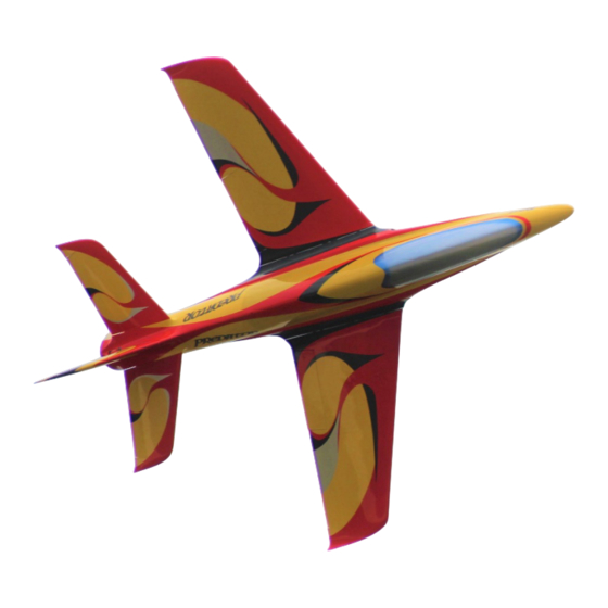
- Page 1 Predator Sport Jet 126” USER MANUAL...
- Page 2 ● Thank you for purchasing our Predator Sport Jet plane. we strive to achieve a good quality quick build ARF aircraft . It requires the least amount of assembly of any ARF kit to obtain the maximum performance. ● Both the design and manufacturing have been undertaken to the highest standards, using best quality hardware, covering, wood &...
- Page 3 Install kit contents: (Some contents like fuel tank etc… has already installed in fuselage) Aluminum tube Accessories pack:...
- Page 4 Accessories pack includes: Socket head cap screws Counterstunk cross screws Cross round head with medium screws Tapping screws Hexagon screw in metric system(SHCS) Battery bandage Servo aluminum angle Metric Allen Wrench Push rot wrench Wring clamp Crowbar Crowbar Push rot Oil nipple suit Extension cord (Include 4 in 1 and 3 in 1 extension cord) (Some of accessories like screw/cord ect…...
- Page 5 Landing gear module(optional): Landing gear Pilot landing gear controller Servo module(optional): Servo module(optional): Servo: PY20AH Servo arm: Pilot Futaba aluminum alloy 1.2”...
- Page 7 1: Install the servo to the nose landing gear. Install the servo arm and the push rod. Adjust it to make sure the plane can go straight approx. You still can adjust by radio after install it.
- Page 8 3: Place the nose gear to the mounting and adjust it to the correct position, then mark the 4 mounting screws hole. 4: Before you drilling the mounting screws hole , please make sure there is nothing to get stuck when it open and close.
- Page 9 6: Carefully arrange the nose 5: This is how it looks like after gear retract wire lead and the installation. steering wire as well ... 8: You can use the gear control 7: Install the nose retract gear to box to operate the landing gear the fuselage.
- Page 11 4.Remove the gear and carefully drill 3.Double check the positioning of the holes to accept your chosen your gear before drilling any holes. screws. We recommend the use of Make sure that the gear movement bolts and blind nuts, however wood is free of any obstacles.
- Page 12 1.Screw the servo to the included The control horns are pre-installed at the aluminium L shaped brackets, then factory, ready for use. install the servo arm on to the servo, making sure that this is centred 2.Place the servo over the servo plate 3.Drill out the four holes in the plate, then 3.Drill out the four holes in the plate, then making sure that the arm moves freely...
- Page 13 4.Attach the included pushrods and ball links between the servo arm and the control horn. 5.Route the servo wire through the inside of the wing toward the fuselage, before securely screwing the servo plate to the wing with four wood screws...
- Page 14 Aileron servo / Flaps servo / Gear installed 7.Just one connector for aileron/flaps/landing gear/brakes. 6.Use a thin ply as a back plate and One side of the connector can be installed the 4 in 1 connector , use 5 screwed to the fuselage, while the min epoxy to glue it from inside of the other is left inside the wing, loose, fuselage.
- Page 15 1.Insert the servo into the rudder, in its allocated slot, with the servo shaft closest to the rudder.
- Page 16 2.Screw the servo in place, and then install the servo arm on to the servo, making sure that this is centraed. Attach the included pushrods and ball links between the servo arm and the control horn. The rudder extension wire connector.
- Page 17 Elevator servo assembly 1.Take out the elevator plating from the wing and use the supply L-shape aluminium braket to install the servo...
- Page 18 3.Rudder servo and servo arm installed...
- Page 21 The 126” Predator’s fuselage divided three pieces. Rear section easily removable for transport Fuselage divided three parts: Front part (For front landing gear, electronic device) Middle part(For tank, engine, wings) Behind part(For exhaust pipe, rudder, elevator)...
- Page 22 Front – Middle part 1.First, put the front fuselage and middle fuselage on table or support shelf. And make sure front-middle part can connect through the limit hole. 2.When connected, use the head screws to fasten all of it. and make sure all of screws are tight.
- Page 23 Middle - Behind part 1.When you finish the front-middle part. Then connect the middle-behind part like before.
- Page 24 Because the Predator fuselage divide three part. and each part have many electric parts need assemble, so there is many circuit…… So for easy arrange the circuit, these pictures showed how the circuit arrange in the fuselage. For circuit arrange easily, we set the circuit arrangement tube in each fuselage, it’s under the mounting plate or at fuselage’s left/right side.
- Page 25 The front part circuit arrangement(electric parts ect……)
- Page 26 The middle part circuit arrangement(wings, gear)
- Page 27 The behind part 3 in 1 connector circuit arrangement (rudder, elevator) All these pictures are suggestion, you can arrange circuit by your way. And for easy arrange these circuit, you may need some tools like tweezers, stay wire ect…...
- Page 28 The electric parts arrange, we divided it for two parts: front part is oil filler(smoke oil filler)hole MERCURY display, switch. behind part is MERCURY, landing gear controller, oil pump, pump, receiver, flying control system. ect……...
- Page 29 For install the engine, we suggest install the exhaust nozzle first, when the nozzle setting done, we can locate the engine’s setting position, and install it.
- Page 30 When arrange the engine, must make sure the screws are tight with engine and mounting plate...
- Page 31 The 126” predator use PilotRC 3 in 1 Kevlar tank. It’s included 7800ml fuel tank, 2400ml smoke tank and 500ml UAT...
- Page 36 Aileron: 36mm Rudder: 432mm Elevator: 33 mm Flaps: 55mm for take off 120mm for landing CG:The CG is 430mm from the front leading edge on the root of the wing.
- Page 37 ■ Make sure you have the right model programmed into your transmitter ■ Check the direction of each surface not and also right before you take off . ■ Remember nothing wrong on the ground ever improves in the air ■...
Need help?
Do you have a question about the Predator Sport Jet 126” and is the answer not in the manual?
Questions and answers