Table of Contents
Advertisement
Available languages
Available languages
Quick Links
SISTEMAS VRV
UNIDADES INTERIORES
2ª GENERACIÓN
VRV SYSTEMS
2nd GENERATION INDOOR UNITS
GAMA CST4C
Cassette 4 vías
MANUAL DE
INSTRUCCIONES
INSTRUCTION MANUAL
Escanee para ver este manual en otros idiomas y actualizaciones
Scan for manual in other languages and further updates
Manuel dans d'autres langues et mis à jour
Manual em outras línguas e actualizações
V.2
Advertisement
Chapters
Table of Contents

Subscribe to Our Youtube Channel
Related Manuals for EAS Electric GAMA CST4C


Summary of Contents for EAS Electric GAMA CST4C
- Page 1 SISTEMAS VRV UNIDADES INTERIORES 2ª GENERACIÓN VRV SYSTEMS 2nd GENERATION INDOOR UNITS GAMA CST4C Cassette 4 vías MANUAL DE INSTRUCCIONES INSTRUCTION MANUAL Escanee para ver este manual en otros idiomas y actualizaciones Scan for manual in other languages and further updates Manuel dans d'autres langues et mis à...
-
Page 2: Table Of Contents
Contenidos Manual de instrucciones ..............1 • Asegúrese de que se utilice un circuito independiente para la fuent Accesorios ....................2 de alimentación. Todas las partes eléctricas deben cumplir con las leyes y regulaciones locales, y lo que se indica en este manual de 1. - Page 3 Precaución • Instale la tubería de descarga de agua de acuerdo con los pasos descritos en este manual, y asegúrese de que la descarga de agua sea suave y que la tubería esté correctamente aislada para evitar la condensación. La instalación incorrecta de la tubería de descarga de agua puede provocar fugas de agua y dañar los muebles de interior.
-
Page 4: Accesorios
Accesorios Verifique que el aire acondicionado incluya los siguientes accesorios. Apariencia Cantidad Código Descripción Manual de instalación Tuerca Arandela Plantilla de instalación M6 Tornillo Aislante para tubería frigorífica Espuma (250x250x8) Espuma (60x100x5) Aislante para tubería Abrazadera Brida Conexión para desagüe Tuerca Protector Cable de conexión... -
Page 5: Antes De La Instalación
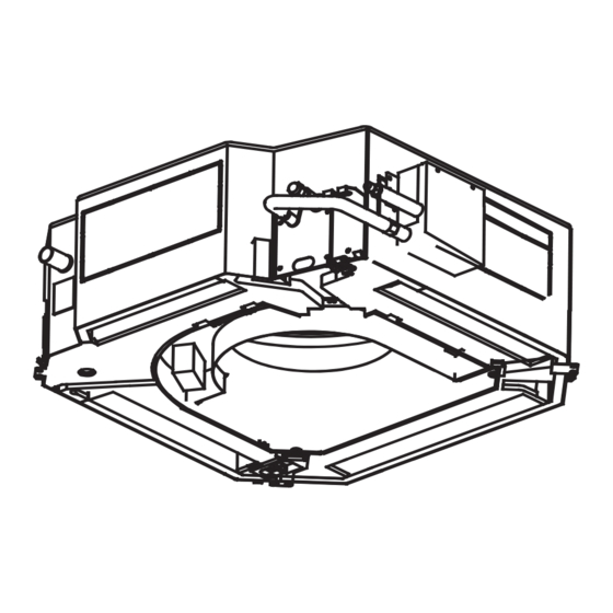
1. Antes de la instalación 1. Determine la ruta para mover la unidad al sitio de instalación. 2. Primero, abra y desempaquete la unidad. Luego, sostenga los asientos del colgador (4 unidades) para mover la unidad. Evite ejercer fuerza sobre otras partes de la unidad, especialmente la tubería de refrigerante, la tubería de descarga de agua y las piezas de plástico. - Page 6 Taladre agujeros cuadrados de 640 mm x 640 mm en el techo según la disposición del panel de instalación (accesorio 2). Vea la Figura 3.5. Vea la Figura 2.1 para acceso de mantenimiento. Estructura de losa de hormigón original. El centro de la abertura del techo debe coincidir con el centro del cuerpo de la unidad interior.
- Page 7 Ventilación de la tubería de refrigerante (lado del gas D) Unidad interior Tubería de ventilación de refrigerante (lado líquido C) ϕ32 (diámetro exterior de la tubería de descarga de agua) Tornillo M6x12 Panel de instalacion (accesorio) Figura 3.8 Precaución • Antes de instalar la unidad interior, asegúrese de quitar los amortiguadores utilizados para el transporte entre el ventilador y el zócalo de la tubería (consulte la Figura 3.9).
- Page 8 Gancho de la Gancho de Lado de la bandeja de drenaje panel tubería Lado de drenaje 45° Figura 3.13 Motor Swing Tornillo de Precaución gancho • No coloque el panel de manera que quede hacia abajo o se apoye contra la pared. Tampoco lo coloques sobre un objeto Destornillador sobresaliente.
- Page 9 Conducto de distribución No se permite brecha Conducto de Conducto de distribución distribución Figura 3.18 Φ75 El lado con EXV no puede ser conectado con el conducto de distribución 1. Primero afloje la tuerca Conducto de distribución Aire fresco Figura 3.22 2.
-
Page 10: Instalación De Tuberías De Refrigerante
4. Instalación de tuberías de refrigerante Precaución 4.1 Requisitos de longitud y diferencia de nivel para las • Aplique el par de apriete adecuado de acuerdo con las condiciones de conexiones de tuberías a las unidades interiores y exteriores instalación. Un par de torsión excesivo dañará la tapa del zócalo, y la Los requisitos de longitud y diferencia de nivel para las tuberías de tapa no estará... -
Page 11: Instalación De Tuberías De Descarga De Agua
5. 5. Instalación de tuberías de descarga de agua 5.2 Prueba de descarga de agua 5.1.Instalación de tuberías de descarga de agua para unidad interior -Antes de la prueba, asegúrese de que la tubería de descarga de agua sea lisa y de que cada conexión esté... - Page 12 6.1 Conexión del cable de alimentación Consulte las Tablas 6.1 y 6.2 para las especificaciones del cable de alimentación y del cable de comunicación. Una capacidad de cableado Utilice una fuente de alimentación dedicada para la unidad interior que sea diferente de la fuente de alimentación para la unidad exterior.
- Page 13 (Conecte el extremo blindado del cable Unidad blindado a la hoja de metal de la caja exterior del controlador electrónico " " aquí). (P Q E) Línea de señalización entre unidades exteriores. Display Unidad interior 1 Conectando la capa blindada del alambre blindado Unidades interiores y exteriores Cable de comunicación.
-
Page 14: Configuración En El Sitio
7. Configuración en el sitio SW1_1 7.1 Ajustes de capacidad La compensación de temperatura del modo de enfriamiento es 0 ° C Instale el interruptor DIP de la placa PCB en la caja de control eléctrico interior para satisfacer diferentes usos. Una vez que se La compensación de temperatura del modo de enfriamiento hayan realizado los ajustes, asegúrese de apagar de nuevo el es 2 °... -
Page 15: Prueba De Funcionamiento
Una vez completada la instalación, conserve el manual correctamente para futuras consultas. Cuando este aire acondicionado se entrega a otros Función de reinicio automático habilitada usuarios, asegúrese de que el manual esté incluido en la entrega. Advertencia • No use esta unidad en lugares donde pueda haber gas inflamable. Si el gas Función de reinicio automático deshabilitada inflamable entra en contacto con la unidad, puede producirse un incendio que podría provocar lesiones graves o la muerte. -
Page 16: La Explicación Del Panel De Visualización
• No use la unidad hasta que un técnico calificado le indique que es seguro No deseche este producto como no clasificado • hacerlo. residuos. Debe ser recogido por separado • No coloque aparatos que produzcan llamas en el camino del flujo de aire de y procesado. -
Page 17: Operaciones Y Rendimiento Del Aire Acondicionado
Ventana de recepción de señal infrarroja Digital display ALARMA Indicador Indicador anti-aire temporizador frío / descongelación Indicador de funcionamiento Figura 10.2 Tabla: Pantalla del panel de salida en condiciones normales de funcionamiento. Lo que muestra el display Estado de la unidad Estado de la unidad Digital display Indicador de funciona-... -
Page 18: Ajuste De La Dirección Del Flujo De Aire
Método de limpieza del filtro de aire. a. El filtro de aire puede evitar que el polvo u otras partículas entren en la unidad. Si el filtro está bloqueado, la unidad no funcionará bien. Limpie el filtro cada dos semanas cuando lo use regularmente. -
Page 19: Síntomas Que No Son Fallos
14. Síntomas que no son fallos Los siguientes síntomas pueden experimentarse durante el funcionamiento normal de la unidad y no se consideran fallas. Nota: Si no está seguro de que haya ocurrido una falla, comuníquese con su proveedor o ingeniero de servicio de inmediato. Síntoma 1: la unidad no funcionará... - Page 20 15.2 Solución de problemas de la unidad Síntoma Posibles causas Pasos para solucionar el problema Se ha producido un corte de energía (se ha Espera a que vuelva la corriente electrica cortado la alimentación de las instalaciones). Encienda la unidad. Esta unidad interior forma parte de un sistema de aire acondicionado que tiene varias unidades interiores que están todas conectadas.
- Page 21 15.3 Solución de problemas del controlador remoto Advertencia: Ciertos pasos de solución de problemas que un técnico profesional puede realizar al investigar un error se describen en este manual del usuario solo como referencia. No intente realizar estos pasos usted mismo: solicite a un técnico profesional que investigue el problema. Si ocurre alguno de los siguientes errores, apague la unidad y comuníquese con un técnico profesional de inmediato.
- Page 22 15.4 Códigos de error Con la excepción de un error de conflicto de modo, comuníquese con su proveedor o ingeniero de servicio si alguno de los códigos de error listados en la siguiente tabla se muestran en el panel de pantalla de la unidad. Si el error de conflicto de modo se muestra y persiste, póngase en contacto con su proveedor o ingeniero de servicio.
- Page 23 CONDICIONES DE LA GARANTÍA EAS ELECTRIC ofrece una garantía de reparación contra todo defecto de funcionamiento proveniente de la fabricación, incluyendo mano de obra y piezas de recambio, en los plazos y términos indicados a continuación: 3 años: Gama Doméstica, Gama Comercial, VRV de uso doméstico, M-Thermal Monoblock y Biblock, Fan Coils de uso doméstico, Acumuladores aerotérmicos de ACS, Bombas de Piscina, Minichillers de uso...
- Page 24 Contents • Use only electrical cables that fulfil the specifications. All wiring on Installation Manual................1 site must be carried out in accordance with the connection diagram Accessories..................3 attached to the product. Make sure that there are no external forces 1. Before Installation ................4 acting on the terminals and wires.
- Page 25 Caution • Install the water discharge piping according to the steps described in this manual, and make sure that the water discharge is smooth, and the piping is properly insulated to prevent condensation. Improper installation of the water discharge piping may lead to water leakage, and damage the indoor furniture.
-
Page 26: Installation Manual
Accessories Verify that the air conditioner includes the following accessories. Code Installation Manual Washer Installation board M6 screw Insulation casing for copper pipe Foam (250x250x8) Foam (60x100x5) Insulation casing for water discharge piping Ring clamp for water discharge pipe Tightening band Soft flexible hose for water discharge Brass nut Protection casing... -
Page 27: Before Installation
1. Before Installation 1. Determine the route to move the unit to the installation site. 2. First unseal and unpack the unit. Then, hold the seats of the hanger (4 pcs) to move the unit. Refrain from exerting force on other parts of the unit, especially the refrigerant piping, water discharge piping, and the plastic parts. - Page 28 1. Drill 910x910mm square holes into the ceiling based on the layout of the Original concrete slab structure installation board (accessory 4). See Figure 3.5. The centre of the ceiling opening should match the centre of the body of the ...
- Page 29 Refrigerant piping vent (gas side D) Air conditioner body Refrigerant piping vent (liquid side C) ϕ32 (outer diameter of water discharge pipe) Screw M6x12 (accessory) Installation board Figure 3.8 Caution • Before you install the indoor unit, make sure that you remove the buffers used for transportation between the fan and the Top view pipe socket (see Figure 3.9).
- Page 30 Drain pan hook Panel hook Piping side Drain side 45° Figure 3.13 Swing motor Hook Caution screw Phillips • Do not place the panel such that it faces downwards or leans screwdriver against the wall. Do not place it on a protruding object either. •...
- Page 31 Distribution duct No gap allowed Distribution duct Distribution duct Figure 3.18 Φ75 The side with EXV cannot be connected with distribution duct. 1. First loosen the nut Distribution duct Fresh air Figure 3.22 2. Adjust the nut Size (mm) 2.8~8.0kW models 9.0~14.0kW models Figure 3.19 3.3.4 First hang the air inlet grille on the panel, and then connect the leads of the swing motor and display box to the...
-
Page 32: Refrigerant Piping Installation
Before the socket cap is installed on the pipe socket, apply some refrigerant 4. Refrigerant Piping Installation oil on the socket (both inside and outside), and then rotate it three or four 4.1 Length and Drop Height Requirements for the Piping times before you tighten the cap. -
Page 33: Water Discharge Piping Installation
5. Water Discharge Piping Installation 5.2 Water Discharge Test 5.1. Water Discharge Piping Installation for Indoor Unit Before the test, make sure that the water discharge pipeline is smooth, and check that each connection is sealed properly. 1. Use PVC pipes for the water discharge pipes (outer diameter: 37~39 mm, Conduct the water discharge test in the new room before the ceiling is paved. - Page 34 Refer to Tables 6.1 and 6.2 for the specifications of the power cord 6.1 Power Cord Connection and communication wire. A wiring capacity that is too small will Use a dedicated power supply for the indoor unit that is different ...
- Page 35 Outdoor (Connect the shielded end of the shielded wire to the unit electronic controller box sheet metal " " here) Signalling line (P Q E) between outdoor units Connecting the shielded Display board Indoor unit 1 layer of the shielded wire (P Q E) Indoor and outdoor units...
-
Page 36: On-Site Configuration
SW1_1 7. On-site Configuration Cooling mode temperature compensation is 0°C 7.1 Capacity Settings Set up the PCB board DIP switch on the indoor electric control box to cater to different uses. Once the settings are done, make sure you Cooling mode temperature compensation is 2°C cut off the main power switch again, and then switch the power on. -
Page 37: Test Run
Auto restart function enabled Once the installation is completed, please keep the manual properly for future reference. When this air conditioner is handed over to other users, make sure that the manual is included with the handover. Auto restart function disabled Warning •... -
Page 38: Part Names
Do not dispose of this product as unsorted • Do not use the unit until the qualified technician instructs you that it is safe • waste. It must be separately collected to do so. and processed. Ensure that all • Do not place appliances that produce naked flames in the path of the airflow applicable legislation regarding the from the unit. -
Page 39: Air Conditioner Operations And Performance
Infrared signal receiving window Digital display ALARM Timer Anti-cold air / indicator defrosting indicator Operation indicator Figure 10.2 Table: Display panel output under normal operating conditions. Display output Digital display panels Unit state Unit state Digital display Operation indicator Standby flashes slowly Shutting-down All indicators off... -
Page 40: Adjusting Air Flow Direction
Method for cleaning the air filter a. The air filter can prevent the dust or other particles from entering the unit. If the filter is blocked, the unit will not work well. Clean the filter every two weeks when you use it regularly. b. -
Page 41: Symptoms That Are Not Faults
14. Symptoms That Are Not Faults The following symptoms may be experienced during the normal operation of the unit and are not considered faults. Note: If you are not sure whether a fault has occurred, contact your supplier or service engineer immediately. - Page 42 15.2 Unit troubleshooting A power cut has occurred (the power to the Wait for the power to come back on. premises has been cut-off). Power on the unit. This indoor unit forms part of an air conditioning system that has multiple indoor units that are all connected.
- Page 43 15.3 Remote controller troubleshooting Warning: Certain troubleshooting steps that a professional technician may perform when investigating an error are described in this owner's manual for reference only. Do not attempt to undertake these steps yourself – arrange for a professional technician to investigate the problem. If any of the following errors occur, power the unit off and contact a professional technician immediately.
- Page 44 15.4 Error codes With the exception of a mode conflict error, contact your supplier or service engineer if any of the error codes listed in Table 7-3 are displayed on the unit's display panel. If the mode conflict error is displayed and persists, contact your supplier or service engineer. These errors should only be investigated by a professional technician.
- Page 45 5 years: Buffer tanks, and compressor (component only) for all units. 7 years (mainland Spain)/3 years (Canary Islands and Balearic Islands): Hot water cylinders (Inter) The warranty of the VRF systems is subject to the study of the principle scheme by the EAS ELECTRIC SMART TECHNOLOGY S.L.U. prescription department.
- Page 46 Toda la documentación del producto Complete documents about the product Documentation plus complète sur le produit Mais documentação do produto EAS ELECTRIC SMART TECHNOLOGY, S.L.U. P.I. San Carlos, Camino de la Sierra, S/N, Parcela 11 03370 Redován (Alicante) - ESPAÑA...
Need help?
Do you have a question about the GAMA CST4C and is the answer not in the manual?
Questions and answers