Table of Contents
Advertisement
Quick Links
Advertisement
Table of Contents

Related Manuals for IBASE Technology SE-602-N


Summary of Contents for IBASE Technology SE-602-N
- Page 1 SE-602-N User Manual SE-602-N User Manual...
- Page 2 SE-602-N User Manual Revision Release Date V1.0 2016/01/18...
- Page 3 IBASE Technology Inc. Copyright © 2013 IBASE Technology Inc. All Rights Reserved. No part of this manual, including the products and software described in it, may be reproduced, transmitted, transcribed, stored in a retrieval system, or translated into any language in any form or by any means, except documentation kept by the purchaser for backup purposes, without the express written permission of IBASE Technology INC.
-
Page 4: Table Of Contents
1.2 System Specifications..................2 1.2.1 Hardware Specifications ................2 1.2.2 Dimensions ....................3 1.2.3 I/O View ......................4 1.3 Exploded View of the SE-602-N Assembly ............ 6 1.3.1 Parts Description ..................6 1.4 Packing List ...................... 7 1.4.1 Optional Items module ................. 7 1.5 HARDWARE INSTALLATION................ -
Page 5: Setting Up Your System
IBASE Technology Inc. Safety Information Your SE-602-N is designed and tested to meet the latest standards of safety for information technology equipment. However, to ensure your safety, it is important that you read the following safety instructions Setting up your system ... -
Page 6: Care During Use
SE-602-N User Manual Care during use Do not walk on the power cord or allow anything to rest on it. Do not spill water or any other liquids on your system. When the system is turned off, a small amount of electrical current still flows. -
Page 7: Acknowledgments
FINTEK is a registered trademark of FINTEK Electronics Corporation. REALTEK is a registered trademark of REALTEK Electronics Corporation. All other product names or trademarks are properties of their respective owners. Copyright © 2013 IBASE Technology Inc. All Rights Reserved. -
Page 9: Chapter 1 Introduction
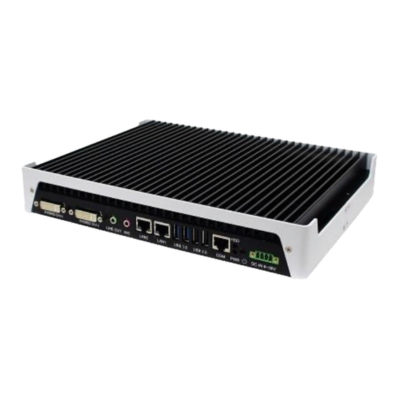
ULT Processors with Intel graphics engine integrated. Featuring a wide-operating temperature range from -40°C to 75°C and 7V to 36V wide-range DC input, the SE-602-N is built specifically for harsh environments in-vehicle applications. The integrated dual DVI-I interface supports either a DVI-D or VGA display and has built-in EDID emulation function(**). -
Page 10: System Specifications
SE-602-N User Manual 1.2 System Specifications 1.2.1 Hardware Specifications Model Name SE-602-N System Mainboard MBD602 5th Generation Intel® Core™ i7-5650U ULT 2.2GHz 5th Generation Intel® Core™ i5-5350U ULT 1.8GHz Memory 2x DDR3L-1600 SO-DIMM Max. 16GB 2x DVI-I with EDID emulation function 2x USB 2.0... -
Page 11: Dimensions
IBASE Technology Inc. 1.2.2 Dimensions Copyright © 2013 IBASE Technology Inc. All Rights Reserved. -
Page 12: I/O View
SE-602-N User Manual 1.2.3 I/O View SE-602-N front side SE-602-N rear side... - Page 13 IBASE Technology Inc. **Based on the design of SE-602-N, the use of DVI port has certain limitations. In “ ” order to have an image on the screen, the odd number port should be plugged “ ” in first. If the...
-
Page 14: Exploded View Of The Se-602-N Assembly
SE-602-N User Manual 1.3 Exploded View of the SE-602-N Assembly 1.3.1 Parts Description Part No. Description Part No. Description MBD602 motherboard SE-602-N_perimeter SE-602-N_rear cover SE-602-N_front cover SCREW-B30 SCREW-B30-B NUTBOSS-S6 SE-602-N_heat sink SE-602-N_ic heat sink_2 SE-602-N_hdd bracket SE-602-N_HDD tray SE-602-N_HDD cover... -
Page 15: Packing List
EXT-312 (C501EXT3120A12000P) Power adapter/cable Description P/S;ADAPTER 150W 12V 4PIN W/LOCK [FSP150-AHAN2] RoHS 150W power adapter (A005PS150W0313000P) 4 pin external power CABLE;EXT-532 2-HD 30CM MINI-DIN 4-pin => EC350VM 04P+SW cable RoHS (C501EXT5320302000P) Copyright © 2013 IBASE Technology Inc. All Rights Reserved. - Page 16 SE-602-N User Manual ** Power adapter connection [Important] If you shutoff the electric switch, DO NOT push the power button of the external power cable at the same time. Otherwise, it will send a wrong signal.
-
Page 17: Hardware Installation
IBASE Technology Inc. 1.5 HARDWARE INSTALLATION 1.5.1 Mounting Installation 1. Please install SE-602-N to the desired location using 6 screws, as shown in the picture. Copyright © 2013 IBASE Technology Inc. All Rights Reserved. -
Page 18: Installing The Storage
SE-602-N User Manual 1.5.2 Installing the storage 1. Remove the two screws on the HDD cover and draw it out. 2. Install the HDD/SSD to the HDD bracket with 4 screws. -
Page 19: Chapter 2 Motherboard Introduction
IBASE Technology Inc. CHAPTER 2 MOTHERBOARD INTRODUCTION 2.1 Introduction MBD602 Jumpers and Connectors Copyright © 2013 IBASE Technology Inc. All Rights Reserved. - Page 20 SE-602-N User Manual MBD602 Board Dimensions...
-
Page 21: Installations
2. Gently push the DDR3 module in an upright position until the clips of the slot close to hold the DDR3 module in place when the DDR3 module touches the bottom of the slot. 3. To remove the DDR3 module, press the clips with both hands. Copyright © 2013 IBASE Technology Inc. All Rights Reserved. -
Page 22: Jumpers And Connectors
SE-602-N User Manual 2.3 Jumpers and Connectors CN3: USB3 #2 CN4: USB3 #1 CN5: I210 Gigabit LAN CN6: I218LM Gigabit LAN CN7: COM1 CN8: USB2 #4 CN9: USB2 #5 CN10: LINE OUT CN11: MIC IN CN12: DVI-I CN13: DVI-I LED5: Power LED... - Page 23 DDC CLOCK DATA 5+ DDC DATA SHIELD CLK CLOCK - DATA 1- CLOCK + DATA 1+ SHIELD 1/3 DATA 3- DATA 3+ DDC POWER A GROUND2 A GROUND 1 A GROUND3 Copyright © 2013 IBASE Technology Inc. All Rights Reserved.
- Page 24 SE-602-N User Manual J11: Power Connector Pin # Signal Name DC-IN EARTH GND IGS-IN J3: Clear ME Contents Setting Function Pin 1-2 Normal Short/Closed Pin 2-3 Clear CMOS Short/Closed J2: Clear CMOS Contents Setting Function Pin 1-2 Normal Short/Closed Pin 2-3...
-
Page 25: Chapter 3 Bios Setup
<PgDn> keys to change entries, <F1> for help and <Esc> to quit. When you enter the Setup utility, the Main Menu screen will appear on the screen. The Main Menu allows you to select from various setup functions and exit choices. Copyright © 2013 IBASE Technology Inc. All Rights Reserved. - Page 26 SE-602-N User Manual Main Settings Aptio Setup Utility – Copyright © 2011 American Megatrends, Inc. Main Advanced Chipset Boot Security Save & Exit Choose the system default language Total memory 4096 MB (DDR3) Memory Frequency 1600 Mhz → ← Select Screen...
- Page 27 Enter: Select ► NCT5523D H/W Monitor +- Change Field F1: General Help ► SATA Configuration F2: Previous Values F3: Optimized Default ► CSM Configuration F4: Save ESC: Exit ► USB Configuration Copyright © 2013 IBASE Technology Inc. All Rights Reserved.
- Page 28 SE-602-N User Manual CPU Configuration Aptio Setup Utility Advanced Main Chipset Boot Security Save & Exit CPU Configuration Intel(R) CPU Core(TM)i7-5650U @ 2.20GHz CPU Signature 306d4 Microcode Patch Max CPU Speed 2200 MHz Min CPU Speed 500 MHz CPU Speed...
- Page 29 Enable/Disable Security Device. NOTE: Your Computer will reboot during restart in order to change State of the Device. Pending operation Schedule an Operation for the Security Device. NOTE: Your Computer will reboot during restart in order to change State of Security Device. Copyright © 2013 IBASE Technology Inc. All Rights Reserved.
- Page 30 SE-602-N User Manual ACPI Settings Aptio Setup Utility Main Advanced Chipset Boot Security Save & Exit ACPI Settings → ← Select Screen ↑↓ Select Item Enable Hibernation Enabled Enter: Select +- Change Field ACPI Sleep State S1 (CPU Stop Clock)
- Page 31 This field sets the system power status whether Disable or Enable when power returns to the system from a power failure situation. Temperature Guardian Generate the reset signal when system hangs up on POST. Schedule Slot 1 / 2 Setup the hour/minute for system power on. Copyright © 2013 IBASE Technology Inc. All Rights Reserved.
- Page 32 SE-602-N User Manual AMT Configuration Aptio Setup Utility Advanced Main Chipset Boot Security Save & Exit Intel AMT Enabled BIOS Hotkey Pressed Disabled MEBx Selection Screen Disabled Hide Un-Configure ME Confirmation Disabled → ← Amt Wait Timer Select Screen ↑↓ Select Item...
- Page 33 Temperatures/Voltages These fields are the parameters of the hardware monitoring function feature of the board. The values are read-only values as monitored by the system and show the PC health status. Copyright © 2013 IBASE Technology Inc. All Rights Reserved.
- Page 34 SE-602-N User Manual SATA Configuration SATA Devices Configuration. Aptio Setup Utility Advanced Main Chipset Boot Security Save & Exit SATA Controller(s) Enabled SATA Mode Selection AHCI SATA Controller Speed Default SATA Port0 Empty Software Preserve Unknown Port 0 Enabled Hot Plug...
- Page 35 Controls the execution of UEFI and Legacy Storage OpROM. Video Controls the execution of UEFI and Legacy Video OpROM. Other PCI device Determines OpROM execution policy for devices other than Network, Storage, or Video Copyright © 2013 IBASE Technology Inc. All Rights Reserved.
- Page 36 SE-602-N User Manual USB Configuration Aptio Setup Utility Advanced Main Chipset Boot Security Save & Exit USB Configuration USB Module Version 8.11.02 USB Devices: 1 Keyboard, 1 Mouse Legacy USB Support Enabled → ← Select Screen XHCI Hand-off Enabled ↑↓ Select Item...
- Page 37 ↑↓ Select Item Enter: Select +- Change Field F1: General Help VT-d Enabled F2: Previous Values F3: Optimized Default F4: Save ESC: Exit VT-d Check to enable VT-d function on MCH. Copyright © 2013 IBASE Technology Inc. All Rights Reserved.
- Page 38 SE-602-N User Manual PCH-IO Configuration This section allows you to configure the North Bridge Chipset. Aptio Setup Utility Chipset Main Advanced Boot Security Save & Exit Intel PCH RC Version 2.2.2.0 Intel PCH SKU Name Premium SKU(BDW-U) Intel PCH Rev ID 03/B2 ►...
- Page 39 Control Detection of the Azalia device. Disabled = Azalia will be unconditionally be disabled. Enabled = Azalia will be unconditionally be enabled. Auto = Azalia will be enabled if present, disabled otherwise. Copyright © 2013 IBASE Technology Inc. All Rights Reserved.
- Page 40 SE-602-N User Manual Security Settings This section allows you to configure and improve your system and allows you to set up some system features according to your preference. Aptio Setup Utility Security Main Advanced Chipset Boot Save & Exit Password Description If ONLY the Administrator’s password is set, then...
- Page 41 Enables/Disables boot with initialization of a minimal set of devices required to launch active boot option. Has no effect for BBS boot options. Boot mode select Select boot mode LEGACY/UEFI FIXED BOOT ORDER Priorities Sets the system boot order. Copyright © 2013 IBASE Technology Inc. All Rights Reserved.
- Page 42 SE-602-N User Manual Save & Exit Settings Advanced Main Chipset Boot Security Save & Exit Save Changes and Exit Discard Changes and Exit Save Changes and Reset Discard Changes and Reset → ← Save Options Select Screen Save Changes ↑↓ Select Item...
-
Page 43: Chapter 4 Drivers Installation
Software Installation Utility before proceeding with the drivers installation. 4.1 Intel Chipset Software Installation Utility 1. Insert the DVD that comes with the board. Click System and then SE-602-N Series Products. 2. Click Intel(R) Chipset Software Installation Utility. Copyright © 2013 IBASE Technology Inc. All Rights Reserved. - Page 44 SE-602-N User Manual 3. When the Welcome screen to the Intel® Chipset Device Software appears, click Next to continue. 4. Click Accept to accept the software license agreement and proceed with the installation process.
- Page 45 5. On the Readme File Information screen, click Install to continue the installation. 6. The Setup process is now complete. Click Finish to restart the computer and for changes to take effect. Copyright © 2013 IBASE Technology Inc. All Rights Reserved.
- Page 46 SE-602-N User Manual 4.2 VGA Drivers Installation 1. Insert the DVD that comes with the board. Click System and then SE-602-N Series Products. 2. Click Intel(R) Broadwell Graphics Driver.
- Page 47 IBASE Technology Inc. 3. When the Welcome screen appears, click Next to continue. 4. When the License Agreement, click Next to continue. Copyright © 2013 IBASE Technology Inc. All Rights Reserved.
- Page 48 SE-602-N User Manual 5. Click Next to to agree with the license agreement and continue the installation.
- Page 49 IBASE Technology Inc. 6. Setup Progress. Click Next to restart the computer and for changes to take effect. 7. Setup complete. Click Finish to restart the computer and for changes to take effect Copyright © 2013 IBASE Technology Inc. All Rights Reserved.
- Page 50 SE-602-N User Manual 4.3 Realtek HD Audio Driver Installation 1. Insert the DVD that comes with the board. Click System and then SE-602-N Series Products. 2. Click Realtek High Definition Audio Driver.
- Page 51 3. On the Welcome to the InstallShield Wizard screen, click Yes to proceed with and complete the installation process. 4. The InstallShield Wizard Complete. Click Finish to restart the computer and for changes to take effect. Copyright © 2013 IBASE Technology Inc. All Rights Reserved.
- Page 52 SE-602-N User Manual 4.4 LAN Drivers Installation 1. Insert the DVD that comes with the board. Click System and then SE-602-N Series Products. 2. Click Intel(R) PRO LAN Network Driver.
- Page 53 IBASE Technology Inc. 3. When the Welcome screen appears, click Next. 4. Click Next to to agree with the license agreement. Copyright © 2013 IBASE Technology Inc. All Rights Reserved.
- Page 54 SE-602-N User Manual 5. Click the checkbox for Drivers in the Setup Options screen to select it and click Next to continue. 6. The wizard is ready to begin installation. Click Install to begin the installation. 7. When InstallShield Wizard is complete, click Finish.
- Page 55 After installing your Windows operating system, you must install first the Kernel-Mode Driver Framework (KMDF) 1.11 KB2685811 patch before installing Intel(R) Management Engine(ME) Driver. 1. Insert the DVD that comes with the board. Click System and then SE-602-N Series Products. 2. Click Intel(R) Management Engine(ME) Driver...
- Page 56 SE-602-N User Manual 3. When the Welcome screen to the InstallShield Wizard for Intel® Management Engine Components, click the checkbox for Install Intel® Control Center & click Next. 4. Click Next to to agree with the license agreement.
- Page 57 IBASE Technology Inc. 5. When the Destination Folder, click Next. Then, click Finish when the setup progress has been successfully installed. Copyright © 2013 IBASE Technology Inc. All Rights Reserved.
- Page 58 SE-602-N User Manual 4.6 Intel® USB 3.0 Drivers 1. Insert the DVD that comes with the board. Click System and then SE-602-N Series Products. 2. Click Intel(R) USB3.0 eXtensible Host Controller Driver...
- Page 59 3. When the Welcome screen to the InstallShield Wizard for Intel® USB 3.0 eXtensible Host Controller Driver, click Next. 4. Click Yes to to agree with the license agreement and continue the installation. Copyright © 2013 IBASE Technology Inc. All Rights Reserved.
- Page 60 SE-602-N User Manual 5. On the Readme File Information screen, click Next to continue the installation of the Intel® USB 3.0 eXtensible Host Controller Driver. 6. Setup complete. Click Finish to restart the computer and for changes to take effect.
- Page 61 After installing the driver, please go to the page “Windows Control Panel -> All Control Panel Items -> Power Options -> System Settings”. Please set the “When I press the power button” item default to “shutdown”. Copyright © 2013 IBASE Technology Inc. All Rights Reserved.
-
Page 62: Appendix
SE-602-N User Manual Appendix A. I/O Port Address Map Each peripheral device in the system is assigned a set of I/O port addresses which also becomes the identity of the device. The following table lists the I/O port addresses used. - Page 63 The following table shows the IRQ used by the devices on board. Level Function IRQ0 System Timer Output IRQ1 Keyboard IRQ3 Serial Port #2 IRQ4 Serial Port #1 IRQ5 SMBus Controller IRQ8 Real Time Clock IRQ19 SATA AHCI Controller Copyright © 2013 IBASE Technology Inc. All Rights Reserved.
- Page 64 SE-602-N User Manual C. Watchdog Timer Configuration The WDT is used to generate a variety of output signals after a user programmable count. The WDT is suitable for use in the prevention of system lock-up, such as when software becomes trapped in a deadlock.
- Page 65 (ucDid == 0x07) //6106 {goto Init_Finish;} 6106_BASE = 0x2E; result = 6106_BASE; ucDid = Get_6106_Reg(0x20); if (ucDid == 0x07) //6106 { goto Init_Finish; } 6106_BASE = 0x00; result = 6106_BASE; Init_Finish: return (result); Copyright © 2013 IBASE Technology Inc. All Rights Reserved.
- Page 66 SE-602-N User Manual //--------------------------------------------------------------------------- void Unlock_6106 (void) outportb(6106_INDEX_PORT, 6106_UNLOCK); outportb(6106_INDEX_PORT, 6106_UNLOCK); //--------------------------------------------------------------------------- void Lock_6106 (void) outportb(6106_INDEX_PORT, 6106_LOCK); //--------------------------------------------------------------------------- void Set_6106_LD( unsigned char LD) Unlock_6106(); outportb(6106_INDEX_PORT, 6106_REG_LD); outportb(6106_DATA_PORT, LD); Lock_6106(); //--------------------------------------------------------------------------- void Set_6106_Reg( unsigned char REG, unsigned char DATA) Unlock_6106(); outportb(6106_INDEX_PORT, REG);...
- Page 67 MCU provides command to get current status which includes the high voltage protection value, low voltage protection value, power on delay timer setting value, power off delay timer setting value and DC off delay timer setting value.. Copyright © 2013 IBASE Technology Inc. All Rights Reserved.
- Page 68 SE-602-N User Manual Note : Before using the ISP, the software engineer have to make sure the firmware version (GET_FORMWARE_VERSION) MUST be major version is 0 and minor version is 0 and build version is 1(or above), otherwise the ISP function will not works.
- Page 69 Size specifies number of bytes for data field. Command identifies action, which is required to be performed on the data. CRC verifies data integrity for header, size, command and data bytes. Copyright © 2013 IBASE Technology Inc. All Rights Reserved.
- Page 70 SE-602-N User Manual 1.2.3 CRC Protocol uses 16-bit CCITT CRC to verify data integrity. P(x) = X unsigned calc_crc(unsigned char *data, unsigned unsigned start) { unsigned I, k, q, c, crcval; crcval=start; (I=0; I<n; I++) { c=data(I) & 0xFF; q=(crcval^c) & 0x0F;...
- Page 71 Master-Slave model, where PC is a master, and Security MCU is a slave. Master sends requests to the slave, and slave has to reply to them. Slave acts like a passive device and cannot send any requests to the master. Copyright © 2013 IBASE Technology Inc. All Rights Reserved.
- Page 72 SE-602-N User Manual 1.3 Command and Reply Codes 1.3.1 Summary Code Value Description GET_FIRMWARE_VERSION 0x01 Get Firmware version SET_HYSTERSIS_HIGH 0x02 Hysteresis High Voltage setting SET_HYSTERSIS_LOW 0x03 Hysteresis Low Voltage setting SET_POWER_ON_DELAY_TIMER 0x04 Power on delay timer setting SET_POWER_OFF_DELAY_TIMER 0x05 Power off delay timer setting...
- Page 73 Ex. Setting 11.2V mapping to 11200 (11.2x1000) = 2BC0(hex) Data0 = 2B(hex) Data1 = C0(hex) The tolerance for the temperature measurement is plus and minus 0.3 Volts. Reply Header Size Command Data 0xFF 0x00 SET_HYSTERSIS_HIGH None 0xEE Copyright © 2013 IBASE Technology Inc. All Rights Reserved.
- Page 74 SE-602-N User Manual 1.3.4 Set hysteresis low voltage SET_HYSTERESIS_LOW_VOLTAGE Hysteresis Low Voltage setting . Request Header Size Command Data0 Data1 0xFF 0x02 SET_HYSTERSIS_LOW High Byte Low Byte 0xEE Round off to the 1st decimal place. Ex. Setting 11.2V mapping to 11200 (11.2x1000) = 2BC0(hex)
- Page 75 0x02 SET_DC_OFF_DELAY_TIMER N 0xEE (Minutes) (seconds) Reply Header Size Command Data 0xFF 0x00 SET_DC_OFF_DELAY_TIMER None 0xEE 1.3.8 Get Status Get the current hysteresis high voltage, hysteresis low voltage, power_on_delay_timer, power_off_delay_timer and power_off_delay_timer. Copyright © 2013 IBASE Technology Inc. All Rights Reserved.
- Page 76 SE-602-N User Manual Request Header Size Command Data 0xFF 0x00 GET_STATUS None 0xEE Reply Header Size Command Data 0xFF GET_STATUS Status structure 0xEE Status Structure Field Type Description Hysteresis high voltage Word Byte0+ Byte1 Hysteresis low voltage Word Byte2+ Byte3...
Need help?
Do you have a question about the SE-602-N and is the answer not in the manual?
Questions and answers