Table of Contents
Advertisement
Quick Links
Advertisement
Table of Contents

Related Manuals for IBASE Technology SI-334


Summary of Contents for IBASE Technology SI-334
- Page 1 SI-334 Mid-Range Digital Signage Player User’s Manual Version 1.0 (February 2022)
- Page 2 No part of this publication may be reproduced, copied, stored in a retrieval system, translated into any language or transmitted in any form or by any means, electronic, mechanical, photocopying, or otherwise, without the prior written consent of IBASE Technology, Inc. (hereinafter referred to as “IBASE”).
- Page 3 0.1% by weight (1000 ppm) except for cadmium, limited to 0.01% by weight (100 ppm). • Lead (Pb) • Mercury (Hg) • Cadmium (Cd) • Hexavalent chromium (Cr6+) • Polybrominated biphenyls (PBB) • Polybrominated diphenyl ether (PBDE) SI-334 User Manual...
- Page 4 Avoid Disassembly Do not disassemble, repair or make any modification to the device. Doing so could generate hazards and cause damage to the device, even bodily injury or property damage, and will void any warranty. SI-334 User Manual...
- Page 5 Software in use (such as OS and application software, including the version numbers) 3. If repair service is required, you can download the RMA form at http://www.ibase.com.tw/english/Supports/RMAService/. Fill out the form and contact your distributor or sales representative. SI-334 User Manual...
-
Page 6: Table Of Contents
Jumper & Connector Locations on Motherboard ........15 Jumpers & Connectors Reference ............17 Chapter 3 Driver Installation ..............32 Introduction ................... 33 AMD Radeon™ Graphics Driver Installation.......... 33 HD Audio Driver Installation ..............34 LAN Driver Installation ................35 SI-334 User Manual... - Page 7 Setting Up AMD Eyefinity Using Quick Setup ......58 Customizing AMD Eyefinity Using Try Advanced Setup ..62 I/O Port Address Map ................68 Interrupt Request Lines (IRQ) ............... 70 Watchdog Timer Configuration .............. 72 AMD Eyefinity Mode Display Setting Configurations ......76 SI-334 User Manual...
-
Page 9: Chapter 1 General Information
Chapter 1 General Information The information provided in this chapter includes: • Features • Packing List • Accessories • Specifications • Product View • Dimensions... -
Page 10: Introduction
1.1 Introduction The SI-334 is a digital signage player harnessing the performance of an AMD Ryzen™ Embedded V2748B with Radeon™ Graphics that provides 40 percent better graphics output over the previous generation. The compact video wall player enhances in-store shopping experience in modern retail with eye-catching, engaging displays. -
Page 11: Features
Your product package should include the items listed below. If any of the items below is missing, contact the distributor or the dealer from whom you purchased the product. • SI-334 Digital Signage Player • Power Adapter • Power Cord 1.4 Optional Accessories... -
Page 12: Specifications
SGCC, black & white Mounting Slim design with wall mount holes Dimensions 269mm(W) x 193mm(D) x 31.5mm(H) 10.59”(W) x 7.59”(D) x 1.24”(H) (W x H x D) Net Weight 2.1 kg (4.63 lb) Certificate CE, FCC class A, cULus, CCC SI-334 User Manual... - Page 13 General Information Environment • Operating: 0 ~ 45 °C (32 ~ 113 °F) Temperature • Storage: -20 ~ 80 °C (-4 ~ 176 °F) Relative 10 ~ 90% at 45 °C (non-condensing) Humidity Vibration M.2 card: random operation 5grms, 5~500 Hz Protection All specifications are subject to change without prior notice.
-
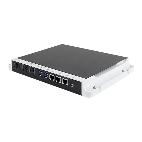
Page 14: Product View
1.6 Product View Front View Name Name DC Power Input GbE LAN Ports Power Button COM Port HDMI Ports Audio Line-Out Jack USB 3.0 Ports Oblique View SI-334 User Manual... -
Page 15: Dimensions
General Information 1.7 Dimensions Unit: mm SI-324 User Manual... -
Page 16: Hardware Installation & Motherboard Information
Chapter 2 Hardware Installation & Motherboard Information The information provided in this chapter includes: • Installation of memory and M.2 cards • Information and locations of connectors... -
Page 17: Installation / Replacement
1 memory module, M.2 M2280 & E2230 cards, and SIM card. If you need to install or replace the M.2 module, perform the following steps. 1. Remove the following 3 screws to remove the M.2 heatsink. SI-334 User Manual... -
Page 18: Memory
To remove the module, press the ejector tabs outwards with your fintertips to eject the module. NOTE: 4K video requires two pieces of DDR4-3200 (Min. 4GB) memory modules. SI-334 User Manual... -
Page 19: Cards
Then install the antenna. Info: The diameter of the nut is around 6.35 mm (0.25”-36UNC). Remarks: M.2 B-Key (3052) supports interface PCIe or USB. The standard SI-334 supports interface PCIe. If you need a USB interface, please contact your supplier. -
Page 20: Mounting Installation
1U Rackmount Installation (Optional) As shown below, to install the device on the rackmount tray, there are a total of 10 screws that will be used (four screws to install the device and six screws to install the mounting handles). SI-334 User Manual... -
Page 21: Pin Assignment For Dc Power Input Connector
Hardware Configuration 2.2 Pin Assignment for DC Power Input Connector ➔ Assignment Assignment Ground Ground +12V +12V SI-334 User Manual... -
Page 22: Setting The Jumpers
2.3 Setting the Jumpers Set up and configure your SI-334 by using jumpers for various settings and features according to your needs and applications. Contact your supplier if you have doubts about the best configuration for your use. 2.4.1 How to Set Jumpers Jumpers are short-length conductors consisting of several metal pins with a non-conductive base mounted on the circuit board. -
Page 23: Jumper & Connector Locations On Motherboard
Hardware Configuration 2.4 Jumper & Connector Locations on Motherboard Motherboard: MBD334 MBD334 – top and I/O SI-334 User Manual... - Page 24 MBD334 - bottom SI-334 User Manual...
-
Page 25: Jumpers & Connectors Reference
EDID Emulator MCU Programming Header SPI Flash Connector LPC Debug Port Connector Front Panel Settings Connector ISMART MCU Programming Header NGFF_M.2_B-Key 3052 Nano SIM Card Slot CN11 NGFF_M.2_E-Key 2230 M.2 (M-Key) 2280 Slot CPU Fan Connector CPU_FAN1 System Fan Connector SYS_FAN1 SI-334 User Manual... - Page 26 2.5.1 JBAT1: Clear CMOS Setting Function Pin closed Illustration Normal (default) Clear CMOS 2.5.2 JP1: EDID Emulator MCU Functions Function Pin closed Illustration Enable EDID Bypass EDID SI-334 User Manual...
- Page 27 Hardware Configuration 2.5.3 JP2: ATX / AT Power Selection Function Pin closed Illustration ATX Mode AT Mode SI-334 User Manual...
- Page 28 2.5.4 JP3: COM1/ RS232 RI/+5V/+12V Power Setting Function Illustration +12V Pin 1-3 Short Pin 3-4 Short Pin 3-5 Short SI-334 User Manual...
- Page 29 Hardware Configuration 2.5.5 CN1: DC_IN Connector (+12V Adaptor 4 Pin) Signal Name +12V +12V 2.5.6 SW1: Power Button SI-334 User Manual...
- Page 30 2.5.7 CN2 / CN3 / CN4 / CN5: HDMI Ports SI-334 User Manual...
- Page 31 Hardware Configuration 2.5.8 CN6: USB2.0 (top) / USB3.1 (bottom) 2.5.9 CN7: USB 3.1 Ports SI-334 User Manual...
- Page 32 Signal Name Signal Name DSR, Data set ready DCD, Data carrier detect GND, ground DTR, Data terminal ready GND, ground CTS, Clear to send TXD, Transmit data RTS, Request to send RXD, Receive data RI, Ring indicator SI-334 User Manual...
- Page 33 Hardware Configuration 2.5.12 CN10: Audio Line Out 2.5.13 SW2: EDID Clear Button SI-334 User Manual...
- Page 34 2.5.14 J1: EDID Emulator MCU Programming Header 2.5.15 J3: SPI Flash Connector SI-334 User Manual...
- Page 35 Hardware Configuration 2.5.16 J4: LPC Debug Port Connector 2.5.17 J5: Front Panel Settings Connector Signal Name Signal Name Power BTN- Power BTN+ HDD LED+ HDD LED- Reset BTN- Reset BTN+ Power LED+ Power LED- SI-334 User Manual...
- Page 36 2.5.18 J6: ISMART MCU Programming Header 2.5.19 J7: NGFF_M.2_B-Key 3052 J7 supports USB 3.1 & PCIE (1x) & SIM card. SI-334 User Manual...
- Page 37 Hardware Configuration 2.5.20 CN11: Nano SIM Card Slot 2.5.21 J8: NGFF_M.2_E-Key 2230 J8 supports USB2.0 & PCIE(1x). SI-334 User Manual...
- Page 38 2.5.22 J9: M.2 (M-Key) 2280 Slot J9 supports NVMe/ PCIe (4x) & SATA. 2.5.23 CPU_FAN1: CPU Fan Connector SI-334 User Manual...
- Page 39 Hardware Configuration 2.5.24 SYS_FAN1: System Fan Connector SI-334 User Manual...
-
Page 40: Chapter 3 Driver Installation
Chapter 3 Driver Installation The information provided in this chapter includes: • AMD Radeon™ Graphics Driver Installation • HD Audio Driver Installation • LAN Driver Installation... -
Page 41: Introduction
3.2 AMD Radeon™ Graphics Driver Installation 1. Run the Setup.exe file. 2. Accept the license agreement to continue. 3. Choose either Express Install or Custom Install. 4. When the driver is completely installed, restart the computer for changes to take effect. SI-334 User Manual... -
Page 42: Hd Audio Driver Installation
3.3 HD Audio Driver Installation 1. Run the Setup.exe file. 2. On the Welcome screen of the InstallShield Wizard, click Next for installation. 3. When the driver is completely installed, restart the computer for changes to take effect. SI-334 User Manual... -
Page 43: Lan Driver Installation
1. Run the Setup.exe file. 2. On the Welcome screen of the InstallShield Wizard, click Next. 3. Accept the license agreement and click Next to continue. 4. When the driver is completely installed, restart the computer for changes to take effect. SI-334 User Manual... -
Page 44: Chapter 4 Bios Setup
Chapter 4 BIOS Setup This chapter describes the different settings available in the AMI BIOS that comes with the board. The topics covered in this chapter are as follows: • Main Settings • Advanced Settings • Chipset Settings • Security Settings •... -
Page 45: Introduction
These defaults have been carefully chosen by both AMI and your system manufacturer to provide the absolute maximum performance and reliability. Changing the defaults could make the system unstable and crash in some cases. SI-334 User Manual... -
Page 46: Main Settings
Set the time. Use the <Tab> key to switch between the data elements. 4.4 Advanced Settings This section allows you to configure, improve your system and allows you to set up some system features according to your preference. SI-334 User Manual... - Page 47 TPM 1.2 will restrict support to TPM 1.2 devices. TPM 2.0 will restrict support to TPM 2.0 devices. Device Select Auto will support both with the default set to TPM 2.0 devices if not found, TPM 1.2 devices will be enumerated. SI-334 User Manual...
- Page 48 Enables / Disables system ability to hibernate (OS/S4 Sleep State). This option may not be effective with some operating systems. ACPI Sleep State Selects the highest ACPI sleep state the system will enter when the SUSPEND button is pressed. SI-334 User Manual...
- Page 49 For example, if setting up a schedule from Wednesday 5 p.m. to Thursday 2 a.m., configure two schedule slots. But if setting up a schedule from 3 p.m to 5 p.m. on Wednesday, configure only a schedule slot. SI-334 User Manual...
- Page 50 4.4.4 F81804 Super IO Configuration BIOS Setting Description Serial Ports Configuration Sets parameters of Serial Port (COM). Enables / Disables the serial port and select an optimal setting for the Super IO device. SI-334 User Manual...
- Page 51 50°C, 60°C, 70°C or 80°C. Temperatures / Voltages These fields are the parameters of the hardware monitoring function feature of the motherboard. The values are read-only values as monitored by the system and show the PC health status. SI-334 User Manual...
- Page 52 4.4.6 CPU Configuration BIOS Setting Description Node 0 Information Displays the memory information related to Node 0. SI-334 User Manual...
- Page 53 BIOS Setup 4.4.7 IDE Configuration 4.4.8 AMI Graphics Output Protocol Policy BIOS Setting Description Output Selection Selects an output interface. SI-334 User Manual...
- Page 54 The maximum time the device will take before it properly reports itself to the Host Controller. “Auto” uses default value for a Root port it is 100ms. But for a Hub port, the delay is taken from Hub descriptor. SI-334 User Manual...
- Page 55 PXE boot. Use either +/1 or numeric keys to set the value Media detect count Number of times the presence of media will be checked. Use either +/- or numeric keys to set the value SI-334 User Manual...
- Page 56 4.4.11 NVMe Configuration SI-334 User Manual...
- Page 57 BIOS Setup 4.4.12 AMD CBS SI-334 User Manual...
-
Page 58: Chipset Settings
4.5 Chipset Settings BIOS Setting Description Sourth Bridge South Bridge parameters SB USB Configuration Options for SB USB configuration. SI-334 User Manual... - Page 59 BIOS Setup 4.5.1 SB USB Configuration BIOS Setting Description XHCI0 / XHCI1 Ports Enables / Disables XHCI0 / XHCI1 ports. SI-334 User Manual...
-
Page 60: Security Settings
4.6 Security Settings BIOS Setting Description Administrator Password Sets an administrator password for the setup utility. User Password Sets a user password. Secure Boot Customizable secure boot settings. SI-334 User Manual... - Page 61 System mode is user deployed, and CSM is disabled. Secure Boot Customizable Secure Boot mode: In Custom Customization mode, Secure Boot policy variables can be configured by a physically present user without full authentication. Options: Standard, Custom SI-334 User Manual...
-
Page 62: Boot Settings
Enables / Disables Quiet Boot option. Boot Mode Select Select boot mode as Legacy or UEFI. Boot Option Priorities Sets the system boot order. UEFI Hard Disk Drive Specifies the Boot device priority sequence from BBS Priorities available UEFI hard disk drives. SI-334 User Manual... -
Page 63: Save & Exit Settings
Restore Defaults Restores / Loads defaults values for all the setup options. Save as User Defaults Saves the changes done so far as user defaults. Restore User Defaults Restores the user defaults to all the setup options. SI-334 User Manual... -
Page 64: Appendix
Appendix This section provides the mapping addresses of peripheral devices and the sample code of watchdog timer configuration. • SDR and HDR Resolution Support • AMD Eyefinity Multiple Displays • I/O Port Address Map • Interrupt Request Lines (IRQ) • Watchdog Timer Configuration... -
Page 65: Sdr And Hdr Resolution Support
Dual Channel: • 2 displays: 2160p60 • 4 displays: 1440p60 Single Channel: • 1 display: 2160p60 • 2 displays: 1440p60 • 4 displays: 1080p60 Note: This is about the supported display resolution, not related to the multimedia streams. SI-334 User Manual... -
Page 66: Amd Eyefinity Multiple Displays Configuration
AMD Eyefinity Multiple Displays Configuration AMD Eyefinity is applicable to SI-334; it is a technology that allows two or more displays to be grouped together to form a single large desktop. Once AMD Eyefinity is configured, the final resolution is the horizontal and/or vertical sum of the individual monitors. - Page 67 However, this feature is not supported. Do not confuse with Try Advanced Setup (see below picture), which becomes available after Eyefinity Quick Setup is complete. The Try Advanced Setup option is used to customize the Eyefinity Display Group created after Eyefinity Quick Setup is complete. SI-334 User Manual...
- Page 68 Eyefinity Display Group. Refer to B.2 Customizing AMD Eyefinity Using Try Advanced Setup for details. Arrange Displays after Eyefinity Quick Setup To arrange displays in desired positions (optional): 1. Click Arrange Displays after Eyefinity Quick Setup is complete. SI-334 User Manual...
- Page 69 (i.e. Eyefinity Display Group + Extended Desktop Displays). In this example, physically connect 3 of the 4 displays first and arrange them in 3 x 1 extended desktop in the Operating System’s display settings. SI-334 User Manual...
-
Page 70: Customizing Amd Eyefinity Using Try Advanced Setup
Eyefinity Display Group or in one preferred display. By default, the Taskbar extends across all displays in a single row AMD Eyefinity Display Group. In a multi-row AMD Eyefinity Display Group, it extends across the bottom row of displays. SI-334 User Manual... - Page 71 4. To move the Taskbar, simply drag and drop it to the desired display. Ensure that the Taskbar setting is not set to “locked”. 5. To have the Taskbar running across multiple displays again, uncheck the Position the Windows taskbar on a single display option and click Continue. SI-334 User Manual...
- Page 72 Desktop option changes how the desktop image is shown across the displays by resizing it. To resize the desktop: 1. Click Try Advanced Setup (under Eyefinity tab in AMD Radeon Settings) after Eyefinity Quick Setup is complete. 2. Click Resize Desktop once Radeon Additional Settings launches. SI-334 User Manual...
- Page 73 Eyefinity Quick Setup is complete. 2. Click Adjust Bezel Compensation once Radeon Additional Settings launches. 3. Use the Chevrons (arrow heads) to move the triangle test pattern until it is properly aligned (as shown in below picture). SI-334 User Manual...
- Page 74 To customize Eyefinity desktop resolution: 1. Click Try Advanced Setup (under Eyefinity tab in AMD Radeon Settings) after Eyefinity Quick Setup is complete. 2. Click Customize Eyefinity Desktop Resolution once Radeon Additional Settings launches. SI-334 User Manual...
- Page 75 4. Select the preferred resolution from the Custom Resolution drop-down menu, and click Apply to save the setting. Open the Operating System’s display settings menu to change the resolution to the Custom Resolution selected in Step #4. SI-334 User Manual...
-
Page 76: I/O Port Address Map
PCI Express Root Port 0x0000E000-0x0000EFFF Realtek PCIe GBE Family Controller 0x00000040-0x00000043 System timer 0x00000010-0x0000001F Motherboard resources 0x00000022-0x0000003F Motherboard resources 0x00000063-0x00000063 Motherboard resources 0x00000065-0x00000065 Motherboard resources 0x00000067-0x0000006F Motherboard resources 0x00000072-0x0000007F Motherboard resources 0x00000080-0x00000080 Motherboard resources 0x00000084-0x00000086 Motherboard resources SI-334 User Manual... - Page 77 0x00000B20-0x00000B3F Motherboard resources 0x00000900-0x0000090F Motherboard resources 0x00000910-0x0000091F Motherboard resources 0x00000061-0x00000061 System speaker 0x00000081-0x00000083 Direct memory access controller 0x00000087-0x00000087 Direct memory access controller 0x00000089-0x0000008B Direct memory access controller 0x0000008F-0x0000008F Direct memory access controller 0x000000C0-0x000000DF Direct memory access controller SI-334 User Manual...
-
Page 78: Interrupt Request Lines (Irq)
IRQ 54 AMD High Definition Audio Controller IRQ 54 Microsoft ACPI-Compliant System IRQ 4294967285 AMD Radeon(TM) Vega 11 Graphics IRQ 4294967284 AMD Radeon(TM) Vega 11 Graphics IRQ 4294967283 AMD Radeon(TM) Vega 11 Graphics IRQ 55 Microsoft ACPI-Compliant System SI-334 User Manual... - Page 79 AMD USB 3.10 eXtensible Host Controller - 1.10 (Microsoft) IRQ 4294967268 AMD USB 3.10 eXtensible Host Controller - 1.10 (Microsoft) IRQ 4294967267 AMD USB 3.10 eXtensible Host Controller - 1.10 (Microsoft) IRQ 4294967289 AMD PSP 10.0 Device IRQ 4294967288 AMD PSP 10.0 Device SI-334 User Manual...
-
Page 80: Watchdog Timer Configuration
Fintek 81846, program abort.\n"); return(1); }//if (SIO == 0) if (argc != 2) printf(" Parameter incorrect!!\n"); return (1); bTime = strtol (argv[1], endptr, 10); printf("System will reset after %d seconds\n", bTime); if (bTime) EnableWDT(bTime); } else DisableWDT(); } return 0; SI-334 User Manual... - Page 81 // IMPLIED WARRANTIES OF MERCHANTABILITY AND/OR FITNESS FOR A PARTICULAR // PURPOSE. //--------------------------------------------------------------------------- #include "F81846.H" #include <dos.h> //--------------------------------------------------------------------------- unsigned int F81846_BASE; void Unlock_F81846 (void); void Lock_F81846 (void); //--------------------------------------------------------------------------- unsigned int Init_F81846(void) unsigned int result; unsigned char ucDid; SI-334 User Manual...
- Page 82 LD); Lock_F81846(); //--------------------------------------------------------------------------- void Set_F81846_Reg( unsigned char REG, unsigned char DATA) Unlock_F81846(); outportb(F81846_INDEX_PORT, REG); outportb(F81846_DATA_PORT, DATA); Lock_F81846(); //--------------------------------------------------------------------------- unsigned char Get_F81846_Reg(unsigned char REG) unsigned char Result; Unlock_F81846(); outportb(F81846_INDEX_PORT, REG); Result = inportb(F81846_DATA_PORT); Lock_F81846(); return Result; //--------------------------------------------------------------------------- SI-334 User Manual...
- Page 83 //--------------------------------------------------------------------------- #defineF81846_INDEX_PORT (F81846_BASE) #defineF81846_DATA_PORT (F81846_BASE+1) //--------------------------------------------------------------------------- #defineF81846_REG_LD 0x07 //--------------------------------------------------------------------------- #define F81846_UNLOCK 0x87 #defineF81846_LOCK 0xAA //--------------------------------------------------------------------------- unsigned int Init_F81846(void); void Set_F81846_LD( unsigned char); void Set_F81846_Reg( unsigned char, unsigned char); unsigned char Get_F81846_Reg( unsigned char); //--------------------------------------------------------------------------- #endif // F81846_H SI-334 User Manual...
-
Page 84: Amd Eyefinity Mode Display Setting Configurations
1 x 4 2 x 1 Landscape 2 x 2 3 x 1 4 x 1 1 x 2 1 x 3 1 x 4 2 x 1 Portrait 2 x 2 3 x 1 4 x 1 SI-334 User Manual...
Need help?
Do you have a question about the SI-334 and is the answer not in the manual?
Questions and answers