Table of Contents
Advertisement
Quick Links
Advertisement
Table of Contents

Related Manuals for IBASE Technology SI-313-NQC


Summary of Contents for IBASE Technology SI-313-NQC
- Page 1 SI-313 Series Digital Signage Player User’s Manual Version 1.1a (May 2018)
- Page 2 No part of this publication may be reproduced, copied, stored in a retrieval system, translated into any language or transmitted in any form or by any means, electronic, mechanical, photocopying, or otherwise, without the prior written consent of IBASE Technology, Inc. (hereinafter referred to as “IBASE”).
-
Page 3: Compliance
Compliance In a domestic environment, this product may cause radio interference in which case users may be required to take adequate measures. This product has been tested and found to comply with the limits for a Class B device, pursuant to Part 15 of the FCC Rules. These limits are designed to provide reasonable protection against harmful interference in a residential installation. -
Page 4: Important Safety Information
Important Safety Information Carefully read the precautions before using the device. Environmental conditions: • Lay the device horizontally on a stable and solid surface in case the device may fall, causing serious damage. • Leave plenty of space around the device and do not block the openings for ventilation. -
Page 5: Caution
CAUTION Danger of explosion if internal lithium-ion battery is replaced by an incorrect type. Replace only with the same or equivalent type recommended by the manufacturer. Dispose of used batteries according to the manufacturer’s instructions. Warranty Policy • IBASE standard products: 24-month (2-year) warranty from the date of shipment. -
Page 6: Table Of Contents
Table of Contents Compliance....................iii Important Safety Information ............... iv WARNING ...................... iv CAUTION ......................v Warranty Policy ....................v Technical Support & Services ..............v Chapter 1 General Information ..............1 Introduction ..................... 2 Features ....................2 Packing List .................... 3 Optional Accessories ................ - Page 7 2.5.6 LAN Port (CN5) ..............26 2.5.7 Dual USB 3.0 Ports (CN6) ............ 26 2.5.8 Dual USB 2.0 Ports (CN7) ............ 27 2.5.9 COM1 RS-232 Port (CN8) ............ 27 2.5.10 Audio Jack (CN9, CN10) ............28 2.5.11 CPU Fan Power Connector (J1) ........... 28 2.5.12 USB 2.0 Ports Header (J2) ...........
- Page 8 Appendix ...................... 55 I/O Port Address Map ................56 Interrupt Request Lines (IRQ) ............... 59 Watchdog Timer Configuration .............. 60 viii SI-313 Series User Manual...
-
Page 9: Chapter 1 General Information
Chapter 1 General Information The information provided in this chapter includes: • Features • Packing List • Specifications • Optional Accessories • Overview • Dimensions... -
Page 10: Introduction
1.1 Introduction SI-313, a product code of IBASE digital signage player series, is a mid-range system with iSmart and capable of auto-scheduling for general applications. It is designed with the feature of segregated flow ventilation. The device is powered by the AMD 3 Gen. -
Page 11: Packing List
General Information 1.3 Packing List Your product package should include the items listed below. If any of the items below is missing, contact the distributor or the dealer from whom you purchased the product. • SI-313 Series Digital Signage Player (with Rack Mount Kit) •... -
Page 12: Specifications
1.5 Specifications Product SI-313 SI-313-N System Mainboard MBD313 Windows 10 (64-bit) / 10 IoT Enterprise (64-bit) Windows 8.1+ (64-bit) Windows 7 (32-bit / 64-bit) Operating System Windows Embedded Standard 8 (32-bit / 64-bit) Windows Embedded Standard 7 (32-bit / 64-bit) Linux Open Source (64-bit) AMD 3 Gen. - Page 13 General Information Product SI-313 SI-313-N I/O Ports 3 x HDMI 2.0, choose either way: • Use 2 ports for 4K (3840 x 2160) display at 60 Hz (via HDMI 2.0) HDMI (If 3 displays are connected, the resolutions will be 4K, 4K, 1080p per the sequence of connection.) •...
-
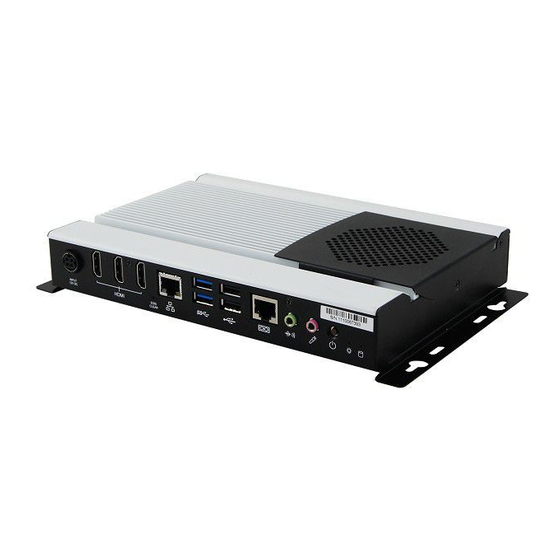
Page 14: Overview
1.6 Overview – SI-313 Top View Oblique View SI-313 Series User Manual... - Page 15 General Information I/O View No. Name Name DC Power Input Audio Line-Out HDMI 2.0 Port Microphone Input EDID Clearance Button* Power Button LAN Port LED Indicator for Power USB 3.0 LED Indicator for HDD USB 2.0 Mounting Kit COM Port Antenna Hole Be sure to press the EDID Clearance Button shortly so as to clear the EDID register when you replace the display/monitor, when the connected...
- Page 16 1.7 Overview – SI-313-N Top View Oblique View SI-313 Series User Manual...
- Page 17 General Information I/O View No. Name Name DC Power Input Audio Line-Out HDMI 2.0 Port Microphone Input EDID Clearance Button* Power Button LAN Port LED Indicator for Power USB 3.0 LED Indicator for HDD USB 2.0 Mounting Kit COM Port Antenna Hole Be sure to press the EDID Clearance Button shortly so as to clear the EDID register if any connected display/monitor is unable to be recognized, or...
-
Page 18: Dimensions
1.8 Dimensions Unit: mm SI-313: SI-313 Series User Manual... - Page 19 General Information Unit: mm SI-313-N: SI-313 Series User Manual...
-
Page 20: Hardware Installation & Motherboard Information
Chapter 2 Hardware Installation & Motherboard Information The information provided in this chapter includes: • Essential installations before you begin • Information and locations of connectors... -
Page 21: Essential Installations Before You Begin
Motherboard Information 2.1 Essential Installations Before You Begin Before you perform installations, release the following 6 screws, lift and pull out the bottom cover first. 2.1.1 Memory Installation To install the modules, locate the memory slot on the board and perform the following steps: 1. -
Page 22: Mini Pcie & M.2 Network Cards Installation
2.1.2 Mini PCIe & M.2 Network Cards Installation 1. Align the key of the mini PCIe card to the Mini PCIe interface, and insert the card slantwise. (Insert the M.2 network card in the same way.) 2. Push the mini PCIe card down, fix it with 2 screws. (Fix the M.2 network card with a screw.) Mini PCIe: M.2:... -
Page 23: Wifi / 3G / 4G Antenna Installation
Motherboard Information 2.1.3 WiFi / 3G / 4G Antenna Installation Thread the WiFi / 3G / 4G antenna extension cable through an antenna hole of the front I/O cover and fasten the antenna as shown below. Then apply adhesive to the edge of the hex nut behind the front I/O cover to prevent the extension cable from falling if the cable becomes loose. -
Page 24: Wall Mount Installation
2.1.4 Wall Mount Installation Note: Before mounting the system on wall, ensure that you are following all applicable building and electric codes. Requirements When mounting, ensure that you have enough room for power and signal cable routing, and have good ventilation for power adapter. The method of mounting must be able to support weight of the SI-313 plus the suspension weight of all the cables to be attached to the system. - Page 25 Motherboard Information Wall mount installation instructions: (This is illustrated by the example of SI-313.) Prepare at least 4 screws (M3) to install the device on wall as below. You can install your SI-313 on plastic (LCD monitor), wood, drywall surface over studs, or a solid concrete or metal plane directly.
-
Page 26: Setting The Jumpers
2.2 Setting the Jumpers Set up and configure your SI-313 by using jumpers for various settings and features according to your needs and applications. Contact your supplier if you have doubts about the best configuration for your use. 2.2.1 How to Set Jumpers Jumpers are short-length conductors consisting of several metal pins with a non-conductive base mounted on the circuit board. -
Page 27: Jumper & Connector Locations On Motherboard
Motherboard Information 2.3 Jumper & Connector Locations on Motherboard Motherboard: MBD313 Gen. Embedded R-Series SOC APU MBD313 - top SI-313 Series User Manual... - Page 28 Battery MBD313 - bottom SI-313 Series User Manual...
-
Page 29: Jumpers Quick Reference
Motherboard Information 2.4 Jumpers Quick Reference Function Connector Name Page CMOS Data Clearance ATX / AT Power Mode Selection 2.4.1 CMOS Data Clearance (JP1) Function Pin closed Illustration Normal (default) Clear CMOS SI-313 Series User Manual... -
Page 30: Atx / At Power Mode Connector (Jp2)
2.4.2 ATX / AT Power Mode Connector (JP2) Function Pin closed Illustration (default) SI-313 Series User Manual... -
Page 31: Connectors Quick Reference
Motherboard Information 2.5 Connectors Quick Reference I/O coastline connectors: Function Connector Name Page Power Button EDID Clearance Button LED Indicator LED4 (Red, for Power) LED5 (Green, for HDD) DC Power Input HDMI 2.0 Port CN2,CN3,CN4 LAN Port (GbE) Dual USB 3.0 Ports Dual USB 2.0 Ports COM1 RS-232 Port Audio Jack... -
Page 32: Power Button (Sw1)
2.5.1 Power Button (SW1) 2.5.2 EDID Clearance Button (SW2) Note: Be sure to press this button shortly so as to clear the EDID register if any connected display/monitor is unable to be recognized, or when the image displayed cannot not be resampled to fit the screen. SI-313 Series User Manual... -
Page 33: Led Indicators For Power & Hdd (Led4, Led5)
Motherboard Information 2.5.3 LED Indicators for Power & HDD (LED4, LED5) LED4 LED5 LED4 is the red LED indicator for power status. It stays on (not blinks) as the device is on. LED5 is the green LED indicator for HDD. When HDD is being read, it blinks. 2.5.4 DC Power Input (CN1) Assigment... -
Page 34: Hdmi 2.0 Port (Cn2, Cn3, Cn4)
2.5.5 HDMI 2.0 Port (CN2, CN3, CN4) 2.5.6 LAN Port (CN5) 2.5.7 Dual USB 3.0 Ports (CN6) SI-313 Series User Manual... -
Page 35: Dual Usb 2.0 Ports (Cn7)
Motherboard Information 2.5.8 Dual USB 2.0 Ports (CN7) 2.5.9 COM1 RS-232 Port (CN8) Assigment Assigment DSR (Data set ready) DCD (Data carrier detect) Ground DTR (Data terminal ready) Ground CTS (Clear to send) TX (Transmit) RTS (Request to send) RX (Receive) RI (Ring indicator) SI-313 Series User Manual... -
Page 36: Audio Jack (Cn9, Cn10)
2.5.10 Audio Jack (CN9, CN10) CN9: Line-out CN10: Microphone Input 2.5.11 CPU Fan Power Connector (J1) Assigment Ground +12V Rotation detection SI-313 Series User Manual... -
Page 37: Usb 2.0 Ports Header (J2)
Motherboard Information 2.5.12 USB 2.0 Ports Header (J2) Assigment Assigment Data- Data- Data+ Data+ Ground Ground 2.5.13 COM2 RS-232 Port (J3) Assigment Assigment DCD (Data carrier detect) DSR (Data set ready) RXD (Receive data) RTS (Request to send) TXD (Transmit data) CTS (Clear to send) DTR (Data terminal ready) RI (Ring indicator) -
Page 38: System Function Connector (J4)
2.5.14 System Function Connector (J4) Assigment Assigment Power BTN Power BTN HDD LED+ HDD LED- Reset BTN Reset BTN +5VSB 2.5.15 NGFF M.2 Connector (J6, J13) J6 is a M.2 M-Key (2280) connector with SATA. J13 is a M.2 B-Key (3042) connector with PCIe (x2) , USB 2.0, USB 3.0, and SATA. -
Page 39: Sim Card Socket (J8)
Motherboard Information 2.5.16 SIM Card Socket (J8) 2.5.17 Mini PCIe Connector (J10) J10 is a Mini PCIe connector with PCI-e, USB and SIM. 2.5.18 DDR4 SO-DIMM (J11, J12) SI-313 Series User Manual... -
Page 40: Digital I/O Connector (J19)
2.5.19 Digital I/O Connector (J19) Assigmentd Assigment Ground OUT3 OUT1 OUT2 OUT0 SI-313 Series User Manual... -
Page 41: Chapter 3 Driver Installation
Chapter 3 Driver Installation The information provided in this chapter includes: • AMD Merlin Falcon Graphics Drivers Installation • HD Audio Driver Installation • LAN Driver Installation... -
Page 42: Introduction
3.1 Introduction This section describes the installation procedures for software drivers. The software drivers are in a disk enclosed with the product package. If you find anything missing, please contact the distributor where you made the purchase. 3.2 AMD Merlin Falcon Graphics Drivers Installation 1. -
Page 43: Hd Audio Driver Installation
Driver Installation 3.3 HD Audio Driver Installation 1. Insert the disk enclosed in the package with the board. Click System and then Realtek High Definition Audio Driver. 2. On the Welcome screen of the InstallShield Wizard, click Next. 3. After reading the descriptions of the setup options, click Next to start installation. -
Page 44: Lan Driver Installation
3.4 LAN Driver Installation 1. Insert the disk enclosed in the package with the board. Click System and then Realtek GbE _FE Ethernet PCI-E NIC Driver. 2. When the Welcome screen appears, click Next and then Install to contiune installation. 3. -
Page 45: Chapter 4 Bios Setup
Chapter 4 BIOS Setup This chapter the different settings available in the AMI describes BIOS that comes with the board. The topics covered in this chapter are as follows: • Main Settings • Advanced Settings • Chipset Settings • Security Settingss •... -
Page 46: Introduction
4.1 Introduction The BIOS (Basic Input/Output System) installed in the ROM of your computer system supports Intel® processors. The BIOS provides critical low-level support for standard devices such as disk drives, serial ports and parallel ports. It also provides password protection as well as special support for detailed fine-tuning of the chipset controlling the entire system. -
Page 47: Main Settings
BIOS Setup 4.3 Main Settings BIOS Setting Description System Language Choose the system default language. System Date Sets the date. Use the <Tab> key to switch between the data elements. System Time Set the time. Use the <Tab> key to switch between the data elements. -
Page 48: Advanced Settings
4.4 Advanced Settings This section allows you to configure, improve your system and allows you to set up some system features according to your preference. SI-313 Series User Manual... -
Page 49: Ide Configuration
BIOS Setup 4.4.1 IDE Configuration 4.4.2 ACPI Shutdown Temperature SI-313 Series User Manual... -
Page 50: Ismart Controller
4.4.3 iSMART Controller BIOS Setting Description Power-On after Power Enables / Disables the system to be turned on failure automatically after a power failure. Schedule Slot 1 / 2 Sets up the hour / minute for system powe-on. Important: If you would like to set up a schedule between adjacent days, configure two schedule slots. -
Page 51: Super Io Configuration
BIOS Setup 4.4.4 Super IO Configuration BIOS Setting Description Serial Port Configuration Sets parameters of Serial Ports (COMA). Enables / Disables the serial port and select an optimal setting for the Super IO device. SI-313 Series User Manual... -
Page 52: Hardware Monitor
4.4.5 Hardware Monitor BIOS Setting Description CPU smart fan control Enables / Disables the smart fan feature. Disabled (default) Options: 50 °C / 60 °C / 70 °C / 80 °C / 90 °C Temperatures / Voltages These fields are the parameters of the hardware monitoring function feature of the motherboard. -
Page 53: Cpu Configuration
BIOS Setup 4.4.6 CPU Configuration BIOS Setting Description Node 0 Information Shows the memory information related to Node 0. SI-313 Series User Manual... -
Page 54: Sata Configuration
4.4.7 SATA Configuration BIOS Setting Description SATA Controller(s) Enables / Disables SATA devices. SATA Mode Selection Determines how the SATA controller(s) operate. • AHCI Mode. • RAID Mode. Serial ATA Ports Enables / Disables Serial Ports. Hot Plug Designates this port as Hot Pluggable. -
Page 55: Csm Configuration
BIOS Setup 4.4.8 CSM Configuration BIOS Setting Description CSM Support Enables or disables CSM support. SI-313 Series User Manual... -
Page 56: Usb Configuration
4.4.9 USB Configuration BIOS Setting Description • Legacy USB SUpport Enable: Enables Ledacy USB Support. • Auto: Disables legacy support if no USB devices are connected. • Disable: Keeps USB devices available only for EFI applications. XHCI / EHCI Hand-off This is a workaround for OSes without XHCI / EHCI hand-off support. -
Page 57: Chipset Settings
BIOS Setup 4.5 Chipset Settings BIOS Setting Description Sourth Bridge South Bridge parameters North Bridge North Bridge parameters SI-313 Series User Manual... -
Page 58: South Bridge
4.5.1 South Bridge 4.5.1.1. SATA Configuration BIOS Setting Description SB SATA / USB Options for SATA Configuration Configuration SI-313 Series User Manual... -
Page 59: North Bridge
BIOS Setup 4.5.1.2. XHCI Controller 4.5.2 North Bridge BIOS Setting Description Socket 0 Information Displays the information related to Socket 0.. SI-313 Series User Manual... -
Page 60: Security Settings
4.6 Security Settings BIOS Setting Description Administrator Password Sets an administrator password for the setup utility. User Password Sets a user password. SI-313 Series User Manual... -
Page 61: Boot Settings
BIOS Setup 4.7 Boot Settings BIOS Setting Description Setup Prompt Timeout Number of seconds to wait for setup activation key. 65535 (0xFFFF) means indefinite waiting. Bootup NumLock State Selects the keyboard NumLock state. Quiet Boot Enables / Disables Quiet Boot option. Fast Boot Enables / Disables boot with initialization of a minimal set of devices required to launch the... -
Page 62: Save & Exit Settings
4.8 Save & Exit Settings BIOS Setting Description Save Changes and Exit Exits system setup after saving the changes. Discard Changes and Exits system setup without saving any changes. Exit Save Changes and Reset Resets the system after saving the changes. Discard Changes and Resets system setup without saving any Reset... -
Page 63: Appendix
Appendix This section provides the mapping addresses of peripheral devices and the sample code of watchdog timer configuration. • I/O Port Address Map • Interrupt Request Lines (IRQ) • Digital I/O Sample Code • Watchdog Timer Configuration... -
Page 64: I/O Port Address Map
A. I/O Port Address Map Each peripheral device in the system is assigned a set of I/O port addresses which also becomes the identity of the device. The following table lists the I/O port addresses used. Address Device Description 0x00000A00-0x00000A0F Motherboard resources 0x00000A20-0x00000A2F Motherboard resources... - Page 65 Appendix Address Device Description 0x0000F120-0x0000F127 Standard SATA AHCI Controller 0x0000F110-0x0000F113 Standard SATA AHCI Controller 0x0000F100-0x0000F10F Standard SATA AHCI Controller 0x00000010-0x0000001F Motherboard resources 0x00000022-0x0000003F Motherboard resources 0x00000063-0x00000063 Motherboard resources 0x00000065-0x00000065 Motherboard resources 0x00000067-0x0000006F Motherboard resources 0x00000072-0x0000007F Motherboard resources 0x00000080-0x00000080 Motherboard resources 0x00000084-0x00000086 Motherboard resources 0x00000088-0x00000088...
- Page 66 Address Device Description 0x00000800-0x0000089F Motherboard resources 0x00000B20-0x00000B3F Motherboard resources 0x00000900-0x0000090F Motherboard resources 0x00000910-0x0000091F Motherboard resources 0x0000FE00-0x0000FEFE Motherboard resources 0x00000061-0x00000061 System speaker SI-313 Series User Manual...
-
Page 67: Interrupt Request Lines (Irq)
Appendix B. Interrupt Request Lines (IRQ) Peripheral devices use interrupt request lines to notify CPU for the service required. The following table shows the IRQ used by the devices on board. Level Function IRQ 0 System timer IRQ 0 High precision event timer IRQ 3 Communications Port (COM2) IRQ 4... -
Page 68: Watchdog Timer Configuration
C. Watchdog Timer Configuration The Watchdog Timer (WDT) is used to generate a variety of output signals after a user programmable count. The WDT is suitable for the use in the prevention of system lock-up, such as when software becomes trapped in a deadlock. - Page 69 Appendix //--------------------------------------------------------------------------- void EnableWDT(int interval) unsigned char bBuf; bBuf = Get_F81866_Reg(0x2B); bBuf &= (~0x20); Set_F81866_Reg(0x2B, bBuf); //Enable WDTO Set_F81866_LD(0x07); //switch to logic device 7 Set_F81866_Reg(0x30, 0x01); //enable timer bBuf = Get_F81866_Reg(0xF5); bBuf &= (~0x0F); bBuf |= 0x52; Set_F81866_Reg(0xF5, bBuf); //count mode is second Set_F81866_Reg(0xF6, interval);...
- Page 70 //--------------------------------------------------------------------------- // THIS CODE AND INFORMATION IS PROVIDED "AS IS" WITHOUT WARRANTY OF ANY // KIND, EITHER EXPRESSED OR IMPLIED, INCLUDING BUT NOT LIMITED TO THE // IMPLIED WARRANTIES OF MERCHANTABILITY AND/OR FITNESS FOR A PARTICULAR // PURPOSE. //--------------------------------------------------------------------------- #include "F81866.H" #include <dos.h>...
- Page 71 Appendix //--------------------------------------------------------------------------- void Set_F81866_Reg( unsigned char REG, unsigned char DATA) Unlock_F81866(); outportb(F81866_INDEX_PORT, REG); outportb(F81866_DATA_PORT, DATA); Lock_F81866(); //--------------------------------------------------------------------------- unsigned char Get_F81866_Reg(unsigned char REG) unsigned char Result; Unlock_F81866(); outportb(F81866_INDEX_PORT, REG); Result = inportb(F81866_DATA_PORT); Lock_F81866(); return Result; //--------------------------------------------------------------------------- //--------------------------------------------------------------------------- // THIS CODE AND INFORMATION IS PROVIDED "AS IS" WITHOUT WARRANTY OF ANY // KIND, EITHER EXPRESSED OR IMPLIED, INCLUDING BUT NOT LIMITED TO THE // IMPLIED WARRANTIES OF MERCHANTABILITY AND/OR FITNESS FOR A PARTICULAR // PURPOSE.
Need help?
Do you have a question about the SI-313-NQC and is the answer not in the manual?
Questions and answers