Table of Contents
Advertisement
Quick Links
Advertisement
Table of Contents

Related Manuals for IBASE Technology SI-18 Series


Summary of Contents for IBASE Technology SI-18 Series
- Page 1 SI-18 Series User Manual 2011 November V2...
- Page 2 Copyright © 2011 IBASE Technology INC. All Rights Reserved. No part of this manual, including the products and software described in it, may be reproduced, transmitted, transcribed, stored in a retrieval system, or translated into any language in any form or by any means, except documentation kept by the purchaser for backup purposes, without the express written permission of IBASE Technology INC.
-
Page 3: Table Of Contents
Table of Contents Safety Information ....................5 Acknowledgments ....................6 Accessories ......................8 Components ......................9 I/O View ........................9 Specification ......................10 Mounting SI-18 to the Wall .................. 11 Wall mounting requirements ..................11 Selecting the location ....................12 Exploded view of the SI-18 assembly .............. - Page 4 Realtek High Definition Audio Driver Installation ............50 Realtek LAN Controller Drivers Installation ..............52 Appendix ......................54...
-
Page 5: Safety Information
Safety Information Your SI-18 is designed and tested to meet the latest standards of safety for information technology equipment. However, to ensure your safety, it is important that you read the following safety instructions. Setting up your system Read and follow all instructions in the documentation before you operate your system. - Page 6 Liquid has been spilled into the system. The system does not function properly even if you follow the operating instructions. The system was dropped or the cabinet is damaged. CAUTION: Danger of explosion if battery is incorrectly replaced. Replace only with the same or equivalent type recommended by the manufacturer.
-
Page 7: Acknowledgments
Acknowledgments AMI is a registered trademark of AMI Software International, Inc. AMD and ATI are registered trademarks of AMD Corporation. Microsoft Windows is a registered trademark of Microsoft Corporation. FINTEK is a registered trademark of FINTEK Electronics Corporation. ... -
Page 8: Accessories
Accessories Power Cord x 1 Driver CD x 1 Power Brick x 1... -
Page 9: Components
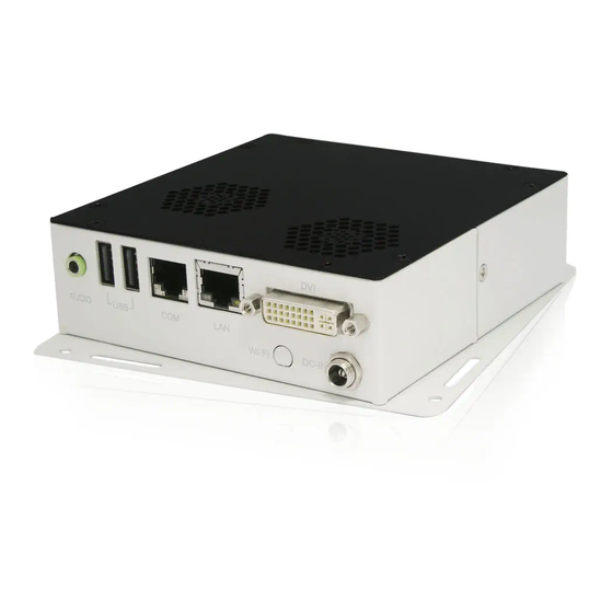
Components I/O View Refer to the diagram below to identify the components on this side of the system. The Digital Visual Interface (DVI) port supports a high quality VGA-compatible device such as a monitor or projector to allow viewing on a larger external display. -
Page 10: Specification
Specification System Mainboard EB-900 Construction SGCC 1.0t Chassis Color Black / White Storage 2.5” 80GB SATA HDD x 1 Mounting Wall mount Dimensions 125.5(W) x 36(H) x 125.5(D)mm (4.94” x 1.41” x 4.94”) Power Supply 60W DC adapter Operating Temperature 0°C ~ 45°C (32°F ~ 113°F) Storage Temperature -20°C ~ 80°C Relative Humidity... -
Page 11: Mounting Si-18 To The Wall
Mounting SI-18 to the Wall You can install SI-18 on plastic (LCD monitor), wood, drywall surface over studs, or a solid concrete or metal plane directly. Ensure the installer uses at least four M3 length 6mm screws to secure the system on wall. Six M3 length 6mm screws are recommended to secure the system on wall. -
Page 12: Selecting The Location
Mounting to hollow walls Method 1: Wood surface – A minimum wood thickness – 38mm (1.5in.) by 25.4 cm (10in.) – of high, construction – grade wood is recommended. Note: This method provides the most reliable attachment of the unit with little risk that the unit will come loose or require ongoing maintenance. -
Page 13: Exploded View Of The Si-18 Assembly
Exploded view of the SI-18 assembly Parts description Part NO. Description Part NO. Description HDD bracket EB900 FAN Set FAN bracket Heatsink FAN Dock Bottom Chassis / Mounting Chassis Body – I/O Chassis Body Top cover... -
Page 14: Installation
Installation Installing WLAN antenna (Optional) SI-18 reserved one SMA connector hole for WLAN (wireless LAN) antenna connection on I/O side. It means you can only use one antenna solution WLAN card. For 802.11n solution, you can only have up to 150Mbit/s performance. You can have WLAN feature by purchase WLAN set from your sales representative. - Page 15 Hold WLAN antenna SMA head carefully and through the hole on I/O wall. Beware the direction of SMA head with the hole, there only has one direction can pass through the antenna hole. And there has one washer shall be put on head before through into the hole, point C.
- Page 16 Install your WLAN card on mini-PCIe connector and use the screw provided by WLAN card to secure WLAN card in position on point D. Wiring the IPX connector on WLAN card and manage your internal antenna...
- Page 17 cable routing. Screw bottom chassis back to system with 8 screws where disassembled by procedure 2 in above.
-
Page 18: Installing The Memory
Installing the memory The motherboard supports two DDR3 memory socket for a maximum total memory of 4GB in DDR3 memory type. Installing and Removing Memory Module (CN1) To install the DDR3 modules, locate the memory slot on the board and perform the following steps: Hold the DDR3 module so that the key of the DDR3 module align with those on the memory slot. -
Page 19: Setting Jumper
Setting Jumper Jumpers are used on the motherboard to select various settings and features according to your needs and applications. Contact your supplier if you have doubts about the best configuration for your needs. The following lists the connectors and their respective functions. -
Page 20: Pin Definition
JP2: LCD Panel Power Selection LCD Panel Power 3.3V JP6: COM1 RS232 +5V/+12V Power Setting Setting Function Pin 1-2 +12V Short/Closed Pin 3-4 Normal Short/Closed Pin 5-6 Short/Closed Pin Definition... -
Page 21: Bios Setup
BIOS Setup This chapter describes the different settings available in the AMI BIOS that comes with the board. BIOS Introduction The BIOS (Basic Input/Output System) installed in your computer system’s ROM supports Intel processors. The BIOS provides critical low-level support for a standard device such as disk drives, serial ports and parallel ports. -
Page 22: Main Bios Setup
Main BIOS Setup This setup allows you to record some basic hardware configurations in your computer system and set the system clock. Note: If the system cannot boot after making and saving system changes with Setup, the AMI BIOS supports an override to the CMOS settings that resets your system to its default. - Page 23 System Time Set the Time. Use Tab to switch between Time elements.
-
Page 24: Advanced Settings
Advanced Settings This section allows you to configure and improve your system and allows you to set up some system features according to your preference. Launch PXE OpROM Enable or Disable Boot Option for Legacy Network Devices. Launch Storage OpROM Enable or Disable Boot Option for Legacy Mass Storage Devices with Option ROM. - Page 25 PCI Subsystem Settings This section allows you to configure the PCI, PCI-X and PCI Express settings. PCIE Configuration The fields under PCIE Configuration features settings for Primary Dual Slot Config, GPP Slots Power Limit, GFX ports, GPPs and NB-SB port features. Internal Graphics Mode The settings for IB828 are Disabled and UMA;...
- Page 26 Memory Hole At 15M-16M In order to improve performance, certain space in memory can be reserved for ISA cards. This memory must be mapped into the memory space below 16 MB. The choices are Enabled and Disabled. System BIOS Cacheable The setting of Enabled allows caching of the system BIOS ROM at F000h-FFFFFh, resulting in better system performance.
- Page 27 Maximum Read Request Launches (Enabled/Disabled) the boot option for legacy network devices. PCI Express Link Settings Set Maximum Read Request Size of PCI Express Device or allow System BIOS to select the value. ASPM Support Set the ASPM Level: Force L0 – Force all links to L0 State AUTO –...
- Page 28 Lock legacy Resources Enabled or Disabled Lock of Legacy Resources S3 Video Repost Enabled or Disabled S3 Video Repost.
- Page 29 CPU Configuration This section shows the CPU configuration parameters. Limit CPUID Maximum Disabled for Windows XP. PSS Support Enabled /disabled the generation of ACPI_PPC, and _PCT objects. PSTATE Adjustment Provide to adjust startup P-state level. PPC adjustment Provide to adjust_PPC object. NX Mode Enabled/disabled NO-execute page protection Function.
- Page 30 C6 Mode Enabled/disabled C6. Node 0 Information View Memory Information related to Node 0.
- Page 31 Auto Power On Schedule This section setups the power on time for the system. Schedule Slot 1 Setup the hou/minute for sytem power on. Schedule Slot 2 Setup the hou/minute for sytem power on. IDE Configuration This section shows the IDE devices configuration. Serial-ATA Controller Enable / Disable Serial ATA Controller.
- Page 32 USB Configuration Legacy USB Support Enables Legacy USB support. AUTO option disables legacy support if no USB devices are connected. DISABLE option will keep USB devices available only for EFI applications. EHCI Hand-off Enabled/Disabled. This is a workaround for Oses without EHCI hand-off support. The EHCI ownership change should be claimed by EHCI driver.
- Page 33 Super IO Configuration Serial Port 0/1 Configuration Set Parameters of Serial Port 0/1 (COMA/COMB) Power Failure The options: Keep last state, By pass mode, Always on, and Always off. H/W Monitor Temperatures/Voltages The values are read-only values as monitored by the system and show the PC health status.
- Page 34 CPU Shutdown Temperature Aside from the Disabled options, this field allows the setting of shutdown temperature from 70C to 95C.
-
Page 35: Chipset Settings
Chipset Settings This section allows you to configure and improve your system and allows you to set up some system features according to your preference. North Bridge This item shows the North Bridge Parameters. North Bridge LVDS Config Select This item shows the Specify INT15 options for LVDS South Bridge This item shows the South Bridge Parameters. - Page 36 North Bridge This section allows you to configure the North Bridge Chipset. IOMMU Mode IOMMU is supported on LINUX based systems to convert 32bit I/O to 64bit MMIO. Memory Clock This option allows user to select different memory clock.
- Page 37 GFX Configuration PSPP Policy PCIe speed power policy. Memory Configuration Integrated Graphics Enable Integrate Graphics controller. Node 0 Information View memory information related to Node 0.
- Page 38 North Bridge LVDS Config Select South Bridge This section allows you to configure the South Bridge Chipset.
- Page 39 SB SATA Configuration OnChip SATA Type Native IDE / n RAID / n AHCI / n AHCI / n Legacy IDE / n IDE->AHCI / n HyperFlash...
- Page 40 SB USB Configuration SB GPP Port Configuration...
-
Page 41: Boot Settings
SB HD Azalia Configuration Boot Settings This section allows you to configure the boot settings according to your preference. Setup Prompt Timeout Number of seconds to wait for setup activation key. 65535(0xFFFF) means indefinite waiting. Bootup NumLock State Select the keyboard NumLock state. -
Page 42: Security Settings
Quiet Boot Enables/Disables Quiet Boot option. GateA20 Active UPON REQUEST – GA20 can be disabled using BIOS services. ALWAYS – do not allow disabling GA20; this option is useful when any RT code is executed above 1MB. Option ROM Messages Set display mode for Option ROM. -
Page 43: Save & Exit Settings
Save & Exit Settings Save Changes and Exit Exit system setup after saving the changes. Disacard Changes and Exit Exit system setup without saving any changes. Save Changes and Reset Reset the system after saving the changes. Discard Changes and Reset Reset system setup without saving any changes. - Page 44 Restore Defaults Restore/Load Defaults values for all the setup options. Save as User Defaults Save the changes done so far as User Defaults. Restore User Defaults Restore the User Defaults to all the setup options. Boot Override Pressing ENTER causes the system to enter the OS. Launch EFI Shell from filesystem device Attempts to launch EFI Shell application (Shellx64.efi) from one of the available filesystem devices.
-
Page 45: Driver Installation
Driver Installation This section describes the installation procedures for software and drivers. The software and drivers are included with the motherboard. If you find the items missing, please contact the vendor where you made the purchase. -
Page 46: Amd A55E Chipset Family Graphic Driver Installation
AMD A55E Chipset Family Graphic Driver Installation Follow the steps below to install the AMD A55E chipset family graphics drivers. 1. Insert the CD that comes with the system. Click AMD, then AMD A55E Chipset Drivers, and then AMD A55E Series Graphics Drivers. - Page 47 2. When the welcome screen to the ATI – Catalyst™ Install Manager appears, click Next. Now, click Install to allow the installation of the software components.
- Page 48 3. Select Express and click Next to proceed with the installation. On the following screen, click Finish to complete the installation process.
- Page 50 Realtek High Definition Audio Driver Installation Follow the steps below to install the Realtek HD audio drivers. 1. Insert the CD that comes with the system. Click AMD and click Realtek High Definition Audio Driver.
- Page 51 2. When the welcome screen to the Audio Driver Setup appears, click Next to start the software installation. Once the InstallShield Wizard is complete, click Finish to restart the computer.
- Page 52 Realtek LAN Controller Drivers Installation Follow the steps below to install the Realtek LAN drivers. 1. Insert the CD that comes with the system. Click Intel, then LAN Card, and then Realtek Lan Controller Drivers.. 2. Click Realtek RTL8111E LAN Drivers.
- Page 53 3. When the Welcome screen of the InstallShield Wizard appears, click Next to continue. 4. When the InstallShieldWizard has finished installing the Realtek LAN drivers, click Finish.
- Page 54 Appendix ~This page is intentionally left blank~...
Need help?
Do you have a question about the SI-18 Series and is the answer not in the manual?
Questions and answers