Table of Contents
Advertisement
Quick Links
Advertisement
Table of Contents

Related Manuals for IBASE Technology SI-626


Summary of Contents for IBASE Technology SI-626
- Page 1 SI-626 Digital Signage Player User’s Manual Version 1.1 (Nov. 2018)
- Page 2 No part of this publication may be reproduced, copied, stored in a retrieval system, translated into any language or transmitted in any form or by any means, electronic, mechanical, photocopying, or otherwise, without the prior written consent of IBASE Technology, Inc. (hereinafter referred to as “IBASE”).
-
Page 3: Compliance
0.1% by weight (1000 ppm) except for cadmium, limited to 0.01% by weight (100 ppm). • Lead (Pb) • Mercury (Hg) • Cadmium (Cd) • Hexavalent chromium (Cr6+) • Polybrominated biphenyls (PBB) • Polybrominated diphenyl ether (PBDE) SI-626 User Manual... -
Page 4: Important Safety Information
CAUTION There is a danger of explosion if the lithium-ion battery is replaced with an incorrect battery. Replace only with the same or equivalent type recommended by the manufacturer. Dispose of used batteries by observing local regulations. SI-626 User Manual... -
Page 5: Warranty Policy
The arrangement of the peripherals • Software used (such as OS and application software) 3. If repair service is required, please download the RMA form at http://www.ibase.com.tw/english/Supports/RMAService/. Fill out the form and contact your distributor or sales representative. SI-626 User Manual... -
Page 6: Table Of Contents
CPU Fan Power Connector (J1, J2, J3) ....... 19 2.4.4 USB 2.0 Ports Header (J7) ........... 19 2.4.5 System Function Connector (J18) ........20 2.4.6 Digital I/O Connector (J17) ........... 20 2.4.7 Battery Connector (JBAT1) ..........21 SI-626 User Manual... - Page 7 AMD Eyefinity Multiple Displays Configuration ........48 Setting Up AMD Eyefinity Using Quick Setup ......48 Customizing AMD Eyefinity Using Try Advanced Setup ..52 Video Wall Layouts Applicable to SI-626 ........ 58 I/O Port Address Map ................60 Interrupt Request Lines (IRQ) ............... 63 Watchdog Timer Configuration ..............
-
Page 8: Chapter 1 General Information
Chapter 1 General Information The information provided in this chapter includes: • Features • Packing List • Specifications • Optional Accessories • Overview • Dimensions... -
Page 9: Introduction
1.1 Introduction ® The SI-626 is powered by Intel Generation mobile processors. It supports three display outputs for HDMI high definition video playback and iSmart energy-saving features such as power on/off scheduling and power resume function. The device operates in environments with temperatures ranging from 0°C to 45°C. -
Page 10: Packing List
General Information 1.3 Packing List If you buy a barebone SI-626, your product package should include the items listed below. If any of the items below is missing, contact the distributor or the dealer from whom you have purchased the product. -
Page 11: Specifications
6 x HDMI 1.4 with hardware EDID emulation 2 x GbE RJ45 LAN port • Serial 2 x RJ50 for RS-232 serial port 4 x USB 3.0 • 1 x Line-Out Audio Jack • 1 x Mic-In Power Jack 1 x DC-In power jack SI-626 User Manual... - Page 12 Note: The product performance relies on the system functioning as a whole. The level of CPU/APU/GPU processor, the interaction among the processor and the memory and storage bandwidth, or the functionality of the digital signage application software may affect the product performance. SI-626 User Manual...
-
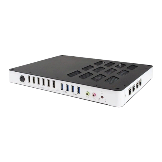
Page 13: I/O View
(From left to right: Line-Out, Mic-In) LED Indicator for HDD Be sure to press the EDID Button to acquire or change the EDID data when the connected display/monitor cannot be recognized, or the displayed image does not fit the screen. SI-626 User Manual... -
Page 14: Dimensions
General Information 1.7 Dimensions Unit: mm SI-626 User Manual... -
Page 15: Hardware Installation & Motherboard Information
Chapter 2 Hardware Installation & Motherboard Information This section contains general information about: • Installations • Jumper and connectors... -
Page 16: Installations
To remove a module, use your fingers to press the clips outwards until the module pops up. Grab the module gently and pull it out of the slot. SI-626 User Manual... -
Page 17: Mini-Pcie & M.2 Cards Installation
1. Fasten the hex nut and the washer. Then 2. Apply adhesive around here. install the antenna. Info: The diameter of the nut is around 6.35 mm (0.25”-36UNC). SI-626 User Manual... -
Page 18: Hdmi Cable Holder Installation
HDMI cables, you can use the holder to prevent the cables from coming loose. Align the holder to the HDMI ports and secure it with the supplied two round-head screws with washer as shown below. SI-626 User Manual... -
Page 19: Mounting Installation
The device with the optional mounting plate is shown as the figure below. Prepare at least 4 screws (M3) to install the device on the wall. • VESA 75 x 75 mm • VESA 100 x 100mm • Wall Mount / TV Mount: 200 x 100 mm SI-626 User Manual... -
Page 20: Pin Assignment For Power Input Connector
Pin Assignment for Power Input Connector Signal Signal Ground +12V Ground +12V 2.1.7 Pin Assignment for COM1 & COM2 Serial Ports (RJ50 connector) ➔ COM1 RS-232/422/485 port: Signal Name RS-232 RS-422 RS-485 Ground Ground Ground Ground Ground Ground DATA+ DATA- SI-626 User Manual... - Page 21 COM2 RS-232 port: Signal Name Signal Name DSR (Data set ready) DCD (Data carrier detect) Ground DTR (Data terminal ready) Ground CTS (Clear to send) TX (Transmit) RTS (Request to send) RX (Receive) RI (Ring indicator) SI-626 User Manual...
-
Page 22: Setting The Jumpers
1 2 3 When two pins of a jumper are encased in a jumper cap, this jumper is closed, i.e. turned On. When a jumper cap is removed from two jumper pins, this jumper is open, i.e. turned Off. SI-626 User Manual... -
Page 23: Jumper & Connector Locations On Motherboard
2.3 Jumper & Connector Locations on Motherboard Motherboard: MBD626 SI-626 User Manual... -
Page 24: 22Jumper & Connectors Quick Reference
Be sure to press the EDID Button to acquire or change the EDID data when the connected display/monitor cannot be recognized, or the displayed image does not fit the screen. [1]: Refer to the section 2.1.7 Pin Assignment for COM1 & COM2 Serial Ports for the pin assignments. SI-626 User Manual... -
Page 25: Clearing Cmos Data (Jp2)
2.4.1 Clearing CMOS Data (JP2) Function Pin closed Illustration Normal (default) Clear CMOS 2.4.2 DC Power Input (CN17) Signal Signal Ground +12V Ground +12V SI-626 User Manual... -
Page 26: Cpu Fan Power Connector (J1, J2, J3)
Motherboard Information 2.4.3 CPU Fan Power Connector (J1, J2, J3) Signal Name Signal Name Ground Rotation detection +12V 2.4.4 USB 2.0 Ports Header (J7) Signal Name Signal Name Data- Data- Data+ Data+ Ground Ground SI-626 User Manual... -
Page 27: System Function Connector (J18)
2.4.5 System Function Connector (J18) Signal Name Signal Name Power BTN Power BTN HDD LED+ HDD LED- Reset BTN Reset BTN +5VSB 2.4.6 Digital I/O Connector (J17) Signal Name Signal Name Ground OUT3 OUT1 OUT2 OUT0 SI-626 User Manual... -
Page 28: Battery Connector (Jbat1)
Motherboard Information 2.4.7 Battery Connector (JBAT1) JBAT1 Signal Name Signal Name Battery+ Ground SI-626 User Manual... -
Page 29: Chapter 3 Driver Installation
Chapter 3 Driver Installation The information provided in this chapter includes: • ® Intel Chipset Software Installation Utility • HD Audio Driver Installation • LAN Driver Installation • ® Intel Management Engine Driver Installation • USB 3.1 Driver Installation... -
Page 30: Introduction
INF files for Plug & Play function for the chipset components. Follow the instructions below to complete the installation. 1. Run the Setup.exe file. ® 2. When the Welcome screen to the Intel Chipset Device Software appears, click Next to continue. SI-626 User Manual... - Page 31 3. Accept the license agreement and proceed with the installation process. 4. On the Readme File Information screen, click Install. 5. Installation is now complete. Restart the system for changes to take effect. SI-626 User Manual...
-
Page 32: Intel ® Graphics Driver Installation
Driver Installation ® 3.3 Intel Graphics Driver Installation 1. Run the Setup.exe file. 2. When the Welcome screen appears, click Next to continue. 3. Click Yes to agree with the license agreement and continue the installation. SI-626 User Manual... - Page 33 4. On the Readme File Information and Setup Progress screen, click Next. 5. Choose a destination folder for installation. 6. Installation is now complete. Restart the system for changes to take effect. SI-626 User Manual...
-
Page 34: Hd Audio Driver Installation
1. Run the Setup.exe file and the wizard starts. 2. On the Welcome screen of the InstallShield Wizard, click Next to start installing the audio driver on your system. 3. Installation is now complete. Restart the system for changes to take effect. SI-626 User Manual... -
Page 35: Lan Driver Installation
4. On the Setup Options screen, tick the checkbox to select the desired driver(s) and click Next. 5. When the wizard is ready for installation, click Install. 6. Installation is now complete. Restart the system for changes to take effect. SI-626 User Manual... -
Page 36: Intel Management Engine Components Drivers Installation
Installation 1. Run the Setup.exe file. 2. When the Welcome screen appears, click Next. 3. Accept the license agreement and click Next for installation. 4. Installation is now complete. Restart the system for changes to take effect. SI-626 User Manual... -
Page 37: Chapter 4 Bios Setup
Chapter 4 BIOS Setup This chapter describes the different settings available in the AMI BIOS that comes with the board. The topics covered in this chapter are as follows: • Main Settings • Advanced Settings • Chipset Settings • Security Settings •... -
Page 38: Introduction
These defaults have been carefully chosen by both AMI and your system manufacturer to provide the absolute maximum performance and reliability. Changing the defaults could make the system unstable and crash in some cases. SI-626 User Manual... -
Page 39: Main Settings
Set the time. Use the <Tab> key to switch between the data elements. 4.4 Advanced Settings This section allows you to configure, improve your system and allows you to set up some system features according to your preference. SI-626 User Manual... -
Page 40: Cpu Configuration
Number of cores to enable in each processor package. Enables / Disables AES (Advanced Encryption Standard). Intel Trusted Execution Enables utilization of additional hardware Technology capabilities provided by Intel(R) Trusted Execution Technology. Changes require a full power cycle to take effect. SI-626 User Manual... -
Page 41: Power & Performance
Technology support. Enabling will expose the CPPC v2 interface to allows for hardware controlled P-states. Turbo Mode Enables / Disables processor Turbo Mode (requires EMTTM enabled too). Auto means enabled unless max. turbo ratio is bigger than 16 – SKL A0 W/A. SI-626 User Manual... -
Page 42: Pch-Fw Configuration
(OS/S4 Sleep State). This option may not be effective with some operating systems. ACPI Sleep State Select the highest ACPI sleep state the system will enter when the Suspend button is pressed. Lock Legacy Resources Enables / Disables Lock of Legacy Resources. SI-626 User Manual... -
Page 43: Ismart Controller
For example, if setting up a schedule from Wednesday 5 p.m. to Thursday 2 a.m., configure two schedule slots. But if setting up a schedule from 3 p.m to 5 p.m. on Wednesday, configure only a schedule slot. SI-626 User Manual... -
Page 44: F81846 Super Io Configuration
BIOS Setup 4.4.6 F81846 Super IO Configuration BIOS Setting Description Serial Port Configuration Sets parameters of Serial Ports (COMA). Enables / Disables the serial port and select an optimal setting for the Super IO device. SI-626 User Manual... -
Page 45: Hardware Monitor
This field enables or disables the Shutdown Temperature Temperature Temperatures / Voltages These fields are the parameters of the hardware monitoring function feature of the motherboard. The values are read-only values as monitored by the system and show the PC health status. SI-626 User Manual... -
Page 46: Network Stack Configuration
If disabled, Ipv4 HTTP boot option will not be created. PXE boot wait time Assigns a period of time to press ESC key to abort the PXE boot. Media detect count Assigns a number of times to check the presence of media. SI-626 User Manual... -
Page 47: Csm Configuration
Option ROM. • Immediate executes the trap right away • Postponed executes the trap during legacy boot. Boot option filter Controls the priority of Legacy and UEFI. Network Controls the execution of UEFI and Legacy PXE OpROM. SI-626 User Manual... -
Page 48: Nvme Configuration
BIOS Setup 4.4.10 NVMe Configuration SI-626 User Manual... -
Page 49: Chipset Settings
4.5 Chipset Settings BIOS Setting Description System Agent (SA) System Agent parameters Configuration PCH-IO Configuration PCH parameters 4.5.1 System Agent Configuration SI-626 User Manual... -
Page 50: Pch-Io Configuration
BIOS Setup 4.5.2 PCH-IO Configuration BIOS Setting Description SATA and RST SATA device options settings Configuration 4.5.2.1. SATA and RST Configuration BIOS Setting Description SATA Controller(s) Enables / Disables the SATA device. SI-626 User Manual... -
Page 51: Security Settings
4.6 Security Settings BIOS Setting Description Administrator Password Sets an administrator password for the setup utility. User Password Sets a user password. SI-626 User Manual... -
Page 52: Boot Settings
There no effect for BBS boot options. Boot Mode Select Selects a Boot mode. Boot Option Priorities Sets the system boot order priorities for hard disk, CD/DVD, USB, Network. SI-626 User Manual... -
Page 53: Save & Exit Settings
Restore Defaults Restores / Loads defaults values for all the setup options. Save as User Defaults Saves the changes done so far as user defaults. Restore User Defaults Restores the user defaults to all the setup options. SI-626 User Manual... -
Page 54: Appendix
Appendix This section provides the mapping addresses of peripheral devices and the sample code of watchdog timer configuration. • AMD Eyefinity Multiple Displays • I/O Port Address Map • Interrupt Request Lines (IRQ) • Watchdog Timer Configuration... -
Page 55: Amd Eyefinity Multiple Displays Configuration
Eyefinity Display Group. So, arrange the displays in a 3x1 configuration in extended desktop before configuring AMD Eyefinity with Quick Setup. To set up AMD Eyefinity with Quick Setup: 1. Open AMD Radeon Settings: Right-click on the desktop and select AMD Radeon Settings. SI-626 User Manual... - Page 56 However, this feature is not supported. Do not confuse with Try Advanced Setup (see below picture), which becomes available after Eyefinity Quick Setup is complete. The Try Advanced Setup option is used to customize the Eyefinity Display Group created after Eyefinity Quick Setup is complete. SI-626 User Manual...
- Page 57 Eyefinity Display Group. Refer to A.2 Customizing AMD Eyefinity Using Try Advanced Setup for details. Arrange Displays after Eyefinity Quick Setup To arrange displays in desired positions (optional): 1. Click Arrange Displays after Eyefinity Quick Setup is complete. SI-626 User Manual...
- Page 58 (i.e. Eyefinity Display Group + Extended Desktop Displays). In this example, physically connect 3 of the 4 displays first and arrange them in 3 x 1 extended desktop in the Operating System’s display settings. SI-626 User Manual...
-
Page 59: Customizing Amd Eyefinity Using Try Advanced Setup
Eyefinity Display Group or in one preferred display. By default, the Taskbar extends across all displays in a single row AMD Eyefinity Display Group. In a multi-row AMD Eyefinity Display Group, it extends across the bottom row of displays. SI-626 User Manual... - Page 60 4. To move the Taskbar, simply drag and drop it to the desired display. Ensure that the Taskbar setting is not set to “locked”. 5. To have the Taskbar running across multiple displays again, uncheck the Position the Windows taskbar on a single display option and click Continue. SI-626 User Manual...
- Page 61 Desktop option changes how the desktop image is shown across the displays by resizing it. To resize the desktop: 1. Click Try Advanced Setup (under Eyefinity tab in AMD Radeon Settings) after Eyefinity Quick Setup is complete. 2. Click Resize Desktop once Radeon Additional Settings launches. SI-626 User Manual...
- Page 62 Eyefinity Quick Setup is complete. 2. Click Adjust Bezel Compensation once Radeon Additional Settings launches. 3. Use the Chevrons (arrow heads) to move the triangle test pattern until it is properly aligned (as shown in below picture). SI-626 User Manual...
- Page 63 To customize Eyefinity desktop resolution: 1. Click Try Advanced Setup (under Eyefinity tab in AMD Radeon Settings) after Eyefinity Quick Setup is complete. 2. Click Customize Eyefinity Desktop Resolution once Radeon Additional Settings launches. SI-626 User Manual...
- Page 64 4. Select the preferred resolution from the Custom Resolution drop-down menu, and click Apply to save the setting. Open the Operating System’s display settings menu to change the resolution to the Custom Resolution selected in Step #4. SI-626 User Manual...
-
Page 65: Video Wall Layouts Applicable To Si-626
Video Wall Layouts Applicable to SI-626 Configure the matrix grid layouts of video walls with AMD Eyefinity per the following display arrangement. For 3 displays output: • 3 x 1 Landscape Display Group • 3 x 1 Portrait Display Group •... - Page 66 • 5 x 1 Landscape Display Group • 5 x 1 Portrait Display Group • 1 x 5 Landscape Display Group For 6 displays output: • 3 x 2 Landscape Display Group • 2 x 3 Landscape Display Group SI-626 User Manual...
-
Page 67: I/O Port Address Map
Realtek PCIe GBE Family Controller #2 0x0000D000-0x0000D0FF Intel(R) 100 Series/C230 Series Chipset Family PCI Express Root Port #4 - A113 0x0000E000-0x0000EFFF Intel(R) Xeon(R) E3 - 1200/1500 v5/6th Gen Intel(R) Core(TM) PCIe Controller (x16) - 1901 0x0000E000-0x0000EFFF AMD Radeon E8860 SI-626 User Manual... - Page 68 Programmable interrupt controller 0x000003F8-0x000003FF Communications Port (COM1) 0x000002F8-0x000002FF Communications Port (COM2) 0x000003E8-0x000003EF Communications Port (COM3) 0x00001854-0x00001857 Motherboard resources 0x0000C000-0x0000C0FF Realtek PCIe GBE Family Controller 0x0000C000-0x0000C0FF Intel(R) 100 Series/C230 Series Chipset Family PCI Express Root Port #5 - A114 SI-626 User Manual...
- Page 69 Intel(R) 100 Series/C230 Series Chipset Family SMBus - A123 0x00000060-0x00000060 Standard PS/2 Keyboard 0x00000064-0x00000064 Standard PS/2 Keyboard 0x00000040-0x00000043 System timer 0x00000050-0x00000053 System timer 0x0000F050-0x0000F057 Standard SATA AHCI Controller 0x0000F040-0x0000F043 Standard SATA AHCI Controller 0x0000F020-0x0000F03F Standard SATA AHCI Controller SI-626 User Manual...
-
Page 70: Interrupt Request Lines (Irq)
Microsoft PS/2 Mouse IRQ 0 System timer IRQ 16 High Definition Audio Controller IRQ 4294967291 Standard SATA AHCI Controller IRQ 4294967293 Intel(R) 100 Series/C230 Series Chipset Family PCI Express Root Port #4 - A113 IRQ 4294967290 AMD Radeon E8860 SI-626 User Manual... -
Page 71: Watchdog Timer Configuration
Fintek 81846, program abort.\n"); return(1); }//if (SIO == 0) if (argc != 2) printf(" Parameter incorrect!!\n"); return (1); bTime = strtol (argv[1], endptr, 10); printf("System will reset after %d seconds\n", bTime); if (bTime) EnableWDT(bTime); } else DisableWDT(); } return 0; SI-626 User Manual... - Page 72 //--------------------------------------------------------------------------- void DisableWDT(void) unsigned char bBuf; Set_F81846_LD(0x07); //switch to logic device 7 bBuf = Get_F81846_Reg(0xFA); bBuf &= ~0x01; Set_F81846_Reg(0xFA, bBuf); //disable WDTO output bBuf = Get_F81846_Reg(0xF5); bBuf &= ~0x20; bBuf |= 0x40; Set_F81846_Reg(0xF5, bBuf); //disable WDT //--------------------------------------------------------------------------- SI-626 User Manual...
- Page 73 Init_Finish; } F81846_BASE = 0x00; result = F81846_BASE; Init_Finish: return (result); //--------------------------------------------------------------------------- void Unlock_F81846 (void) outportb(F81846_INDEX_PORT, F81846_UNLOCK); outportb(F81846_INDEX_PORT, F81846_UNLOCK); //--------------------------------------------------------------------------- void Lock_F81846 (void) outportb(F81846_INDEX_PORT, F81846_LOCK); //--------------------------------------------------------------------------- void Set_F81846_LD( unsigned char LD) Unlock_F81846(); outportb(F81846_INDEX_PORT, F81846_REG_LD); outportb(F81846_DATA_PORT, LD); Lock_F81846(); SI-626 User Manual...
- Page 74 //--------------------------------------------------------------------------- #defineF81846_INDEX_PORT (F81846_BASE) #defineF81846_DATA_PORT (F81846_BASE+1) //--------------------------------------------------------------------------- #defineF81846_REG_LD 0x07 //--------------------------------------------------------------------------- #define F81846_UNLOCK 0x87 #defineF81846_LOCK 0xAA //--------------------------------------------------------------------------- unsigned int Init_F81846(void); void Set_F81846_LD( unsigned char); void Set_F81846_Reg( unsigned char, unsigned char); unsigned char Get_F81846_Reg( unsigned char); //--------------------------------------------------------------------------- #endif // F81846_H SI-626 User Manual...
Need help?
Do you have a question about the SI-626 and is the answer not in the manual?
Questions and answers