
Related Manuals for IBASE Technology SW-101-N


Summary of Contents for IBASE Technology SW-101-N
- Page 1 SW-101-N Outdoor Waterproof Digital Signage Player User’s Manual Version 1.0 (Apr. 2019)
- Page 2 No part of this publication may be reproduced, copied, stored in a retrieval system, translated into any language or transmitted in any form or by any means, electronic, mechanical, photocopying, or otherwise, without the prior written consent of IBASE Technology, Inc. (hereinafter referred to as “IBASE”).
-
Page 3: Compliance
Compliance In a domestic environment, this product may cause radio interference in which case users may be required to take adequate measures. This product has been tested and found to comply with the limits for a Class B device, pursuant to Part 15 of the FCC Rules. These limits are designed to provide reasonable protection against harmful interference in a residential installation. -
Page 4: Important Safety Information
Important Safety Information Carefully read the precautions before using the device. Environmental conditions: • Lay the device horizontally on a stable and solid surface in case the device may fall, causing serious damage. • Leave plenty of space around the device and do not block the openings for ventilation. -
Page 5: Caution
CAUTION There is danger of explosion if internal lithium-ion battery is replaced by an incorrect type. Replace only with the same or equivalent type recommended by the manufacturer. Dispose of used batteries according to the manufacturer’s instructions. Warranty Policy • IBASE standard products: 24-month (2-year) warranty from the date of shipment. -
Page 6: Table Of Contents
Table of Contents Compliance....................iii Important Safety Information ............... iv WARNING ...................... iv CAUTION ......................v Warranty Policy ....................v Technical Support & Services ..............v Chapter 1 General Information ..............1 Introduction ..................... 2 Features ....................2 Packing List .................... 3 Optional Accessories ................ - Page 7 2.8.5 Speaker Connector (J9, J10) ..........20 2.8.6 COM RS-232 Connector (J11, J12) ........20 2.8.7 LAN Connector (J13) ............21 2.8.8 HDMI Connector (J14, J15) ..........21 2.8.9 Digital I/O Connector (J16) ........... 22 2.8.10 System Fan Power Connector (SYS_FAN1) ......22 Chapter 3 Driver Installation ..............
-
Page 8: Chapter 1 General Information
Chapter 1 General Information The information provided in this chapter includes: • Features • Packing List • Accessories • Specifications • Overview • Dimensions... -
Page 9: Introduction
1.1 Introduction The SW-101-N is a waterproof digital signage player designed for both indoor and harsh outdoor environments. This rugged fanless signage player is integrated with a 1.91GHz Intel® Atom™ Processor E3845 Quad-Core Processor and Intel® HD graphics (Gen 7-LP) 4EU. -
Page 10: Packing List
• SW-101-N Digital Signage Player 1.4 Optional Accessories IBASE provides optional accessories as follows. Please contact us or your dealer if you need any. - Page 11 Storage 1 x mSATA slot Power DC-In 12V Requirement Power Supply 84W power adapter (Optional) Watchdog Timer 256 segments, 0, 1, 2…255 sec/min Watchdog Chassis Aluminum die-casting and heavy-duty steel, black Mounting Wall mount Dimensions 227 x 70x 192 mm (8.93” x 2.75” x 7.55”) (W x H x D) Net Weight 2.8 kg (6.17 lb)
-
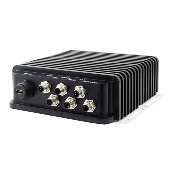
Page 12: Overview
General Information 1.6 Overview Front View No. Name Name Antenna Holes Wall Mounting Kit Rear View No. Name Name Digital I/O Port HDMI Port (C3) (M12 to open wire) USB 2.0 Ports (M12) GbE LAN Port (M12) DC Power Input (M12 to 3-pin COM RS-232 Port (M12) terminal block) SI-614 / SI-614-M User Manual... -
Page 13: Dimensions
Oblique View 1.7 Dimensions Unit: mm SI-614 / SI-614-M User Manual... -
Page 14: Hardware Installation & Motherboard Information
Chapter 2 Hardware Installation & Motherboard Information The information provided in this chapter includes: • Installation or replacement • Information and locations of connectors... -
Page 15: Installation / Replacement
2.1 Installation / Replacement Before any installation or any card/module replacement, remove the following 12 screws to take away the bottom chassis first. 2.1.1 Memory To install the modules, locate the memory slot on the motherboard and perform the following steps: 1. -
Page 16: Mini-Pcie Cards
Hardware Configuration 2.1.2 Mini-PCIe Cards 1. Locate the mini-PCIe or M.2 slot inside the device. 2. Align the key of the mini-PCIe card to the mini-PCIe interface, and insert the card slantwise. (Insert the M.2 card in the same way.) 3. -
Page 17: Mounting Installation
2.1.4 Mounting Installation Requirements Before mounting the system, ensure that you have enough room for the power adaptor and signal cable routing, and have good ventilation for the power adaptor. The method of mounting must be able to support weight of the SI- 61S plus the weight of the suspending cables attached to the system. -
Page 18: Pinout For Dc Power Input Connector
Hardware Configuration 2.2 Pinout for DC Power Input Connector DC Power Input Cable: M12 to 3-pin terminal block DC power input cable is optional for purchase. M12 end: Signal Name Signal Name Voltage+ Voltage- Ground Terminal block end: Signal Name Signal Name Voltage- (Black) Ground (Green) -
Page 19: Pinout For Digital I/O Connector
2.3 Pinout for Digital I/O Connector Digital I/O Cable: M12 to open wire Digital I/O cable is optional for purchase. M12 end Open Wire end Signal Name Ground Ground Ground User self-defined Ground Ground OUT1 Ground SI-614 / SI-614-M User Manual... -
Page 20: Pinout For Com1 Rs-232 Port
Hardware Configuration 2.4 Pinout for COM1 RS-232 Port Seral Cable: M12 to D-Sub9 Serial cable is optional for purchase. M12 end D-Sub-end Signal Name Ground SI-614 / SI-614-M User Manual... -
Page 21: Setting The Jumpers
2.5 Setting the Jumpers Set up and configure your SI-613 by using jumpers for various settings and features according to your needs and applications. Contact your supplier if you have doubts about the best configuration for your use. 2.5.1 How to Set Jumpers Jumpers are short-length conductors consisting of several metal pins with a non-conductive base mounted on the circuit board. -
Page 22: Jumper & Connector Locations On Motherboard
Hardware Configuration 2.6 Jumper & Connector Locations on Motherboard Motherboard: SGT-MB2 SGT-MB2 – top and I/O SI-614 / SI-614-M User Manual... -
Page 23: Jumpers Quick Reference
2.7 Jumpers Quick Reference Function Connector Name Page Clearing CMOS Data Clearing ME Register Factory Use Only JP1, JP2, JP3 2.7.1 Clearing CMOS Data (JP4) Function Pin closed Illustration Normal (default) Clear CMOS SI-614 / SI-614-M User Manual... -
Page 24: Clearing Me Register (Jp5)
Hardware Configuration 2.7.2 Clearing ME Register (JP5) Function Pin closed Illustration Normal (default) Clear ME SI-614 / SI-614-M User Manual... -
Page 25: Connectors Quick Reference
2.8 Connectors Quick Reference Function Connector Name Page Board Input Power Connector 5V Power Connector RTC Battery Connector Reset Connector Speaker Connector J9 (left), J10 (right) COM RS-232 Connector J11, J12 LAN Connector HDMI Connector J14, J15 Digital I/O Connector System Fan Power Connector SYS_FAN1 Power Button... -
Page 26: Power Connector (J1)
Hardware Configuration 2.8.2 5V Power Connector (J1) Signal Name Signal Name Ground 2.8.3 RTC Battery Connector (J3) Signal Name Signal Name Battery+ Ground 2.8.4 Reset Connector (J8) Signal Name Signal Name Reset Ground SI-614 / SI-614-M User Manual... -
Page 27: Speaker Connector (J9, J10)
2.8.5 Speaker Connector (J9, J10) J9 (Speaker left) J10 (Speaker right) J9: Speaker left Signal Name Signal Name SPK-L+ SPK-L- J10: Speaker right Signal Name Signal Name SPK-R+ SPK-R- 2.8.6 COM RS-232 Connector (J11, J12) Signal Name Signal Name SOUT Ground SI-614 / SI-614-M User Manual... -
Page 28: Lan Connector (J13)
Hardware Configuration 2.8.7 LAN Connector (J13) Signal Name Signal Name MDI3+ MDI3- MDI2+ MDI2- MDI1+ MDI1- MDI0+ MDI0- 2.8.8 HDMI Connector (J14, J15) Signal Name Signal Name TMDS_DATA2_P TMDS_DATA2_N Ground Ground TMDS_DATA1_P TMDS_DATA1_N Ground Ground TMDS_DATA0_P TMDS_DATA0_N Ground Ground TMDS_CLK_P TMDS_CLK_N Ground Ground... -
Page 29: Digital I/O Connector (J16)
2.8.9 Digital I/O Connector (J16) Signal Name Signal Name Ground Ground Ground Ground Ground Ground Ground OUT1 Ground 2.8.10 System Fan Power Connector (SYS_FAN1) Signal Name Signal Name Ground +12V SI-614 / SI-614-M User Manual... -
Page 30: Chapter 3 Driver Installation
Chapter 3 Driver Installation The information provided in this chapter includes: • ® Intel Chipset Software Installation Utility • Graphics Driver • HD Audio Driver • ® Intel Trusted Execution Engine • LAN Driver... -
Page 31: Introduction
3.1 Introduction This section describes the installation procedures for software drivers. The software drivers are available on IBASE website www.ibase.com.tw. Register as a member of our website to download all the necessary drivers and extract for installation. Note: After installing your Windows operating system, you must install the ®... - Page 32 Driver Installation 3. Accept the license agreement and proceed with the installation process. 4. Click Install 5. When the driver is completely installed, restart the computer for changes to take effect. SI-614 / SI-614-M User Manual...
-
Page 33: Graphics Driver Installation
3.3 Graphics Driver Installation 1. Run the Setup.exe file. 2. On the Welcome screen, click Next. 3. Accept the license agreement and click Yes to continue. 4. On the Readme File Information, click Next. SI-614 / SI-614-M User Manual... -
Page 34: Hd Audio Driver Installation
Driver Installation 5. Click Next until the installation starts. 6. When the driver is completely installed, restart the computer for changes to take effect. 3.4 HD Audio Driver Installation 1. Run the Setup.exe file. 2. On the Welcome screen of the InstallShield Wizard, click Next. 3. -
Page 35: Lan Driver Installation
3.5 LAN Driver Installation 1. Run the Setup.exe file. 2. On the Welcome screen of the InstallShield Wizard, click Next. 3. Click Install. 4. When the driver is completely installed, restart the computer for changes to take effect. SI-614 / SI-614-M User Manual... -
Page 36: Intel Trusted Execution Engine Drivers Installation
Driver Installation ® 3.6 Intel Trusted Execution Engine Drivers Installation 1. Run the Setup.exe file. 2. When the Welcome screen appears, click Next. 3. Accept the license agreement and click Next for installation. 4. Click Next until the installation starts. 5. -
Page 37: Chapter 4 Bios Setup
Chapter 4 BIOS Setup This chapter describes the different settings available in the AMI BIOS that comes with the board. The topics covered in this chapter are as follows: • Main Settings • Advanced Settings • Chipset Settings • Security Settings •... -
Page 38: Introduction
BIOS Setup 4.1 Introduction The BIOS (Basic Input/Output System) installed in the ROM of your computer system supports Intel® processors. The BIOS provides critical low-level support for standard devices such as disk drives, serial ports and parallel ports. It also provides password protection as well as special support for detailed fine-tuning of the chipset controlling the entire system. -
Page 39: Main Settings
4.3 Main Settings BIOS Setting Description System Date Sets the date. Use the <Tab> key to switch between the data elements. System Time Set the time. Use the <Tab> key to switch between the data elements. SI-614 / SI-614-M User Manual... -
Page 40: Advanced Settings
BIOS Setup 4.4 Advanced Settings This section allows you to configure, improve your system and allows you to set up some system features according to your preference. BIOS Setting Description OnBoard LAN PXE Rom Controls the execution of UEFI and Legacy PXE OpROM. -
Page 41: Acpi Settings
4.4.1 ACPI Settings BIOS Setting Description Enable ACPI Auto Enables / Disables BIOS ACPI Auto Configuration configuration. Enable Hibernation Enables / Disables system ability to hibernate (OS/S4 Sleep State). This option may not be effective with some operating systems. ACPI Sleep State Selects the highest ACPI sleep state the system will enter when the SUSPEND button is pressed. -
Page 42: Ismart Controller
BIOS Setup 4.4.2 iSmart Controller BIOS Setting Description Power-On after Power Enables / Disables the system to be turned on failure automatically after a power failure. PWR Resume Delay Enables / Disables power on resume delay. Temperature Guardian Generates the reset signal when system hands up on POST. -
Page 43: Super Io Configuration
4.4.3 Super IO Configuration BIOS Setting Description Watchdog Control Controls the Watchdog. Options: Disabled, 30 sec, 60 sec, 90 sec, 120 sec Serial Port 1 & 2 Sets parameters of Serial Port 1 & 2 (COMA Configuration & COMB). Enables / Disables the serial port and select an optimal setting for the Super IO device. - Page 44 BIOS Setup 4.4.3.1. Serial Port 1 Configuration BIOS Setting Description Serial Port Enables / Disables serial port (COM). Change Settings Selects an optimal settings for Super I/O device. Options: • Auto • IO = 3F8h; IRQ = 4 • IO = 3F8h; IRQ = 3, 4, 5, 6, 7, 9, 10, 11, 12 •...
- Page 45 4.4.3.2. Serial Port 2 Configuration BIOS Setting Description Serial Port Enables / Disables serial port (COM). Change Settings Selects an optimal settings for Super I/O device. Options: • Auto • IO = 3E8h; IRQ = 3 • IO = 3E8h; IRQ = 3, 4, 5, 6, 7, 9, 10, 11, 12 •...
-
Page 46: Hw Monitor
BIOS Setup 4.4.4 HW Monitor BIOS Setting Description CPU Shutdown Disables or sets system shutdown temperature Temperature to 70°C, 75°C, 80°C, 85°C, 90°C or 95°C. Temperatures / Voltages These fields are the parameters of the hardware monitoring function feature of the motherboard. -
Page 47: Cpu Configuration
4.4.5 CPU Configuration BIOS Setting Description Socket 0 CPU Information Socket specific CPU Information 4.4.6 PPM Configuration BIOS Setting Description EIST Enables / Disables Intel SpeedStep. SI-614 / SI-614-M User Manual... -
Page 48: Ide Configuration
BIOS Setup 4.4.7 IDE Configuration BIOS Setting Description Serial ATA (SATA) Enables / Disables Serial ATA. SATA Speed Selects SATA speed support as Gen.1 or Gen. Support SATA Mode Selects the SATA mode as IDE or AHCI. Serial ATA Port 1 Enables / Disables Serial ATA Port 1. -
Page 49: Usb Configuration
4.4.8 USB Configuration BIOS Setting Description • Legacy USB Support Enable: Enables Ledacy USB Support. • Auto: Disables legacy support if no USB devices are connected. • Disable: Keeps USB devices available only for EFI applications. XHCI Hand-off This is a workaround for OSes without XHCI hand-off support. -
Page 50: Chipset Settings
BIOS Setup 4.5 Chipset Settings BIOS Setting Description North Bridge Displays the parameters of North Bridge. SI-614 / SI-614-M User Manual... -
Page 51: Security Settings
4.6 Security Settings BIOS Setting Description Administrator Password Sets an administrator password for the setup utility. User Password Sets a user password. SI-614 / SI-614-M User Manual... -
Page 52: Boot Settings
BIOS Setup 4.7 Boot Settings BIOS Setting Description Setup Prompt Timeout Number of seconds to wait for setup activation key. 65535 (0xFFFF) means indefinite waiting. Bootup NumLock State Turns on/off the keyboard NumLock state. Quiet Boot Enables / Disables Quiet Boot option. Fast Boot Enables / Disables boot with initialization of a minimal set of devices required to launch active... -
Page 53: Save & Exit Settings
4.8 Save & Exit Settings BIOS Setting Description Save Changes and Exit Exits system setup after saving the changes. Discard Changes and Exits system setup without saving any changes. Exit Save Changes and Reset Resets the system after saving the changes. Discard Changes and Resets system setup without saving any Reset... -
Page 54: Appendix
Appendix This section provides the mapping addresses of peripheral devices and the sample code of watchdog timer configuration. • I/O Port Address Map • Interrupt Request Lines (IRQ) • Watchdog Timer Configuration... -
Page 55: I/O Port Address Map
A. I/O Port Address Map Each peripheral device in the system is assigned a set of I/O port addresses which also becomes the identity of the device. The following table lists the I/O port addresses used. Address Device Description 0x00000A00-0x00000A0F Motherboard resources 0x00000290-0x0000029F Motherboard resources... - Page 56 Appendix Address Device Description 0x0000E040-0x0000E043 Standard SATA AHCI Controller 0x0000E020-0x0000E03F Standard SATA AHCI Controller 0x000003F8-0x000003FF Communications Port (COM1) 0x000003E8-0x000003EF Communications Port (COM2) 0x00000040-0x00000043 System timer 0x00000050-0x00000053 System timer 0x00000000-0x0000006F PCI Express Root Complex 0x00000078-0x00000CF7 PCI Express Root Complex 0x00000D00-0x0000FFFF PCI Express Root Complex 0x0000E080-0x0000E087 Intel(R) HD Graphics 0x000003B0-0x000003BB...
-
Page 57: Interrupt Request Lines (Irq)
B. Interrupt Request Lines (IRQ) Peripheral devices use interrupt request lines to notify CPU for the service required. The following table shows the IRQ used by the devices on board. Level Function IRQ 3 Intel(R) Atom(TM)/Celeron(R)/Pentium(R) Processor Platform Control Unit - SMBus Port - 0F12 IRQ 4294967291 Intel(R) Trusted Execution Engine Interface IRQ 8... -
Page 58: Watchdog Timer Configuration
Appendix C. Watchdog Timer Configuration The Watchdog Timer (WDT) is used to generate a variety of output signals after a user programmable count. The WDT is suitable for the use in the prevention of system lock-up, such as when software becomes trapped in a deadlock. - Page 59 2. Sample Code: The file MAIN.CPP //--------------------------------------------------------------------------- // THIS CODE AND INFORMATION IS PROVIDED "AS IS" WITHOUT WARRANTY OF ANY // KIND, EITHER EXPRESSED OR IMPLIED, INCLUDING BUT NOT LIMITED TO THE // IMPLIED WARRANTIES OF MERCHANTABILITY AND/OR FITNESS FOR A PARTICULAR // PURPOSE.
- Page 60 Appendix unsigned char bBuf; Set_NCT5523D_LD(0x08); //switch to logic device 8 Set_NCT5523D_Reg(0x30, 0x01); //enable timer bBuf = Get_NCT5523D_Reg(0xF0); bBuf &= (~0x08); Set_NCT5523D_Reg(0xF0, bBuf); //count mode is second Set_NCT5523D_Reg(0xF1, NewInterval); //set timer //--------------------------------------------------------------------------- void WDTDisable(void) Set_NCT5523D_LD(0x08); //switch to logic device 8 Set_NCT5523D_Reg(0xF1, 0x00); //clear watchdog timer Set_NCT5523D_Reg(0x30, 0x00);...
- Page 61 3. Sample Code: The file NCT5523D.CPP //--------------------------------------------------------------------------- // THIS CODE AND INFORMATION IS PROVIDED "AS IS" WITHOUT WARRANTY OF ANY // KIND, EITHER EXPRESSED OR IMPLIED, INCLUDING BUT NOT LIMITED TO THE // IMPLIED WARRANTIES OF MERCHANTABILITY AND/OR FITNESS FOR A PARTICULAR // PURPOSE.
- Page 62 Appendix void Set_NCT5523D_LD( unsigned char LD) Unlock_NCT5523D(); outportb(NCT5523D_INDEX_PORT, NCT5523D_REG_LD); outportb(NCT5523D_DATA_PORT, LD); Lock_NCT5523D(); //--------------------------------------------------------------------------- void Set_NCT5523D_Reg( unsigned char REG, unsigned char DATA) Unlock_NCT5523D(); outportb(NCT5523D_INDEX_PORT, REG); outportb(NCT5523D_DATA_PORT, DATA); Lock_NCT5523D(); //--------------------------------------------------------------------------- unsigned char Get_NCT5523D_Reg(unsigned char REG) unsigned char Result; Unlock_NCT5523D(); outportb(NCT5523D_INDEX_PORT, REG); Result = inportb(NCT5523D_DATA_PORT); Lock_NCT5523D();...
Need help?
Do you have a question about the SW-101-N and is the answer not in the manual?
Questions and answers