Table of Contents
Advertisement
Quick Links
Advertisement
Table of Contents

Related Manuals for IBASE Technology SI-324-12


Summary of Contents for IBASE Technology SI-324-12
- Page 1 SI-324 Mid-Range Digital Signage Player User’s Manual Version 1.1 (Dec. 2018)
- Page 2 No part of this publication may be reproduced, copied, stored in a retrieval system, translated into any language or transmitted in any form or by any means, electronic, mechanical, photocopying, or otherwise, without the prior written consent of IBASE Technology, Inc. (hereinafter referred to as “IBASE”).
-
Page 3: Compliance
Compliance In a domestic environment, this product may cause radio interference in which case users may be required to take adequate measures. This product has been tested and found to comply with the limits for a Class B device, pursuant to Part 15 of the FCC Rules. These limits are designed to provide reasonable protection against harmful interference in a residential installation. -
Page 4: Important Safety Information
Important Safety Information Carefully read the precautions before using the device. Environmental conditions: Lay the device horizontally on a stable and solid surface in case the device may fall, causing serious damage. Leave plenty of space around the device and do not block the openings for ventilation. -
Page 5: Caution
CAUTION There is danger of explosion if internal lithium-ion battery is replaced by an incorrect type. Replace only with the same or equivalent type recommended by the manufacturer. Dispose of used batteries according to the manufacturer’s instructions. Warranty Policy IBASE standard products: 24-month (2-year) warranty from the date of shipment. -
Page 6: Table Of Contents
Table of Contents Compliance..................... iii Important Safety Information ................ iv WARNING ....................... iv CAUTION ......................v Warranty Policy ....................v Technical Support & Services ............... v Chapter 1 General Information ..............1 Introduction ....................2 Features ....................3 Packing List ..................... 3 Optional Accessories ................ - Page 7 Chapter 3 Driver Installation ..............19 Introduction .................... 20 AMD Radeon™ Graphics Driver Installation........... 20 HD Audio Driver Installation ..............21 LAN Driver Installation ................22 Chapter 4 BIOS Setup ................23 Introduction .................... 24 BIOS Setup .................... 24 Main Settings ..................25 Advanced Settings .................
-
Page 9: Chapter 1 General Information
Chapter 1 General Information The information provided in this chapter includes: Features Packing List Accessories Specifications Overview Dimensions... -
Page 10: Introduction
1.1 Introduction The SI-324 is a 4K digital signage player powered by the new AMD Ryzen™ Embedded V1000 processors that provide outstanding CPU performance and noticeable increase in GPU performance than previous solutions. With the new integrated AMD Radeon™ Vega graphics with up to 11 compute units, SI-324 delivers four independent HDMI 2.0 displays with up to 4K at 60Hz resolution in each display and supports up to 2x 4K at 60Hz or 4x FHD at60 Hz crisp content video playback. -
Page 11: Features
General Information 1.2 Features Segregated flow ventilation design iControl intelligent energy-saving & Observer remote monitoring technologies AMD Ryzen™ Embedded V1000 series Vega GPU with up to 11 Compute Units 4 x HDMI 2.0 with independent audio output support ... -
Page 12: Specifications
1.5 Specifications Product SI-324 System Mainboard MBD324 Windows 10 IoT Enterprise 64-bit Operating System Linux Ubuntu 64-bit AMD Ryzen™ Embedded V1807B, 3.35GHz / 3.8 GHz Chipset AMD Integrated SoC Memory 2 x DDR4 2400 SO-DIMM, dual channel, expandable to 32 GB Graphics AMD next-gen. - Page 13 General Information 1 x M.2 E2230 for WiFi / BT / 4G LTE options 1 x Mini-PCIe (full-size) for WiFi / BT / 4G LTE / capture card Expansion options 1 x SIM card slot Environment Operating: 0 ~ 45 °C (32 ~ 113 °F) Temperature ...
-
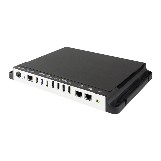
Page 14: Overview
1.6 Overview Front View Name Name DC Power Input Clearing EDID Button* Power Button HDMI Ports LED Indicators for GbE LAN Ports Power & HDD COM1 RS-232 Port Audio Line-Out Jack (RJ50 connector) USB 3.0 Port Wall Mounting Chassis USB 2.0 Port Be sure to press the EDID Button to acquire or change the EDID data when the connected display/monitor cannot be recognized, or the displayed image does not fit the screen. -
Page 15: Dimensions
General Information 1.7 Dimensions Unit: mm SI-324 User Manual... -
Page 16: Hardware Installation & Motherboard Information
Chapter 2 Hardware Installation & Motherboard Information The information provided in this chapter includes: Installation of memory, M.2 and mini PCIe cards Information and locations of connectors... -
Page 17: Installation / Replacement
Hardware Configuration 2.1 Installation / Replacement You need to remove the device bottom chassis firstly before installations. Remove 4 screws as indicated below and pull out the device bottom chassis to install or replace the 1 memory module, mini-PCIe card, M.2 M2280 & E2230 cards, and SIM card. -
Page 18: Memory
2. Remove 3 brass standoffs indicated by red circles and 3 screws indicated by blue circles to free up the motherbard. 2.1.1 Memory To install the modules, locate the memory slot on the motherboard and perform the following steps: 1. Press the ejector tab of the memory slot down and outwards with your fingertips. -
Page 19: Mini-Pcie & M.2 Cards
Hardware Configuration 2.1.2 Mini-PCIe & M.2 Cards 1. Locate the mini-PCIe or M.2 slot inside the device. 2. Align the key of the mini-PCIe card to the mini-PCIe interface, and insert the card slantwise. (Insert the M.2 card in the same way.) 3. -
Page 20: Mounting Installation
2.1.4 Mounting Installation Requirements Before mounting the system, ensure that you have enough room for the power adaptor and signal cable routing, and have good ventilation for the power adaptor. The method of mounting must be able to support weight of the SI-324 plus the weight of the suspending cables attached to the system. -
Page 21: Pin Assignment For Dc Power Input Connector
Hardware Configuration 2.2 Pin Assignment for DC Power Input Connector Assignment Assignment Ground Ground +12V +12V 2.3 Pin Assignment for COM1 RS-232 Port COM1 port is jumper-less and configurable in BIOS. Assignment Assignment DSR, Data set ready DCD, Data carrier detect Ground DTR, Data terminal ready Ground... -
Page 22: Setting The Jumpers
2.4 Setting the Jumpers Set up and configure your SI-324 by using jumpers for various settings and features according to your needs and applications. Contact your supplier if you have doubts about the best configuration for your use. 2.4.1 How to Set Jumpers Jumpers are short-length conductors consisting of several metal pins with a non-conductive base mounted on the circuit board. -
Page 23: Jumper & Connector Locations On Motherboard
Hardware Configuration 2.5 Jumper & Connector Locations on Motherboard Motherboard: MBD324 MBD324 – top and I/O MBD324 - bottom SI-324 User Manual... -
Page 24: Jumpers & Connectors Quick Reference
2.6 Jumpers & Connectors Quick Reference Jumpers: Function Connector Name Page COM1 RS-232 power selection Clearing CMOS data Connectors: Function Connector Name Page System fan power connector CPU fan power connector USB 3.0 port CN1, CN2 HDMI 2.0 port CN3, CN4, CN5, CN6 GbE LAN port CN7, CN8 USB 2.0 port... -
Page 25: Com1 Rs-232 Power (Jp2)
Hardware Configuration 2.6.1 COM1 RS-232 Power (JP2) Function Pin closed Illustration +12V (default) 2.6.2 Clearing CMOS Data (J2) Function Pin closed Illustration Normal (default) Clear CMOS SI-324 User Manual... -
Page 26: System Fan Power Connector (J8)
2.6.3 System Fan Power Connector (J8) Signal Name Ground +12V Rotation detection 2.6.4 CPU Fan Power Connector (J9) Signal Name Ground +12V Rotation detection SI-324 User Manual... -
Page 27: Chapter 3 Driver Installation
Chapter 3 Driver Installation The information provided in this chapter includes: AMD Radeon™ Graphics Driver Installation HD Audio Driver Installation LAN Driver Installation... -
Page 28: Introduction
3.1 Introduction This section describes the installation procedures for software drivers. The software drivers are available on IBASE website www.ibase.com.tw. Register as a member of our website to download all the necessary drivers and extract for installation. 3.2 AMD Radeon™ Graphics Driver Installation 1. -
Page 29: Hd Audio Driver Installation
Driver Installation 3.3 HD Audio Driver Installation 1. Run the Setup.exe file. 2. On the Welcome screen of the InstallShield Wizard, click Next for installation. 3. When the driver is completely installed, restart the computer for changes to take effect. SI-324 User Manual... -
Page 30: Lan Driver Installation
3.4 LAN Driver Installation 1. Run the Setup.exe file. 2. On the Welcome screen of the InstallShield Wizard, click Next. 3. Accept the license agreement and click Next to continue. 4. When the driver is completely installed, restart the computer for changes to take effect. -
Page 31: Chapter 4 Bios Setup
Chapter 4 BIOS Setup This chapter describes the different settings available in the AMI BIOS that comes with the board. The topics covered in this chapter are as follows: Main Settings Advanced Settings Chipset Settings Security Settings ... -
Page 32: Introduction
4.1 Introduction The BIOS (Basic Input/Output System) installed in the ROM of your computer system supports Intel® processors. The BIOS provides critical low-level support for standard devices such as disk drives, serial ports and parallel ports. It also provides password protection as well as special support for detailed fine-tuning of the chipset controlling the entire system. -
Page 33: Main Settings
BIOS Setup 4.3 Main Settings BIOS Setting Description System Date Sets the date. Use the <Tab> key to switch between the data elements. System Time Set the time. Use the <Tab> key to switch between the data elements. 4.4 Advanced Settings This section allows you to configure, improve your system and allows you to set up some system features according to your preference. -
Page 34: Acpi Settings
4.4.1 ACPI Settings BIOS Setting Description Enable ACPI Auto Enables / Disables BIOS ACPI auto configuation. Configuration Enable Hibernation Enables / Disables system ability to hibernate (OS/S4 Sleep State). This option may not be effective with some operating systems. ACPI Sleep State Selects the highest ACPI sleep state the system will enter when the SUSPEND button is pressed. -
Page 35: Ismart Controller
BIOS Setup 4.4.3 iSmart Controller BIOS Setting Description Power-On after Power Enables / Disables the system to be turned on failure automatically after a power failure. PWR Resume Delay Enables / Disables power on resume delay. Temperature Guardian Enables / Disables the temperature guardian. Schedule Slot 1 / 2 Sets up the hour / minute for system powe-on. -
Page 36: F81846 Super Io Configuration
4.4.4 F81846 Super IO Configuration BIOS Setting Description Serial Ports Configuration Sets parameters of Serial Port (COM). Enables / Disables the serial port and select an optimal setting for the Super IO device. SI-324 User Manual... -
Page 37: Hardware Monitor
BIOS Setup 4.4.5 Hardware Monitor BIOS Setting Description CPU Smart Fan Control Disable or set fan control for CPU_FAN1 at 50°C, 60°C, 70°C or 80°C. System Smart Fan Disable or set fan control for CPU_FAN2 at Control 50°C, 60°C, 70°C or 80°C. Temperatures / Voltages These fields are the parameters of the hardware monitoring function feature of the... -
Page 38: Cpu Configuration
4.4.6 CPU Configuration BIOS Setting Description Node 0 Information Displays the memory information related to Node 0. 4.4.7 AMI Graphic Output Protocol Policy BIOS Setting Description Output Selection Selects an output interface. SI-324 User Manual... -
Page 39: Network Stack Configuration
BIOS Setup 4.4.8 Network Stack Configuration BIOS Setting Description Network Stack Enables / Disables UEFI Network Stack. 4.4.9 CSM Configuration BIOS Setting Description CSM Support Enables / Disables CSM support. Network Controls the execution of UEFI and Legacy PXE OpROM. Options: Do not launch, UEFI, Legacy SI-324 User Manual... -
Page 40: Usb Configuration
4.4.10 USB Configuration BIOS Setting Description Legacy USB Support Enable: Enables Ledacy USB Support. Auto: Disables legacy support if no USB devices are connected. Disable: Keeps USB devices available only for EFI applications. XHCI Hand-off This is a workaround for OSes without XHCI hand-off support. -
Page 41: Chipset Settings
BIOS Setup 4.5 Chipset Settings BIOS Setting Description Sourth Bridge South Bridge parameters SB USB Configuration Options for SB USB configuration. SI-324 User Manual... - Page 42 4.5.1 SB USB Configuration BIOS Setting Description XHCI0 / XHCI1 Ports Enables / Disables XHCI0 / XHCI1 ports. SI-324 User Manual...
-
Page 43: Security Settings
BIOS Setup 4.6 Security Settings BIOS Setting Description Administrator Password Sets an administrator password for the setup utility. User Password Sets a user password. Secure Boot Custimizable secure boot settings. SI-324 User Manual... - Page 44 4.6.1 Secure Boot Configuration BIOS Setting Description Secure Boot Secure Boot is activated when it is enabled, when the Platform Key (PK) is enrolled, the System mode is user deployed, and CSM is disabled. Secure Boot Customizable Secure Boot mode: In Custom Customization mode, Secure Boot policy variables can be configured by a physically present user without...
-
Page 45: Boot Settings
BIOS Setup 4.7 Boot Settings BIOS Setting Description Setup Prompt Timeout Number of seconds to wait for setup activation key. 65535 (0xFFFF) means indefinite waiting. Bootup NumLock State Selects the keyboard NumLock state. Quiet Boot Enables / Disables Quiet Boot option. Boot Mode Select Select boot mode as Legacy or UEFI. -
Page 46: Save & Exit Settings
4.8 Save & Exit Settings BIOS Setting Description Save Changes and Exit Exits system setup after saving the changes. Discard Changes and Exit Exits system setup without saving any changes. Save Changes and Reset Resets the system after saving the changes. Discard Changes and Resets system setup without saving any Reset... -
Page 47: Appendix
Appendix This section provides the mapping addresses of peripheral devices and the sample code of watchdog timer configuration. SDR and HDR Resolution Support AMD Eyefinity Multiple Displays I/O Port Address Map Interrupt Request Lines (IRQ) Watchdog Timer Configuration... -
Page 48: Sdr And Hdr Resolution Support
SDR and HDR Resolution Support Maximum SDR Resolution (Clone/Extended mode) Dual Channel: 1 display: 2880p60 / 4320p30 2 displays: 2880p60 / 4320p30 3 displays: 2160p60 4 displays: 2160p60 Single Channel: 1 display: 2880p60 / 4320p30 ... -
Page 49: Amd Eyefinity Multiple Displays Configuration
Appendix AMD Eyefinity Multiple Displays Configuration AMD Eyefinity is applicable to SI-324; it is a technology that allows two or more displays to be grouped together to form a single large desktop. Once AMD Eyefinity is configured, the final resolution is the horizontal and/or vertical sum of the individual monitors. - Page 50 2. Click Eyefinity once AMD Radeon Settings opens. 3. Click Quick Setup to automatically create an AMD Eyefinity Display Group based on the current (default) display configuration. Note: At the time of writing, Advanced Setup for configuring Eyefinity is available. However, this feature is not supported. Do not confuse with Try Advanced Setup (see below picture), which becomes available after Eyefinity Quick Setup is complete.
- Page 51 Appendix 4. In this example, a 3x1 Eyefinity Display Group is created as shown below. 5. Once the AMD Eyefinity Display Group is created, the following options become available: Discard – Removes the AMD Eyefinity setup and restores the previous display configuration.
- Page 52 2. The onscreen guide will show a grid representation of the Eyefinity Display Group and one of the physical displays will have a blue background. 3. Click on the box in the grid that matches the desired location of the highlighted display in blue.
-
Page 53: Customizing Amd Eyefinity Using Try Advanced Setup
Appendix 2. Follow the steps in Section 2.1, “AMD Eyefinity Quick Setup with All Displays” to configure Eyefinity. In this example, a 3 x 1 Eyefinity Display Group has been created with 3 x 4k displays after Eyefinity Quick Setup is complete. 3. - Page 54 To set the Taskbar position: 1. Click Try Advanced Setup (under Eyefinity tab in AMD Radeon Settings) after Eyefinity Quick Setup is complete. 2. Click Position Windows Taskbar once Radeon Additional Settings launches. 3. Check the Position the Windows taskbar on a single display option and click Continue.
- Page 55 Appendix B.2.2 Arrange Eyefinity Display Group The Arrange Eyefinity Display Group option allows re-arranging the order of the displays in an AMD Eyefinity Display Group if needed. To re-arrange the displays in an Eyefinity Display Group: 1. Click Try Advanced Setup (under Eyefinity tab in AMD Radeon Settings) after Eyefinity Quick Setup is complete.
- Page 56 3. Choose one of the following options: Fill - Fill the entire area of each display with its portion of the desktop. The desktop may appear stretched on certain displays. Fit - Resize the desktop to the height of the shortest display. Show the entire desktop across all displays without cropping or stretching the desktop.
- Page 57 Appendix 4. Click on the directional arrow: Then click No for the “Are the test patterns correct?” box to repeat Step #3 for the next set of bezels. 5. When complete, click the X button and Yes to save the changes and close the tool.
- Page 58 3. In the Customize Eyefinity Desktop Resolution menu, the minimum and maximum resolutions are automatically determined based on your displays and cannot be changed. Use the Custom Resolution drop-down menu to select from a list of supported resolutions. 4. Select the preferred resolution from the Custom Resolution drop-down menu, and click Apply to save the setting.
-
Page 59: I/O Port Address Map
Appendix C. I/O Port Address Map Each peripheral device in the system is assigned a set of I/O port addresses which also becomes the identity of the device. The following table lists the I/O port addresses used. Address Device Description 0x00000A00-0x00000A0F Motherboard resources 0x00000A10-0x00000A1F... - Page 60 Address Device Description 0x00000088-0x00000088 Motherboard resources 0x0000008C-0x0000008E Motherboard resources 0x00000090-0x0000009F Motherboard resources 0x000000A2-0x000000BF Motherboard resources 0x000000B1-0x000000B1 Motherboard resources 0x000000E0-0x000000EF Motherboard resources 0x000004D0-0x000004D1 Motherboard resources 0x0000040B-0x0000040B Motherboard resources 0x000004D6-0x000004D6 Motherboard resources 0x00000C00-0x00000C01 Motherboard resources 0x00000C14-0x00000C14 Motherboard resources 0x00000C50-0x00000C51 Motherboard resources 0x00000C52-0x00000C52 Motherboard resources 0x00000C6C-0x00000C6C Motherboard resources...
-
Page 61: Interrupt Request Lines (Irq)
Appendix D. Interrupt Request Lines (IRQ) Peripheral devices use interrupt request lines to notify CPU for the service required. The following table shows the IRQ used by the devices on board. Level Function IRQ 4294967292 PCI Express Root Port IRQ 0 High precision event timer IRQ 0 System timer... - Page 62 Level Function IRQ 55 AMD SFH KMDF I2C IRQ 56 ~ IRQ 204 Microsoft ACPI-Compliant System IRQ 256 ~ IRQ 511 Microsoft ACPI-Compliant System IRQ 4294967287 Realtek PCIe GBE Family Controller #2 IRQ 4294967294 PCI Express Root Port IRQ 4294967293 PCI Express Root Port IRQ 4294967291 PCI Express Root Port...
-
Page 63: Watchdog Timer Configuration
Appendix E. Watchdog Timer Configuration The Watchdog Timer (WDT) is used to generate a variety of output signals after a user programmable count. The WDT is suitable for the use in the prevention of system lock-up, such as when software becomes trapped in a deadlock. - Page 64 //--------------------------------------------------------------------------- void EnableWDT(int interval) unsigned char bBuf; bBuf = Get_F81846_Reg(0x2B); bBuf &= (~0x20); Set_F81846_Reg(0x2B, bBuf); //Enable WDTO Set_F81846_LD(0x07); //switch to logic device 7 Set_F81846_Reg(0x30, 0x01); //enable timer bBuf = Get_F81846_Reg(0xF5); bBuf &= (~0x0F); bBuf |= 0x52; Set_F81846_Reg(0xF5, bBuf); //count mode is second Set_F81846_Reg(0xF6, interval);...
- Page 65 Appendix F81846_BASE = 0x4E; result = F81846_BASE; ucDid = Get_F81846_Reg(0x20); if (ucDid == 0x07) //Fintek 81846 goto Init_Finish; } F81846_BASE = 0x2E; result = F81846_BASE; ucDid = Get_F81846_Reg(0x20); if (ucDid == 0x07) //Fintek 81846 goto Init_Finish; } F81846_BASE = 0x00; result = F81846_BASE;...
- Page 66 //--------------------------------------------------------------------------- // THIS CODE AND INFORMATION IS PROVIDED "AS IS" WITHOUT WARRANTY OF ANY // KIND, EITHER EXPRESSED OR IMPLIED, INCLUDING BUT NOT LIMITED TO THE // IMPLIED WARRANTIES OF MERCHANTABILITY AND/OR FITNESS FOR A PARTICULAR // PURPOSE. //--------------------------------------------------------------------------- #ifndef F81846_H #define F81846_H...
Need help?
Do you have a question about the SI-324-12 and is the answer not in the manual?
Questions and answers