IBASE Technology SI-313 User Manual
Digital signage player
Hide thumbs
Also See for SI-313:
- User manual (68 pages) ,
- User manual (71 pages) ,
- User manual (71 pages)
Table of Contents
Advertisement
Quick Links
Advertisement
Table of Contents

Related Manuals for IBASE Technology SI-313


Summary of Contents for IBASE Technology SI-313
- Page 1 SI-313 Digital Signage Player User’s Manual Version 1.0 (May 2017)
- Page 2 No part of this publication may be reproduced, copied, stored in a retrieval system, translated into any language or transmitted in any form or by any means, electronic, mechanical, photocopying, or otherwise, without the prior written consent of IBASE Technology, Inc. (hereinafter referred to as “IBASE”).
-
Page 3: Compliance
0.1% by weight (1000 ppm) except for cadmium, limited to 0.01% by weight (100 ppm). • Lead (Pb) • Mercury (Hg) • Cadmium (Cd) • Hexavalent chromium (Cr6+) • Polybrominated biphenyls (PBB) • Polybrominated diphenyl ether (PBDE) SI-313 User Manual... -
Page 4: Important Safety Information
You are not suggested to disassemble, repair or make any modification to the device. Disassembly, modification, or any attempt at repair could generate hazards and cause damage to the device, even bodily injury or property damage, and will void any warranty. SI-313 User Manual... -
Page 5: Caution
Software in use (such as OS and application software, including the version numbers) 3. If repair service is required, you can download the RMA form at http://www.ibase.com.tw/english/Supports/RMAService/. Fill out the form and contact your distributor or sales representative. SI-313 User Manual... -
Page 6: Table Of Contents
Power Button (SW1) ............21 2.5.2 EDID Clearance Button (SW2) ..........21 2.5.3 LED Indicators for Power & HDD (LED4, LED5) ....22 2.5.4 DC Power Input (CN1) ............22 2.5.5 HDMI 2.0 Port (CN2, CN3, CN4) .......... 23 SI-313 User Manual... - Page 7 SATA Configuration ..............43 4.4.8 CSM Configuration ..............44 4.4.9 USB Configuration ..............45 Chipset Settings ..................46 4.5.1 South Bridge ................47 4.5.2 North Bridge ................48 Security Settings ................... 49 Boot Settings..................50 Save & Exit Settings................51 SI-313 User Manual...
- Page 8 Appendix ...................... 52 I/O Port Address Map ................53 Interrupt Request Lines (IRQ) ............... 56 Watchdog Timer Configuration .............. 57 viii SI-313 User Manual...
-
Page 9: Chapter 1 General Information
Chapter 1 General Information The information provided in this chapter includes: • Features • Packing List • Specifications • Optional Accessories • Overview • Dimensions... -
Page 10: Introduction
1.1 Introduction SI-313, a product code of IBASE digital signage player series, is a mid-range system with iSMART and capable of auto-scheduling for general applications. It is designed with the feature of segregated flow ventilation. The device is powered by the AMD 3 Gen. -
Page 11: Packing List
General Information 1.3 Packing List Your SI-313-N package should include the items listed below. If any of the items below is missing, contact the distributor or the dealer from whom you purchased the product. • SI-313 Digital Signage Player (with Rack Mount Kit) •... -
Page 12: Specifications
Mounting Slim design with wall mount holes Dimensions 215.6 x 33 x 150 mm (8.49” x 1.3” x 5.9”) (W x H x D) Net Weight 1.55 kg (3.42 lb) Certificate CE, FCC Class B, UL, CCC SI-313 User Manual... - Page 13 Operating: 0 ~ 45 °C (32 ~ 113 °F) Temperature • Storage: --20 ~ 80 °C (-4 ~ 176 °F) Relative 10 ~ 90% (non-condensing) Humidity Vibration M.2: Operating, random vibration 5 grms (5~500Hz) Protection All specifications are subject to change without prior notice. SI-313 User Manual...
-
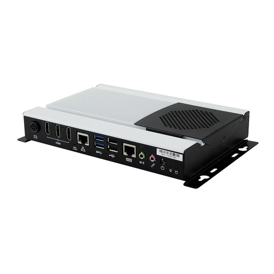
Page 14: Overview
1.6 Overview Top View Oblique View SI-313 User Manual... - Page 15 Be sure to press the EDID Clearance Button shortly so as to clear the EDID register if any connected display/monitor is unable to be recognized, or when the image displayed cannot not be resampled to fit the screen. SI-313 User Manual...
-
Page 16: Dimensions
1.7 Dimensions Unit: mm SI-313 User Manual... -
Page 17: Hardware Installation & Motherboard Information
Chapter 2 Hardware Installation & Motherboard Information The information provided in this chapter includes: • Essential installations before you begin • Information and locations of connectors... -
Page 18: Essential Installations Before You Begin
2.1 Essential Installations Before You Begin 2.1.1 Memory Installation There are two SO-DIMM DDR4 memory slots inside SI-313 for a maximum total memory of 32 GB. To install the modules, locate the memory slot on the board and perform the following steps: 1. -
Page 19: Mini Pcie & M.2 Network Cards Installation
1. Align the key of the mini PCIe card to the Mini PCIe interface, and insert the card slantwise. (Insert the M.2 network card in the same way.) 2. Push the mini PCIe card down, fix it with 2 screws. (Fix the M.2 network card with a screw.) Mini PCIe: M.2: SI-313 User Manual... -
Page 20: Wifi / 3G / 4G Antenna Installation
1. Thread and fasten the hex nut and the 2. Apply adhesive around here. washer. Then install the antenna. Info: The diameter of the nut is around 6.35 mm (0.25”-36UNC). SI-313 User Manual... -
Page 21: Wall Mount Installation
When mounting, ensure that you have enough room for power and signal cable routing, and have good ventilation for power adapter. The method of mounting must be able to support weight of the SI-313 plus the suspension weight of all the cables to be attached to the system. Use the following... - Page 22 Prepare at least 4 screws (M3) to install the device on wall as below. You can install your SI-313 on plastic (LCD monitor), wood, drywall surface over studs, or a solid concrete or metal plane directly. The types of fasteners required are dependent on the type of wall construction.
-
Page 23: Setting The Jumpers
Motherboard Information 2.2 Setting the Jumpers Set up and configure your SI-313 by using jumpers for various settings and features according to your needs and applications. Contact your supplier if you have doubts about the best configuration for your use. -
Page 24: Jumper & Connector Locations On Motherboard
2.3 Jumper & Connector Locations on Motherboard Motherboard: MBD313 Gen. Embedded R-Series SOC APU MBD313 - top SI-313 User Manual... - Page 25 Motherboard Information Battery MBD313 - bottom SI-313 User Manual...
-
Page 26: Jumpers Quick Reference
2.4 Jumpers Quick Reference Jumper: Function Connector Name Page CMOS Data Clearance ATX / AT Power Mode Selection 2.4.1 CMOS Data Clearance (JP1) Function Pin closed Illustration Normal (default) Clear CMOS SI-313 User Manual... -
Page 27: Atx / At Power Mode Connector (Jp2)
Motherboard Information 2.4.2 ATX / AT Power Mode Connector (JP2) Function Pin closed Illustration (default) SI-313 User Manual... -
Page 28: Connectors Quick Reference
COM2 RS232 Port System Function Connector NGFF M.2 Connector J6 (M-KEY 2280) J13 (B-KEY 3042) SIM Card Socket Mini PCIE Connectors DDR4 SO-DIMM J11, J12 Digital I/O Header Factory Use Only J7, J9, J14, J15, J16, J17, J18 SI-313 User Manual... -
Page 29: Power Button (Sw1)
Note: Be sure to press this button shortly so as to clear the EDID register if any connected display/monitor is unable to be recognized, or when the image displayed cannot not be resampled to fit the screen. SI-313 User Manual... -
Page 30: Led Indicators For Power & Hdd (Led4, Led5)
LED4 is the red LED indicator for power status. It stays on (not blinks) as the device is on. LED5 is the green LED indicator for HDD. When HDD is being read, it blinks. 2.5.4 DC Power Input (CN1) Assigment Assigment Ground +12V Ground +12V SI-313 User Manual... -
Page 31: Hdmi 2.0 Port (Cn2, Cn3, Cn4)
Motherboard Information 2.5.5 HDMI 2.0 Port (CN2, CN3, CN4) 2.5.6 LAN Port (CN5) 2.5.7 Dual USB 3.0 Ports (CN6) SI-313 User Manual... -
Page 32: Dual Usb 2.0 Ports (Cn7)
Dual USB 2.0 Ports (CN7) 2.5.9 COM1 RS-232 Port (CN8) Assigment Assigment DSR (Data set ready) DCD (Data carrier detect) Ground DTR (Data terminal ready) Ground CTS (Clear to send) TX (Transmit) RTS (Request to send) RX (Receive) RI (Ring indicator) SI-313 User Manual... -
Page 33: Audio Jack (Cn9, Cn10)
Motherboard Information 2.5.10 Audio Jack (CN9, CN10) CN9: Line-out CN10: Microphone Input 2.5.11 CPU Fan Power Connector (J1) Assigment Ground +12V Rotation detection SI-313 User Manual... -
Page 34: Usb 2.0 Ports Header (J2)
2.5.13 COM2 RS-232 Port (J3) Assigment Assigment DCD (Data carrier detect) CTS (Clear to send) DSR (Data set ready) DTR (Data terminal ready) RXD (Receive data) RI (Ring indicator) RTS (Request to send) Ground TXD (Transmit data) SI-313 User Manual... -
Page 35: System Function Connector (J4)
HDD LED+ HDD LED- +5VSB 2.5.15 NGFF M.2 Connector (J6, J13) J6 is a M.2 M-Key (2280) connector with SATA. J13 is a M.2 B-Key (3042) connector with PCIe (x2) , USB 2.0, USB 3.0, and SATA. SI-313 User Manual... -
Page 36: Sim Card Socket (J8)
2.5.16 SIM Card Socket (J8) 2.5.17 Mini PCIe Connector (J10) J10 is a Mini PCIe connector with PCI-e, USB and SIM. 2.5.18 DDR4 SO-DIMM (J11, J12) SI-313 User Manual... -
Page 37: Digital I/O Connector (J19)
Motherboard Information 2.5.19 Digital I/O Connector (J19) Assigmentd Assigment Ground OUT0 OUT3 OUT1 OUT2 SI-313 User Manual... -
Page 38: Chapter 3 Driver Installation
Chapter 3 Driver Installation The information provided in this chapter includes: • AMD Merlin Falcon Graphics Drivers Installation • HD Audio Driver Installation • LAN Driver Installation... -
Page 39: Introduction
Merlin Falcon Graphics Drivers Installation. 2. Click Install to cintinue. 3. Select the desired drivers and click Install. 4. The driver has been completely installed. You are suggested to restart the computer for changes to take effect. SI-313 User Manual... -
Page 40: Hd Audio Driver Installation
2. On the Welcome screen of the InstallShield Wizard, click Next. 3. After reading the descriptions of the setup options, click Next to start installation. 4. The driver has been completely installed. You are suggested to restart the computer and for changes to take effect. SI-313 User Manual... -
Page 41: Lan Driver Installation
Realtek GbE _FE Ethernet PCI-E NIC Driver. 2. When the Welcome screen appears, click Next and then Install to contiune installation. 3. The driver has been completely installed. You are suggested to restart the computer for changes to take effect. SI-313 User Manual... -
Page 42: Chapter 4 Bios Setup
Chapter 4 BIOS Setup This chapter the different settings available in the AMI describes BIOS that comes with the board. The topics covered in this chapter are as follows: • Main Settings • Advanced Settings • Chipset Settings • Security Settingss •... -
Page 43: Introduction
These defaults have been carefully chosen by both AMI and your system manufacturer to provide the absolute maximum performance and reliability. Changing the defaults could make the system unstable and crash in some cases. SI-313 User Manual... -
Page 44: Main Settings
System Language Choose the system default language. System Date Sets the date. Use the <Tab> key to switch between the data elements. System Time Set the time. Use the <Tab> key to switch between the data elements. SI-313 User Manual... -
Page 45: Advanced Settings
BIOS Setup 4.4 Advanced Settings This section allows you to configure, improve your system and allows you to set up some system features according to your preference. SI-313 User Manual... -
Page 46: Ide Configuration
4.4.1 IDE Configuration 4.4.2 ACPI Shutdown Temperature SI-313 User Manual... -
Page 47: Ismart Controller
Controller BIOS Setting Description Power-On after Power Enables / Disables the system to be turned on failure automatically after a power failure. Schedule Slot 1 / 2 Sets up the hour / minute for system powe-on. SI-313 User Manual... -
Page 48: Super Io Configuration
4.4.4 Super IO Configuration BIOS Setting Description Serial Port Configuration Sets parameters of Serial Ports (COMA). Enables / Disables the serial port and select an optimal setting for the Super IO device. SI-313 User Manual... -
Page 49: Hardware Monitor
These fields are the parameters of the hardware monitoring function feature of the motherboard. The values are read-only values as monitored by the system and show the PC health status. Shutdown Temperature This field enables or disables the Shutdown Temperature SI-313 User Manual... -
Page 50: Cpu Configuration
4.4.6 CPU Configuration BIOS Setting Description Node 0 Information Shows the memory information related to Node 0. SI-313 User Manual... -
Page 51: Sata Configuration
SATA Controller(s) Enables / Disables SATA devices. SATA Mode Selection Determines how the SATA controller(s) operate. • AHCI Mode. • RAID Mode. Serial ATA Ports Enables / Disables Serial Ports. Hot Plug Designates this port as Hot Pluggable. SI-313 User Manual... -
Page 52: Csm Configuration
4.4.8 CSM Configuration BIOS Setting Description CSM Support Enables or disables CSM support. SI-313 User Manual... -
Page 53: Usb Configuration
The maximum time the device will take before it properly reports itself to the Host Controller. “Auto” uses default value for a Root port it is 100ms. But for a Hub port, the delay is taken from Hub descriptor. SI-313 User Manual... -
Page 54: Chipset Settings
4.5 Chipset Settings BIOS Setting Description Sourth Bridge South Bridge parameters North Bridge North Bridge parameters SI-313 User Manual... -
Page 55: South Bridge
BIOS Setup 4.5.1 South Bridge 4.5.1.1. SATA Configuration BIOS Setting Description SB SATA / USB Options for SATA Configuration Configuration SI-313 User Manual... -
Page 56: North Bridge
4.5.1.2. XHCI Controller 4.5.2 North Bridge BIOS Setting Description Socket 0 Information Displays the information related to Socket 0.. SI-313 User Manual... -
Page 57: Security Settings
BIOS Setup 4.6 Security Settings BIOS Setting Description Administrator Password Sets an administrator password for the setup utility. User Password Sets a user password. SI-313 User Manual... -
Page 58: Boot Settings
Enables / Disables boot with initialization of a minimal set of devices required to launch the active boot option. There no effect for BBS boot options. Fixed Boot Order Sets the system boot order. Priorities Boot Option Priorities Sets the system boot order. SI-313 User Manual... -
Page 59: Save & Exit Settings
Restore Defaults Restores / Loads defaults values for all the setup options. Save as User Defaults Saves the changes done so far as user defaults. Restore User Defaults Restores the user defaults to all the setup options. SI-313 User Manual... -
Page 60: Appendix
Appendix This section provides the mapping addresses of peripheral devices and the sample code of watchdog timer configuration. • I/O Port Address Map • Interrupt Request Lines (IRQ) • Digital I/O Sample Code • Watchdog Timer Configuration... -
Page 61: I/O Port Address Map
PCI Express Root Complex 0x000003B0-0x000003DF AMD Radeon R7 Graphics 0x00000D00-0x0000FFFF PCI Express Root Complex 0x0000F000-0x0000F0FF AMD Radeon R7 Graphics 0x000003C0-0x000003DF AMD Radeon R7 Graphics 0x00000040-0x00000043 System timer 0x0000F140-0x0000F147 Standard SATA AHCI Controller 0x0000F130-0x0000F133 Standard SATA AHCI Controller SI-313 User Manual... - Page 62 Motherboard resources 0x000004D6-0x000004D6 Motherboard resources 0x00000C00-0x00000C01 Motherboard resources 0x00000C14-0x00000C14 Motherboard resources 0x00000C50-0x00000C51 Motherboard resources 0x00000C52-0x00000C52 Motherboard resources 0x00000C6C-0x00000C6C Motherboard resources 0x00000C6F-0x00000C6F Motherboard resources 0x00000CD0-0x00000CD1 Motherboard resources 0x00000CD2-0x00000CD3 Motherboard resources 0x00000CD4-0x00000CD5 Motherboard resources 0x00000CD6-0x00000CD7 Motherboard resources 0x00000CD8-0x00000CDF Motherboard resources SI-313 User Manual...
- Page 63 Appendix Address Device Description 0x00000800-0x0000089F Motherboard resources 0x00000B20-0x00000B3F Motherboard resources 0x00000900-0x0000090F Motherboard resources 0x00000910-0x0000091F Motherboard resources 0x0000FE00-0x0000FEFE Motherboard resources 0x00000061-0x00000061 System speaker SI-313 User Manual...
-
Page 64: Interrupt Request Lines (Irq)
AMD USB 3.0 eXtensible Host Controller - 1.0 (Microsoft) IRQ 4294967291 AMD USB 3.0 eXtensible Host Controller - 1.0 (Microsoft) IRQ 4294967292 AMD PSP 2.0 Device IRQ 4294967293 AMD PSP 2.0 Device IRQ 4294967294 PCI Express Root Port SI-313 User Manual... -
Page 65: Watchdog Timer Configuration
Fintek 81866, program abort.\n"); return(1); }//if (SIO == 0) if (argc != 2) printf(" Parameter incorrect!!\n"); return (1); bTime = strtol (argv[1], endptr, 10); printf("System will reset after %d seconds\n", bTime); if (bTime) EnableWDT(bTime); } else DisableWDT(); } return 0; SI-313 User Manual... - Page 66 //--------------------------------------------------------------------------- void DisableWDT(void) unsigned char bBuf; Set_F81866_LD(0x07); //switch to logic device 7 bBuf = Get_F81866_Reg(0xFA); bBuf &= ~0x01; Set_F81866_Reg(0xFA, bBuf); //disable WDTO output bBuf = Get_F81866_Reg(0xF5); bBuf &= ~0x20; bBuf |= 0x40; Set_F81866_Reg(0xF5, bBuf); //disable WDT //--------------------------------------------------------------------------- SI-313 User Manual...
- Page 67 Init_Finish; } F81866_BASE = 0x00; result = F81866_BASE; Init_Finish: return (result); //--------------------------------------------------------------------------- void Unlock_F81866 (void) outportb(F81866_INDEX_PORT, F81866_UNLOCK); outportb(F81866_INDEX_PORT, F81866_UNLOCK); //--------------------------------------------------------------------------- void Lock_F81866 (void) outportb(F81866_INDEX_PORT, F81866_LOCK); //--------------------------------------------------------------------------- void Set_F81866_LD( unsigned char LD) Unlock_F81866(); outportb(F81866_INDEX_PORT, F81866_REG_LD); outportb(F81866_DATA_PORT, LD); Lock_F81866(); SI-313 User Manual...
- Page 68 //--------------------------------------------------------------------------- #defineF81866_INDEX_PORT (F81866_BASE) #defineF81866_DATA_PORT (F81866_BASE+1) //--------------------------------------------------------------------------- #defineF81866_REG_LD 0x07 //--------------------------------------------------------------------------- #define F81866_UNLOCK 0x87 #defineF81866_LOCK 0xAA //--------------------------------------------------------------------------- unsigned int Init_F81866(void); void Set_F81866_LD( unsigned char); void Set_F81866_Reg( unsigned char, unsigned char); unsigned char Get_F81866_Reg( unsigned char); //--------------------------------------------------------------------------- #endif // F81866_H SI-313 User Manual...
Need help?
Do you have a question about the SI-313 and is the answer not in the manual?
Questions and answers