Table of Contents
Advertisement
Quick Links
Advertisement
Table of Contents

Related Manuals for IBASE Technology SI-28 Series


Summary of Contents for IBASE Technology SI-28 Series
-
Page 1: User Manual
SI-28 Series User Manual 2009 October V0.A1... - Page 2 Copyright © 2008 IBASE Technology INC. All Rights Reserved. No part of this manual, including the products and software described in it, may be reproduced, transmitted, transcribed, stored in a retrieval system, or translated into any language in any form or by any means, except documentation kept by the purchaser for backup purposes, without the express written permission of IBASE Technology INC.
-
Page 3: Table Of Contents
Table of Contents Acknowledgments ....................6 Accessories ......................7 Components ......................8 I/O View ........................8 Specification ......................10 Mounting SI-28 to the Wall ................... 11 Wall mounting requirements ..................11 Selecting the location ....................12 Exploded view of the SI-28 assembly ..............13 Parts description ...................... -
Page 4: Safety Information
Safety Information Your SI-28 is designed and tested to meet the latest standards of safety for information technology equipment. However, to ensure your safety, it is important that you read the following safety instructions. Setting up your system Read and follow all instructions in the documentation before you operate your system. - Page 5 The system was dropped or the cabinet is damaged. Lithium-Ion Battery Warning CAUTION: Danger of explosion if battery is incorrectly replaced. Replace only with the same or equivalent type recommended by the manufacturer. Dispose of used batteries according to the manufacturer‟s instructions. NO DISASSEMBLY The warranty does not apply to the products that have been disassembled by users...
-
Page 6: Acknowledgments
Acknowledgments Award is a registered trademark of Award Software International, Inc. PS/2 is a trademark of International Business Machines Corporation. AMD Athlon™ 64 / Athlon™ 64 x2 (dual core) / Sempron™ processors are registered trademarks of AMD Corporation. ... -
Page 7: Accessories
Accessories Power Cord x 1 System Manual x 1 Driver CD x 1 Power Brick x 1... -
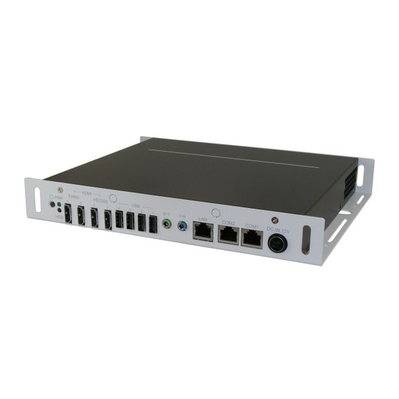
Page 8: Components
Components I/O View Refer to the diagram below to identify the components on this side of the system. The power switch allows powering ON and OFF the system. The hard disk LED blinks when data is being written into or read from the hard disk drive. - Page 9 The stereo audio jack (3.5mm) is used to connect the system‟s audio out signal to amplified speakers or headphones. The eight-pin RJ-45 LAN port supports a standard Ethernet cable for connection to a local network. COM1 / COM2 Communication or serial port is compatible with RS-232 interface without RI (ring indicator) signal.
-
Page 10: Specification
Specification System Mainboard IB-828 Construction Aluminum Chassis Color Black / White Storage 2.5” 80GB SATA HDD x 1 Mounting Wall mount Dimensions 250(W) x 35(H) x 210(D)mm (9.84” x 1.38” x 8.27”) Power Supply 150W DC adapter Operating Temperature 0°C ~ 45°C (32°F ~ 113°F) Storage Temperature -20°C ~ 80°C Relative Humidity... -
Page 11: Mounting Si-28 To The Wall
Mounting SI-28 to the Wall You can install SI-28 on wood, drywall surface over studs, or a solid concrete or metal plane directly. Ensure the installer uses at least four M3 length 8mm screws to secure the system on wall. Six M3 length 8mm screws are recommended to secure the system on wall. -
Page 12: Selecting The Location
Mounting to hollow walls Method 1: Wood surface – A minimum wood thickness – 38mm (1.5in.) by 25.4 cm (10in.) – of high, construction – grade wood is recommended. Note: This method provides the most reliable attachment of the unit with little risk that the unit will come loose or require ongoing maintenance. -
Page 13: Exploded View Of The Si-28 Assembly
Exploded view of the SI-28 assembly Parts description Part NO. Description Part NO. Description 1 Heat sink 2 IB828 3 HDD tray bracket 4 HDD 5 HDD side wall bracket 6 Bottom chassis 7 System FAN 8 System FAN bracket 9 Top Cover... -
Page 14: Installation
Installation Installing the memory The IB828 board supports one DDR2 memory socket that can support up to 4GB memory size, DDR2 400/533/667 (w/o ECC function). Installing and Removing Memory Modules To install the DDR2 modules, locate the memory slot on the board and perform the following steps: Hold the DDR2 module so that the key of the DDR2 module aligns with that on the memory slot. -
Page 15: Installing The Cpu
Installing the CPU The IB828 board supports a Socket AM2 (940-pin) processor socket for AMD Athlon™ 64 / Athlon™ 64 x2 (dual core) / Sempron™ processors. To install the CPU, unlock first the socket by pressing the lever sideways, then lift it up to a 90-degree angle as shown below. -
Page 16: Setting Jumper
Setting Jumper Jumpers are used on IB828 to select various settings and features according to your needs and applications. Contact your supplier if you have doubts about the best configuration for your needs. The following lists the connectors on IB828 and their respective functions Jumper Locations on IB828 JP2: ATX or AT Power Selection... - Page 17 JP4, JP5, JP6: RS232/422/485 (COM2) Selection COM1 is fixed for RS-232 use only. COM2 is selectable for RS232, RS-422 and RS-485. The following describes the settings for COM2. COM2 RS-232 RS-422 RS-485 Function JP4: JP4: JP4: Jumper JP5: JP5: JP5: Setting 3-5 &...
-
Page 18: Bios Setup
BIOS Setup This chapter describes the different settings available in the Award BIOS that comes with the board. BIOS Introduction The Award BIOS (Basic Input / Output System) installed in your computer system‟s ROM supports various processors. The BIOS provides critical low-level support for a standard device such as disk drives, serial ports and parallel ports. - Page 19 The section below the setup items of the Main Menu displays the control keys for this menu. At the bottom of the Main Menu just below the control keys section, there is another section, which displays information on the currently highlighted item in the list. Note: If the system cannot boot after making and saving system changes with Setup, the Award BIOS supports an override to the CMOS settings that resets your system to its default.
- Page 20 Standard CMOS Setup “Standard CMOS Setup” choice allows you to record some basic hardware configurations in your computer system and set the system clock and error handling. If the motherboard is already installed in a working system, you will not need to select this option.
- Page 21 set the current time. The time format is: Hour: 00 to 23 Minute: 00 to 59 Second: 00 to 59 IDE Channel Master/Slave The onboard PCI IDE connector provides Primary and Secondary channels for connecting up to two IDE hard disks or other IDE devices. Press <Enter>...
- Page 22 errors All, But Diskette: The system boot will not be halted for a disk error; it will stop for all other errors. All, But Disk/Key: The system boot will not be halted for a key- board or disk error; it will stop for all others.
- Page 23 Advanced BIOS Features This section allows you to configure and improve your system and allows you to set up some system features according to your preference. CPU Feature Press Enter to configure the settings relevant to CPU Feature. Hard Disk Boot Priority With the field, there is the option to choose, aside from the hard disks connected, “Bootable add-in Cards”...
- Page 24 Quick Power On Self Test When enabled, this field speeds up the Power On Self Test (POST) after the system is turned on. If it is set to Enabled, BIOS will skip some items. First/Second/Third Boot Device These fields determine the drive that the system searches first for an operating system.
- Page 25 APIC Mode APIC stands for Advanced Programmable Interrupt Controller. The default setting is Enabled. MPS Version Control for OS This option is specifies the MPS (Multiprocessor Specification) version for your operating system. MPS version 1.4 added extended configuration tables to improve support for multiple PCI bus configurations and improve future expandability.
- Page 26 Advanced Chipset Features This Setup menu controls the configuration of the chipset.
- Page 27 PCIE Configuration The fields under PCIE Configuration features settings for Primary Dual Slot Config, GPP Slots Power Limit, GFX ports, GPPs and NB-SB port features. Internal Graphics Mode The settings for IB828 are Disabled and UMA; while the IB828 has additional settings of Sideport and UMA+sideport.
-
Page 28: Integrated Peripherals
Integrated Peripherals This section sets configurations for your hard disk and other integrated peripherals. The first screen shows three main items for user to select. Once an item selected, a submenu appears. Details follow. - Page 29 Onboard Serial Port These fields allow you to select the onboard serial ports and their addresses. The default values for these ports are: Serial Port 1: 3F8/IRQ4 Serial Port 2: 2F8/IRQ3 PWRON After PWR-Fail This field sets the system power status whether on or off when power returns to the system from a power failure situation.
-
Page 30: Power Management Setup
Power Management Setup ACPI Suspend Type The default setting of the ACPI Suspend mode is S1(POS). C2 Disable/Enable The default setting of this field is Disabled. Power Management Option This field allows you to select the type of power saving management modes. There are four selections for Power Management. - Page 31 Video Off Method This field defines the Video Off features. There are three options. V/H SYNC + Blank: Default setting, blank the screen and turn off vertical and horizontal scanning. DPMS: Allows BIOS to control the video display. Blank Screen: Writes blanks to the video buffer. Soft-Off by PWRBTN This field defines the power-off mode when using an ATX power supply.
- Page 32 PNP/PCI Configurations This option configures the PCI bus system. All PCI bus systems on the system use INT#, thus all installed PCI cards must be set to this value. Reset Configuration Data This field allows you to determine whether to reset the configuration data or not. The default value is Disabled.
- Page 33 PC Health Status This section shows the parameters in determining the PC Health Status. These parameters include temperatures, fan speeds and voltages. Shutdown Temperature This field allows the user to set the temperature by which the system automatically shuts down once the threshold temperature is reached. This function can help prevent damage to the system that is caused by overheating.
- Page 34 Frequency/Voltage Control This section shows the user how to configure the processor frequency. Spread Spectrum This field sets the value of the spread spectrum. The default setting is Disabled. This field is for CE testing use only...
- Page 35 Load Fail-Safe Defaults This option allows you to load the troubleshooting default values permanently stored in the BIOS ROM. These default settings are non-optimal and disable all high-performance features. Load Optimized Defaults This option allows you to load the default values to your system configuration. These default settings are optimal and enable all high performance features.
-
Page 36: Driver Installation
Driver Installation This section describes the installation procedures for software and drivers under the Windows 2000 and Windows XP. The software and drivers are included in the package. If you find the items missing, please contact the vendor where you made the purchase. - Page 37 2. Click AMD 780E+ATI Radeon E4600 Serial Graphis Drivers. 3. In the Welcome screen, click Next to continue. Then, in the License Agreement screen, also click Yes to continue.
- Page 38 4. When the Select Components screen appears, click Express: Recommended, in selecting the component that you want to install. 6. Setup is now complete. Click Finish to restart the computer and for changes to take effect.
- Page 39 Realtek High Definition Codec Audio Driver Installation 1. Insert the CD that comes with the board. Click System and click SI-28/IB828 Drivers. 2. Click Realtek High Definition Codec Audio Driver.
- Page 40 3. In the Welcome screen, click Next to continue. After the driver installation, click Finish on the next screen to restart the computer.
- Page 41 LAN Driver Installation 1. Insert the CD that comes with the board. Click System and click SI-28/IB828 Drivers. 2. Click Realtek GbE_FE Ethernet PCI-E Driver.
- Page 42 3. When the Welcome screen of the InstallShield Wizard appears, click Next to continue. 4. On the next screen, you are asked to click Install to begin the installtion process. Now, click Install to proceed.
- Page 43 5. Installation is now complete, click Finish to exit the InstallShield Wizard.
-
Page 44: Appendix
Appendix ~This page is intentionally left blank~...
Need help?
Do you have a question about the SI-28 Series and is the answer not in the manual?
Questions and answers