
Related Manuals for IBASE Technology SE-603-N


Summary of Contents for IBASE Technology SE-603-N
- Page 1 SE-603-N Intel® 11 Gen Core™ Outdoor Signage Player User’s Manual Version 1.0 (July 2023)
- Page 2 No part of this publication may be reproduced, copied, stored in a retrieval system, translated into any language or transmitted in any form or by any means, electronic, mechanical, photocopying, or otherwise, without the prior written consent of IBASE Technology, Inc. (hereinafter referred to as “IBASE”).
- Page 3 0.1% by weight (1000 ppm) except for cadmium, limited to 0.01% by weight (100 ppm). • Lead (Pb) • Mercury (Hg) • Cadmium (Cd) • Hexavalent chromium (Cr6+) • Polybrominated biphenyls (PBB) • Polybrominated diphenyl ether (PBDE) SE-603-N User Manual...
- Page 4 Avoid Disassembly Do not disassemble, repair or make any modification to the device. Doing so could generate hazards and cause damage to the device, even bodily injury or property damage, and will void any warranty. SE-603-N User Manual...
- Page 5 Software in use (such as OS and application software, including the version numbers) 3. If repair service is required, you can download the RMA form at http://www.ibase.com.tw/english/Supports/RMAService/. Fill out the form and contact the distributor or sales representative. SE-603-N User Manual...
-
Page 6: Table Of Contents
Advanced Settings ................42 Chipset Settings ..................52 Security Settings ................... 55 Boot Settings..................57 Save & Exit Settings................58 Appendix ...................... 59 I/O Port Address Map ................60 Interrupt Request Lines (IRQ) ............... 62 Watchdog Timer ..................63 SE-603-N User Manual... -
Page 7: Chapter 1 General Information
Chapter 1 General Information The information provided in this chapter includes: • Features • Packing List • Accessories • Specifications • Product View • Dimensions... -
Page 8: Introduction
1.1 Introduction Powered by 11th Gen Intel® Core™ processors and supporting up to 64GB DDR4- 3200 memory, the SE-603-N delivers high performance, reliability and security, and enables smooth 4K media playback on three independent displays.The SE-603-N features various connectivity options such as M.2 E-Key (2230) for Wi-Fi, Bluetooth, or capture card options and M.2 B-Key (3052) for 5G options. -
Page 9: Packing List
General Information 1.3 Packing List The product package should include the items listed below. • SE-603-N Digital Signage Player • Power Adaptor • Power Cord 1.4 Specifications Product SE-603-N Mainboard MBD603 11th Gen Intel® Core™ / Celeron® U-Series (TGL-U Platform) Processors TDP<=15W... - Page 10 Note: The product performance relies on the system functioning as a whole. The level of CPU/APU/GPU processor, the interaction among the processor and the memory and storage bandwidth, or the functionality of the digital signage application software may affect the product performance. SE-603-N User Manual...
-
Page 11: Product View
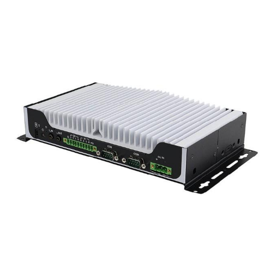
General Information 1.5 Product View Front View Function HDMI DP (supports DP++) DVI-D USB 3.1 @Gen 2 USB 2.0 RJ45 for 2.5 Gigabit LAN Front View SE-603-N User Manual... - Page 12 Rear View Function Power Switch Power Button Line-in / Line-out DIO (4-in/4-out) RS232/422/485 + RS232 DC-in Power Rear View SE-603-N User Manual...
- Page 13 General Information SE-603-N User Manual...
-
Page 14: Dimensions
1.6 Dimensions Unit: mm SE-603-N User Manual... -
Page 15: Hardware Installation & Motherboard Information
Chapter 2 Hardware Installation & Motherboard Information The information provided in this chapter includes: • Installation of memory, M.2 cards and antennas • Information and locations of connectors... -
Page 16: Installation / Replacement
2.1 Installation / Replacement The following pictures show how to disassemble the SE-603-N. Flip the system to expose the bottom cover and remove the six (6) screws as shown in the picture below. Afterwards, you will be able to access the sockets and connectors that will be discussed in the following pages. - Page 17 Hardware Configuration 2.1.1 Memory To install memory modules, locate the memory slot on the motherboard and perform the following steps: SE-603-N User Manual...
- Page 18 2. Gently push the module in an upright position until the clips of the slot close to hold the module in place when the module touches the bottom of the slot. To remove the module, press the ejector tabs outwards with your fingertips to eject the module. SE-603-N User Manual...
- Page 19 Align the key of the M.2 card to the interface, and insert the card slantwise. Fix the M.2 card with an screw. M.2 Slots Description M.2 B-Key [supports USB2.0 & 3.0 & PCIe] M.2 M-Key M.2 E-Key [supports USB2.0 & PCIe] SE-603-N User Manual...
- Page 20 1. Thread and fasten the hex nut and the 2. Apply adhesive around here. washer. Then install the antenna. Info: The diameter of the nut is around 6.35 mm (0.25”-36UNC). SE-603-N User Manual...
-
Page 21: Setting The Jumpers
Hardware Configuration 2.2 Setting the Jumpers Set up and configure the SE-603-N by using jumpers for various settings and features according to the application requirements. Contact your supplier if you have doubts about the best configuration. 1.2.1 How to Set Jumpers Jumpers are short-length conductors consisting of several metal pins with a non-conductive base mounted on the circuit board. -
Page 22: Jumper & Connector Locations On Motherboard
2.3 Jumper & Connector Locations on Motherboard Motherboard: MBD603 MBD603 – top and I/O MBD603 – back and I/O SE-603-N User Manual... - Page 23 2.3.1 Jumper Quick Reference Jumper / Switch Function JP1 / JP2 COM1 / COM2 RI Power AT/ATX Mode Selection Clear ME Clear RTC 2.3.2 JP1 / JP2: COM1 / COM2 RI Power Function Pin closed Illustration Normal (default) SE-603-N User Manual...
- Page 24 2.3.3 JP3: AT/ATX Mode Selection Function Pin closed Open Closed 2.3.4 JP6: Clear ME Function Pin closed Normal (Default) Clear CMOS SE-603-N User Manual...
- Page 25 Hardware Configuration 2.3.5 JP7: Clear RTC Function Pin closed Normal (Default) Clear RTC SE-603-N User Manual...
- Page 26 ESPI Debug Connector M.2 B-Key [supports USB2.0 & 3.0 & PCIe] SPI Flash Connector J10/J15 DDR4 Sockets M.2 E-Key [supports USB2.0 & PCIe] M.2 M-Key iSMART Flash Connector LED1 iSMART LED LED2 HDD LED LED3 Power LED SE-603-N User Manual...
- Page 27 Hardware Configuration 2.3.7 CN1: COM1 Connector (supports RI with 5V/12V) 2.3.8 CN2: COM2 Connector (supports RI with 5V/12V) 2.3.9 CN4: I226 RJ45 Connector SE-603-N User Manual...
- Page 28 2.3.10 CN5: USB2.0 Connector 2.3.11 CN6, CN7, CN8: USB3.1 Connector 2.3.12 CN9: DVI-D Connector SE-603-N User Manual...
- Page 29 Hardware Configuration 2.3.13 CN10: Display++ Connector 2.3.14 CN11: HDMI 2.0 Connector 2.3.15 CN12: SIM Card Slot SE-603-N User Manual...
- Page 30 2.3.16 CN13: DC_IN Connector 12V~24V (+-10%) DC Power input 2.3.17 SW1, J1: Power Button SE-603-N User Manual...
- Page 31 Hardware Configuration 2.3.18 J2: Line_In Jack 2.3.19 J3: Line_Out Jack 2.3.20 J4: Digital IO Connector SE-603-N User Manual...
- Page 32 2.3.21 J5: Front Panel Connector Signal Name Signal Name Power BTN Power BTN HDD LED+ HDD LED- Reset BTN Reset BTN Power LED+ Power LED- 2.3.22 J6: ESPI Debug Connector SE-603-N User Manual...
- Page 33 Hardware Configuration 2.3.23 J8: M.2 B-Key Note: Supports USB2.0 & 3.0 & PCIe (for 4G 5G module) 2.3.24 J9: SPI Flash Connector SE-603-N User Manual...
- Page 34 2.3.25 J10/J15: DDR4 Sockets 2.3.26 J11: M.2 E-Key Note: Supports USB2.0 & PCIe (for wifi module) SE-603-N User Manual...
- Page 35 Hardware Configuration 2.3.27 J13: M.2 M-Key 2.3.28 J14: iSMART Flash Connector 2.3.29 LED1: iSMART LED 2.3.30 LED2: HDD LED 2.3.31 LED3: Power LED SE-603-N User Manual...
-
Page 36: Chapter 3 Driver Installation
Chapter 3 Driver Installation The information provided in this chapter includes: • Intel Chipset Software Installation Utility • VGA Driver Installation • HD Audio Driver Installation • LAN Drivers Installation • Intel ME Drivers Installation • Intel Thunderbolt Drivers Installation... -
Page 37: Introduction
Software Installation Utility before proceeding with drivers installation. ® 3.2 Intel Chipset Software Installation Utility 1. Run the drivers disk. Click Intel on the left pane and then Intel(R) TigerLake-U Chipset Drivers. Click Intel(R) Chipset Software Installation Utility. SE-603-N User Manual... - Page 38 2. When the Welcome screen to the Intel® Chipset Device Software appears, click Next to continue. 3. Accept the software license agreement. 4. On the Readme File Information screen, click Install. 5. After the installation has been completed, press Finish to complete the setup process. SE-603-N User Manual...
-
Page 39: Vga Driver Installation
1. Run the drivers disk. Click Intel on the left pane and then Intel(R) TigerLake-U Chipset Drivers. Click Intel(R) HD Graphics Driver. 2. On the following screen, click Begin Installation. 3. Click I agree to accept the license agreement. SE-603-N User Manual... - Page 40 4. On the next screen, click Start. 5. After the installation has been completed, click Finish. SE-603-N User Manual...
-
Page 41: Hd Audio Driver Installation
1. Run the drivers disk. Click Intel on the left pane and then Intel(R) TigerLake-U Chipset Drivers. Click Realtek High Definition Audio Driver. 2. On the Welcome screen, click Next to continue. 3. When the InstallShield Wizard has successfully installed the Realtek Audio Driver, click Finish to complete setup. SE-603-N User Manual... -
Page 42: Lan Drivers Installation
3.5 LAN Drivers Installation 1. Run the drivers disk. Click Intel on the left pane and then Intel(R) TigerLake-U Chipset Drivers.Click Intel(R) PRO LAN Network Drivers. 2. Choose Install Drivers and Software. SE-603-N User Manual... - Page 43 Connections, click Next. 4. Accept the terms in the license agreement and click Next. 5. In the Setup Options screen, click Next. 6. Click install to begin installation. 7. Click Finish when Install wizard has completed the installation. SE-603-N User Manual...
-
Page 44: Intel® Me Drivers Installation
2. When the welcome screen to the Intel® Management Engine Components appears, click Next. 3. Accept the license agreement and click Next. 4. On the Setup’s Destination Folder screen, click Next. 5. After the components have been completely installed, click Finish. SE-603-N User Manual... -
Page 45: Intel Thunderbolt Drivers Installation
1. Run the drivers disk. Click Intel on the left pane and then Intel(R) TigerLake-U Chipset Drivers. Click Intel(R) Thunderbolt Drivers. 2. Agree to the license terms and conditions and click Install. 3. Restart the computer after installation has been completed. SE-603-N User Manual... -
Page 46: Chapter 4 Bios Setup
Chapter 4 BIOS Setup This chapter describes the different settings available in the AMI BIOS. The topics covered in this chapter are as follows: • Main Settings • Advanced Settings • Chipset Settings • Security Settings • Boot Settings • Save &... -
Page 47: Introduction
These defaults have been carefully chosen by both AMI and the system manufacturer to provide the absolute maximum performance and reliability. Changing the defaults could make the system unstable and crash in some cases. SE-603-N User Manual... -
Page 48: Main Settings
Set the time. System Time Use the <Tab> key to switch between the time elements. 4.4 Advanced Settings This section allows the configuration of the system and the selection of the system features according to your preference. SE-603-N User Manual... - Page 49 Discrete Bluetooth Int. BT interface. Advanced settings Configure ACPI objects for wireless devices WWAN Configuration Configure WWAN related options. Selct the M.2 WWAN Device options to enable 4G – 7360/756) (Intel), 5G – M80 WWAN Device (MediaTek) Modems SE-603-N User Manual...
- Page 50 When enabled, a VMM can utilize the Intel (VMX) Virtualization additional hardware capabilities provided by Technology Vanderpool Technology. Number of cores to enable in each processor Active Processor Cores package. Hyper-Threading Enable/Disable Hyper-Threading Technology. Enable/Disable AES (Advanced Encryption Standard) SE-603-N User Manual...
- Page 51 Technology CPPC v2 interface to allow for hardware controlled P-states Configurable TDP Mode as Norminal / Up / Down / Deactivate TDP selection. Deactivate Configurable TDP Boot option will seet MSR to Nominal and MMIO to Zero. SE-603-N User Manual...
- Page 52 4.4.4 PCH-FW Configuration 4.4.5 Trusted Computing BIOS Setting Description Option: Enable / Disable. OS will not show security Security Device device. TCG EFI protocol and INTIA interface will not be Support available. SE-603-N User Manual...
- Page 53 BIOS Setup 4.4.6 ACPI Settings BIOS Setting Description Enables or Disables System ability to Hibernate (OS/S4 Sleep State). This option Enable Hibernation may not be effective with some operating systems. 4.4.7 iSMART Controller SE-603-N User Manual...
- Page 54 Sets parameters of Serial Port 2 (COMB). Serial Port Enable / Disable the serial port. Select an optimal setting for the Super IO device. Options are: IO=3F8h; IRQ=4; Change Settings IO=3F8h; IRQ=3,4,5,6,7,9,10,11,12; IO=2F8h; IRQ=3,4,5,6,7,9,10,11,12; IO=3E8h; IRQ=3,4,5,6,7,9,10,11,12; IO=2E8h; IRQ=3,4,5,6,7,9,10,11,12; SE-603-N User Manual...
- Page 55 These fields are the parameters of the hardware Temperatures / monitoring function feature of the motherboard. The Voltages values are read-only values as monitored by the system and show the PC health status. 4.4.10 AMI Graphic Output Protocol Policy SE-603-N User Manual...
- Page 56 The maximum time the device will take before it properly reports itself to the Host Controller. “Auto” uses default value for a Root port it is Device power-up delay 100ms. But for a Hub port, the delay is taken from Hub descriptor. SE-603-N User Manual...
- Page 57 BIOS Setup 4.4.12 Network Stack Configuration 4.4.13 NVMe Configuration SE-603-N User Manual...
-
Page 58: Chipset Settings
System Agent (SA) parameters PCH-IO Configuration PCH parameters 4.5.1 System Agent (SA) Configuration BIOS Setting Description Graphics Configuration Configures the graphics settings. VMD setup menu VMD Configuration settings VT-d Checks if VT-d function on MCH is supported. SE-603-N User Manual... - Page 59 Select DVMT 5.0 Pre-Allocated (Fixed) Graphics DVMT Pre-Allocated Memory size used by the internal graphics device Select DVMT 5.0 Total Graphics Memory size DVMT Total Gfx mem used by the internal graphics device 4.5.1.2. VMD setup menu SE-603-N User Manual...
- Page 60 PCH LAN Controller Enables / Disables the onboard NIC. Power-On after Power Specify what state to go to when power is failure reapplied afater a power failure (G3 state) 4.5.2.1. SATA and RST Configuration: 4.5.2.2. USB Configuration: SE-603-N User Manual...
-
Page 61: Security Settings
BIOS Setup 4.6 Security Settings SE-603-N User Manual... - Page 62 Restore Factory Forces system to user mode. Install factory default Keys Secure Boot key databases. Enables expert users to modify Secure Boot Policy Management variables without full authentication. SE-603-N User Manual...
-
Page 63: Boot Settings
Enables / Disables Quiet Boot option. Boot mode Selects a Boot mode, Legacy / UEFI. select Boot Option Sets the system boot order. Priorities UEFI Hard Disk Specifies the Boot Device Priority sequence from Drive BBS available UEFI Hard Disk Drives. Priorities SE-603-N User Manual... -
Page 64: Save & Exit Settings
Saves the changes done so far as User Defaults. Defaults Restore User Restores the user defaults to all the setup options. Defaults Launch EFI Shell Attempts to launch EFI Shell application (Shell.efi) from filesystem from one of the available filesystem devices. device SE-603-N User Manual... -
Page 65: Appendix
Appendix This section provides the mapping addresses of peripheral devices and the sample code of watchdog timer configuration. • I/O Port Address Map • Interrupt Request Lines (IRQ) • Watchdog Timer... -
Page 66: I/O Port Address Map
Programmable interrupt controller 0x0000002C-0x0000002D Programmable interrupt controller 0x00000030-0x00000031 Programmable interrupt controller 0x00000034-0x00000035 Programmable interrupt controller 0x00000038-0x00000039 Programmable interrupt controller 0x0000003C-0x0000003D Programmable interrupt controller 0x000000A0-0x000000A1 Programmable interrupt controller 0x000000A4-0x000000A5 Programmable interrupt controller 0x000000A8-0x000000A9 Programmable interrupt controller 0x000000AC-0x000000AD Programmable interrupt controller SE-603-N User Manual... - Page 67 PCI Express Root Complex 0x00000D00-0x0000FFFF PCI Express Root Complex 0x00000040-0x00000043 System timer 0x00000050-0x00000053 System timer 0x00003000-0x00003FFF Intel(R) PCI Express Root Port #7 - A0BE 0x00002000-0x000020FE Motherboard resources 0x00000060-0x00000060 Standard PS/2 Keyboard 0x00000064-0x00000064 Standard PS/2 Keyboard 0x0000EFA0-0x0000EFBF Intel(R) SMBus - A0A3 SE-603-N User Manual...
-
Page 68: Interrupt Request Lines (Irq)
IRQ 4294967286 Intel(R) I211 Gigabit Network Connection IRQ 4294967285 Intel(R) I211 Gigabit Network Connection IRQ 4294967283 Intel(R) I211 Gigabit Network Connection IRQ 4294967293 PCI Express Root Port IRQ 16 High Definition Audio Controller IRQ 17 USB Synopsys Controller SE-603-N User Manual... -
Page 69: Watchdog Timer
(SIO == 0) printf("Can not detect Fintek 81866, program abort.\n"); return(1); }//if (SIO == 0) if (argc != 2) printf(" Parameter incorrect!!\n"); return (1); bTime = strtol (argv[1], endptr, 10); printf("System will reset after %d seconds\n", bTime); SE-603-N User Manual... - Page 70 Set_ F81804_LD(0x07); //switch to logic device 7 bBuf = Get_ F81804_Reg(0xFA); bBuf &= ~0x01; Set_ F81804_Reg(0xFA, bBuf); //disable WDTO output bBuf = Get_ F81804_Reg(0xF5); bBuf &= ~0x20; bBuf |= 0x40; Set_ F81804_Reg(0xF5, bBuf); //disable WDT //--------------------------------------------------------------------------- SE-603-N User Manual...
- Page 71 (ucDid == 0x07) //Fintek 81866 { goto Init_Finish; F81804_BASE = 0x00; result = F81804_BASE; Init_Finish: return (result); //--------------------------------------------------------------------------- void Unlock_ F81804 (void) outportb( F81804_INDEX_PORT, F81804_UNLOCK); outportb( F81804_INDEX_PORT, F81804_UNLOCK); //--------------------------------------------------------------------------- void Lock_ F81804 (void) outportb( F81804_INDEX_PORT, F81804_LOCK); //--------------------------------------------------------------------------- SE-603-N User Manual...
- Page 72 Set_ F81804_Reg( unsigned char REG, unsigned char DATA) Unlock_ F81804(); outportb( F81804_INDEX_PORT, REG); outportb( F81804_DATA_PORT, DATA); Lock_ F81804(); //--------------------------------------------------------------------------- unsigned char Get_ F81804_Reg(unsigned char REG) unsigned char Result; Unlock_ F81804(); outportb( F81804_INDEX_PORT, REG); Result = inportb( F81804_DATA_PORT); Lock_ F81804(); return Result; //--------------------------------------------------------------------------- SE-603-N User Manual...
- Page 73 #define F81804_REG_LD 0x07 //--------------------------------------------------------------------------- #define F81804_UNLOCK 0x87 #define F81804_LOCK 0xAA //--------------------------------------------------------------------------- unsigned int Init_ F81804(void); void Set_ F81804_LD( unsigned char); void Set_ F81804_Reg( unsigned char, unsigned char); unsigned char Get_ F81804_Reg( unsigned char); //--------------------------------------------------------------------------- #endif // F81804_H SE-603-N User Manual...
Need help?
Do you have a question about the SE-603-N and is the answer not in the manual?
Questions and answers