Table of Contents
Advertisement
Quick Links
Advertisement
Table of Contents

Related Manuals for IBASE Technology SI-304


Summary of Contents for IBASE Technology SI-304
- Page 1 SI-304 User Manual SI-304 User Manual...
- Page 2 SI-304 User Manual Revision Release Date V1.0 2015/07/30...
- Page 3 IBASE Technology Inc. Copyright © 2013 IBASE Technology Inc. All Rights Reserved. No part of this manual, including the products and software described in it, may be reproduced, transmitted, transcribed, stored in a retrieval system, or translated into any language in any form or by any means, except documentation kept by the purchaser for backup purposes, without the express written permission of IBASE Technology INC.
-
Page 4: Table Of Contents
1.2 System Specifications...................... 2 1.2.1 Hardware Specifications ....................2 1.2.2 Dimensions ........................3 1.2.3 I/O View ........................... 4 1.3 Exploded View of the SI-304 Assembly ................4 1.3.1 Parts Description ......................5 1.4 Packing List ........................6 1.4.1 Optional Items module ....................6 1.5 Hardware Installation ....................... -
Page 5: Setting Up Your System
IBASE Technology Inc. Safety Information Your SI-304 is designed and tested to meet the latest standards of safety for information technology equipment. However, to ensure your safety, it is important that you read the following safety instructions Setting up your system ... -
Page 6: Care During Use
SI-304 User Manual Care during use Do not walk on the power cord or allow anything to rest on it. Do not spill water or any other liquids on your system. When the system is turned off, a small amount of electrical current still flows. -
Page 7: Acknowledgments
IBASE Technology Inc. Acknowledgments AMI is a registered trademark of AMI Software International, Inc. AMD and ATI are registered trademarks of AMD Corporation. Intel, Pentium, and Intel Core are registered trademarks or trademarks of Intel Corporation. ... -
Page 9: Chapter 1 Introduction
The “Signature Book™” SI-304 is a professional digital signage system powered by 2nd Gen AMD Embedded R-series APU-based Signage Player with Radeon 9000 series graphics. The SI-304 integrates 4 HDMI ports with EDID emulation function. Additionally, SI-304 has two dual-channel DDR3-2133 sockets to provide up to 32GB of memory. -
Page 10: System Specifications
SI-304 User Manual 1.2 System Specifications 1.2.1 Hardware Specifications Model Name SI-304 System Mainboard MBD304 2nd Gen. R-series QC RX-427BB 2.7/3.4G DC RX-225BB 2.2/3.0G APU Memory 2x DDR3 2133 SO-DIMM, dual channel, Max. 32GB I/O Interface 4x HDMI 2x USB 3.0 ports 1x USB 2.0 port... -
Page 11: Dimensions
IBASE Technology Inc. 1.2.2 Dimensions Copyright © 2013 IBASE Technology Inc. Rights Reserved. -
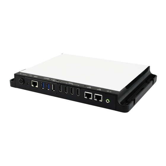
Page 12: I/O View
SI-304 User Manual 1.2.3 I/O View SI-304 front side 1.3 Exploded View of the SI-304 Assembly... -
Page 13: Parts Description
IBASE Technology Inc. 1.3.1 Parts Description Part No. Description Part No. Description SI-304 Main Board Thermal Module System Fan M.2 Module Mini PCI-E Die Casting-Case Cover I/O Plate M.2 Bracket Mounting Screw Copyright © 2013 IBASE Technology Inc. Rights Reserved. -
Page 14: Packing List
SI-304 User Manual 1.4 Packing List Item No. Description Driver CD Power adaptor Power cord 1.4.1 Optional Items module Description WiFi Solution Wireless; PCI-E Mini Card 802.11B/G/N [AW-NE238H] WiFi module (A008WLAWNE238H000P) External Antenna, WiFi Antenna (A055RFA02C2M20800P) 2pcs Internal Antenna 100mm [BTC130-1-70B-100] RoHS... -
Page 15: Hardware Installation
IBASE Technology Inc. 1.5 Hardware Installation 1.5.1 Mounting Installation 1. Please install SI-304 to the intended location using 4x M4*0.7*6L screws, as shown in the picture. Copyright © 2013 IBASE Technology Inc. Rights Reserved. -
Page 16: Chapter 2 Motherboard Introduction
SI-304 User Manual CHAPTER 2 MOTHERBOARD INTRODUCTION 2.1 Introduction MBD304 Jumpers and Connectors... - Page 17 IBASE Technology Inc. MBD304 Board Dimensions Copyright © 2013 IBASE Technology Inc. Rights Reserved.
-
Page 18: Installations
SI-304 User Manual 2.2 Installations 2.2.1 Installing the Memory The MBD304 board supports four DDR3 memory modules for a maximum total of 32GB in DDR3 SODIMM memory type. Installing and Removing Memory Modules To install the DDR3 modules, locate the memory slot on the board and perform the following steps: 1. -
Page 19: Setting The Jumpers
IBASE Technology Inc. 2.3 Setting the Jumpers Jumpers are used on MBD304 to select various settings and features according to your needs and applications. Contact your supplier if you have doubts about the best configuration for your needs. The following lists the jumpers and connectors on MBD304 and their respective functions. - Page 20 SI-304 User Manual J1: Memory Voltage Setting Function 1.5V 1.35V COM1: COM1 Connector COM1 Pin # Signal Name DSR, Data set ready GND, ground GND, ground TXD, Transmit data RXD, Receive data DCD, Data carrier detect DTR, Data terminal ready...
- Page 21 IBASE Technology Inc. CN11: Audio Line out JP2: SPI Flash Connector J8: Half Mini PCIE Slot J8: LPC Debug Port Connector J22: Front Panel Signal Name Pin # Pin # Signal Name Power BTN Power BTN HDD LED+ HDD LED-...
-
Page 22: Chapter 3 Bios Setup
SI-304 User Manual CHAPTER 3 BIOS SETUP This chapter describes the different settings available in the AMI BIOS that comes with the board. The topics covered in this chapter are as follows: 3.1 BIOS Introduction The BIOS (Basic Input/Output System) installed in your computer system’s ROM supports Intel processors. - Page 23 IBASE Technology Inc. Main Settings Aptio Setup Utility – Copyright © 2012 American Megatrends, Inc. Main Advanced Chipset Boot Security Save & Exit Choose the system default language System Date [Tue 01/20/2015] System Time [15:27:20] → ← Select Screen ↑↓ Select Item...
- Page 24 SI-304 User Manual Advanced Settings This section allows you to configure and improve your system and allows you to set up some system features according to your preference. Aptio Setup Utility Advanced Main Chipset Boot Security Save & Exit Launch PXE OpROM Disabled ►...
- Page 25 IBASE Technology Inc. PCI Express Settings Aptio Setup Utility Advanced Main Chipset Boot Security Save & Exit PCI Express Device Register Settings Relaxed Ordering Enabled Extended Tag Disabled No Snoop Enabled Maximum Payload Auto Maximum Read Request Auto → ← Select Screen PCI Express Link Register Settings ↑↓...
- Page 26 SI-304 User Manual Unpopulated Links In order to save power, software will disable unpopulated PCI Express links, if this option set to ‘Disable Link’. Restore PCIE Registers On non-PCI Express aware OS’s (Pre Windows Vista)some devices may not be correctly reinitialized after S3.Enabling this restors PCI Express device configuration on S3 resume...
- Page 27 IBASE Technology Inc. ACPI Settings Aptio Setup Utility Advanced Main Chipset Boot Security Save & Exit ACPI Settings → ← Select Screen ↑↓ Select Item Enter: Select Change Field F1: General Help Enable Hibernation Enabled F2: Previous Values F3: Optimized Default ACPI Sleep State S3 (Suspend to R…)
- Page 28 SI-304 User Manual CPU Configuration This section shows the CPU configuration parameters. Advanced Main Chipset Boot Security Save & Exit CPU Configuration → ← Select Screen Module Version: 4.6.5.4 TrinityPI 026 ↑↓ Select Item Enter: Select Change Field AGESA Version: 1.1.0.7...
- Page 29 IBASE Technology Inc. IDE Configuration Aptio Setup Utility Advanced Main Chipset Boot Security Save & Exit IDE Configuration → ← Select Screen ↑↓ Select Item Enter: Select Change Field SATA Port0 Not Present F1: General Help F2: Previous Values SATA Port1...
- Page 30 SI-304 User Manual iSmart Controller 3.1 Aptio Setup Utility Advanced Main Chipset Boot Security Save & Exit Auto Power On Schedule Power-On after Power failure Enable PWR Resume Delay Disable → ← Select Screen ↑↓ Select Item Temperature Guardian Disable...
- Page 31 IBASE Technology Inc. ASF Configuration Aptio Setup Utility Advanced Main Chipset Boot Security Save & Exit Alert Standard Format (ASF) Configuration ASF Support Disabled → ← Select Screen ↑↓ Select Item ASF BIOS Mode Enter: Select Change Field F1: General Help...
- Page 32 SI-304 User Manual USB Configuration Aptio Setup Utility Advanced Main Chipset Boot Security Save & Exit USB Configuration USB Module Version 8.10.31 USB Devices: 1 Keyboard, 1 Mouse Legacy USB Support Enabled → ← Select Screen XHCI Hand-off Enabled ↑↓ Select Item...
- Page 33 IBASE Technology Inc. F81846 Super IO Configuration Aptio Setup Utility Advanced Main Chipset Boot Security Save & Exit F81866 Super IO Configuration → ← Select Screen ↑↓ Select Item F81866 Super IO Chip F81846 Enter: Select ► Serial Port 0 Configuration...
- Page 34 SI-304 User Manual Chipset Settings This section allows you to configure and improve your system and allows you to set up some system features according to your preference. Aptio Setup Utility Chipset Main Advanced Boot Security Save & Exit → ←...
- Page 35 IBASE Technology Inc. Aptio Setup Utility Chipset Main Advanced Boot Security Save & Exit AMD Reference code Version: Trinity PI 1.1.0.7 Options for SATA Configuration → ← Select Screen ↑↓ Select Item Enter: Select Change Field ► SB SATA Configuration...
- Page 36 SI-304 User Manual Aptio Setup Utility Chipset Main Advanced Boot Security Save & Exit North Bridge Configuration → ← Memory Information Select Screen ↑↓ Select Item Enter: Select Change Field F1: General Help Total memory: 2048 MB (DDR3) F2: Previous Values F3: Optimized Default ►...
- Page 37 IBASE Technology Inc. Boot Settings This section allows you to configure the boot settings. Aptio Setup Utility Boot Main Advanced Chipset Security Save & Exit Boot Configuration Setup Prompt Timeout Bootup NumLock State Quiet Boot Disabled Fast Boot Disabled Boot Mode select...
- Page 38 SI-304 User Manual CSM parameters This section allows you to configure the boot settings. Aptio Setup Utility Boot Main Advanced Chipset Security Save & Exit Launch CSM Always Boot option filter UEFI and Legacy → ← Select Screen Launch PXE OpROM policy Do not launch ↑↓...
- Page 39 IBASE Technology Inc. Security Settings This section allows you to configure and improve your system and allows you to set up some system features according to your preference. Aptio Setup Utility Security Main Advanced Chipset Boot Save & Exit Password Description If ONLY the Administrator’s password is set,...
- Page 40 SI-304 User Manual Save & Exit Settings Save & Exit Main Advanced Chipset Boot Security Save Changes and Exit Discard Changes and Exit Save Changes and Reset Discard Changes and Reset → ← Select Screen Save Options ↑↓ Select Item...
-
Page 41: Chapter 4 Drivers Installation
IBASE Technology Inc. CHAPTER 4 DRIVERS INSTALLATION IMPORTANT NOTE: After installing your Windows operating system, you must install first the Intel Chipset Software Installation Utility before proceeding with the drivers installation. 4.1 VGA Drivers Installation 1. Insert the drivers DVD that comes with the board. Click AMD, then AMD A77E Chipset Drivers. - Page 42 SI-304 User Manual 3. When the welcome screen appears, click Next. 4. Select the language you would like to be displayed and click Next. 5. Click Next to continue the installation process.
- Page 43 IBASE Technology Inc. 6. Select Express and the installation location and click Next. Copyright © 2013 IBASE Technology Inc. Rights Reserved.
-
Page 44: Click Accept To Accept The End User License Agreement
SI-304 User Manual 7. Click Accept to accept the End User License Agreement. 8. To reboot the system, click Yes. -
Page 45: Audio Drivers Installation
IBASE Technology Inc. 4.2 Audio Drivers Installation 1. Insert the drivers DVD that comes with the board. Click AMD, then Realtek High Definition Audio Driver. 2. When the Welcome screen to the InstallShield Wizard appears, click Next. 3. InstallShield Wizard is now complete, click Finish to restart the system and for changes to take effect. -
Page 46: Lan Drivers Installation
SI-304 User Manual 4.3 LAN Drivers Installation 1. Insert the drivers DVD that comes with the board. Click LAN Card. 2. Click Realtek LAN Controller Drivers. 3. Click Realtek RTL8111EP LANDrivers. 4. When the Welcome screen appears, click Next. 5. click Install to begin the installation. -
Page 47: Appendix
IBASE Technology Inc. Appendix A. ATI Eyefinitity setting After finishing AMD VGA driver installation, you can start to use “AMD Catalyst Control Center”. Choose “AMD Eyefinity Multi-Display” for Video wall display configuration setting. Copyright © 2013 IBASE Technology Inc. Rights... - Page 48 SI-304 User Manual Select “Create Eyefinity Display Group”...
- Page 49 IBASE Technology Inc. Select “2 x 2” for the Display configuration Copyright © 2013 IBASE Technology Inc. Rights Reserved.
- Page 50 SI-304 User Manual Make the displays arrangement...
- Page 51 IBASE Technology Inc. Complete the settings Copyright © 2013 IBASE Technology Inc. Rights Reserved.
- Page 52 SI-304 User Manual Now, you can use Screen resolution to check your setting. A screen with 7680 X 4320 is the correct setting for 2 x 2 Display configuration. (Monitor: ASUS PB287Q with 3840 * 2160 resolution support.)
- Page 53 IBASE Technology Inc. Remarks: 3 and 4 Displays configurations Copyright © 2013 IBASE Technology Inc. Rights Reserved.
- Page 54 SI-304 User Manual B. I/O Port Address Map Each peripheral device in the system is assigned a set of I/O port addresses, which also becomes the identity of the device. The following table lists the I/O port addresses used. Address...
-
Page 55: Interrupt Request Lines (Irq)
IBASE Technology Inc. C. Interrupt Request Lines (IRQ) Peripheral devices use interrupt request lines to notify CPU for the service required. The following table shows the IRQ used by the devices on board. Level Function IRQ 0 System timer IRQ 1... -
Page 56: Watchdog Timer Configuration
SI-304 User Manual D. Watchdog Timer Configuration The WDT is used to generate a variety of output signals after a user programmable count. The WDT is suitable for use in the prevention of system lock-up, such as when software becomes trapped in a deadlock. - Page 57 IBASE Technology Inc. if (SIO == 0) printf("Can not detect Fintek 81866, program abort.\n"); return(1); }//if (SIO == 0) if (argc != 2) printf(" Parameter incorrect!!\n"); return (1); bTime = strtol (argv[1], endptr, 10); printf("System will reset after %d seconds\n", bTime);...
- Page 58 SI-304 User Manual Set_F81866_Reg(0xF5, bBuf); //count mode is second Set_F81866_Reg(0xF6, interval); //set timer bBuf = Get_F81866_Reg(0xFA); bBuf |= 0x01; Set_F81866_Reg(0xFA, bBuf); //enable WDTO output bBuf = Get_F81866_Reg(0xF5); bBuf |= 0x20; Set_F81866_Reg(0xF5, bBuf); //start counting //--------------------------------------------------------------------------- void DisableWDT(void) unsigned char bBuf;...
- Page 59 IBASE Technology Inc. //--------------------------------------------------------------------------- // THIS CODE AND INFORMATION IS PROVIDED "AS IS" WITHOUT WARRANTY OF ANY // KIND, EITHER EXPRESSED OR IMPLIED, INCLUDING BUT NOT LIMITED TO THE // IMPLIED WARRANTIES OF MERCHANTABILITY AND/OR FITNESS FOR A PARTICULAR // PURPOSE.
- Page 60 SI-304 User Manual Init_Finish: return (result); //--------------------------------------------------------------------------- void Unlock_F81866 (void) outportb(F81866_INDEX_PORT, F81866_UNLOCK); outportb(F81866_INDEX_PORT, F81866_UNLOCK); //--------------------------------------------------------------------------- void Lock_F81866 (void) outportb(F81866_INDEX_PORT, F81866_LOCK); //--------------------------------------------------------------------------- void Set_F81866_LD( unsigned char LD) Unlock_F81866(); outportb(F81866_INDEX_PORT, F81866_REG_LD); outportb(F81866_DATA_PORT, LD); Lock_F81866(); //--------------------------------------------------------------------------- void Set_F81866_Reg( unsigned char REG, unsigned char DATA) Unlock_F81866();...
- Page 61 IBASE Technology Inc. unsigned char Get_F81866_Reg(unsigned char REG) unsigned char Result; Unlock_F81866(); outportb(F81866_INDEX_PORT, REG); Result = inportb(F81866_DATA_PORT); Lock_F81866(); return Result; //--------------------------------------------------------------------------- //--------------------------------------------------------------------------- // THIS CODE AND INFORMATION IS PROVIDED "AS IS" WITHOUT WARRANTY OF ANY // KIND, EITHER EXPRESSED OR IMPLIED, INCLUDING BUT NOT LIMITED TO THE // IMPLIED WARRANTIES OF MERCHANTABILITY AND/OR FITNESS FOR A PARTICULAR // PURPOSE.
- Page 62 SI-304 User Manual #define F81866_REG_LD 0x07 //--------------------------------------------------------------------------- #define F81866_UNLOCK 0x87 #define F81866_LOCK 0xAA //--------------------------------------------------------------------------- unsigned int Init_F81866(void); void Set_F81866_LD( unsigned char); void Set_F81866_Reg( unsigned char, unsigned char); unsigned char Get_F81866_Reg( unsigned char); //--------------------------------------------------------------------------- #endif //__F81866_H...
Need help?
Do you have a question about the SI-304 and is the answer not in the manual?
Questions and answers