Advertisement
Quick Links
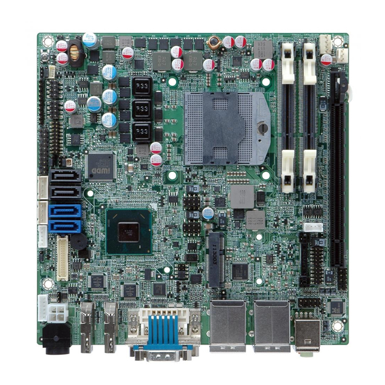
Mini-ITX SBC with Socket G2 for Intel® 22nm Mobile CPU,
DVI-I/Dual HDMI/LVDS, Dual PCIe GbE, USB 3.0, PCIe Mini, SATA
6Gb/s and Audio
Quick Installation Guide
Package Contents
KINO-QM770 package includes the following items:
1 x KINO-QM770 Single Board Computer
2 x SATA with power output cable
1 x RS-232 cable with bracket
1 x I/O shielding
1 x Mini jumper pack
1 x Utility CD
1 x QIG (Quick Installation Guide)
KINO-QM770
Version 1.0
Dec.14, 2015
©2006 Copyright by IEI Integration corp.
All rights reserved.
1
Advertisement

Subscribe to Our Youtube Channel
Related Manuals for IEI Technology KINO-QM770


Summary of Contents for IEI Technology KINO-QM770
- Page 1 KINO-QM770 Quick Installation Guide Version 1.0 Dec.14, 2015 Package Contents KINO-QM770 package includes the following items: 1 x KINO-QM770 Single Board Computer 2 x SATA with power output cable 1 x RS-232 cable with bracket 1 x I/O shielding 1 x Mini jumper pack...
- Page 2 Specifications CPU: Socket G2 for Intel® 3rd generation 22nm mobile processor ® System Chipset: Intel QM77 BIOS: UEFI BIOS System memory: 2 x 204-pins 1066/1333/1600 MHz DDR3 SDRAM SO-DIMM supported (system max. 16GB) Ethernet: ® ® 1 x Intel 82579 PHY (PCIe x1 interface) with Intel AMT 8.0 supported by iEZman software UI 1 x Intel®...
-
Page 3: Ordering Information
Dimensions: 170 mm x 170 mm Weight: GW: 900g; NW: 450g Ordering Information KINO-QM770-R10: Mini-ITX SBC with Socket G2 for Intel® 22nm mobile CPU, DVI-I/dual HDMI/LVDS, dual PCIe GbE, USB 3.0, PCIe Mini, SATA 6Gb/s and Audio 19800-003100-200-RS: Dual ports USB cable with Bracket... -
Page 4: Jumpers Setting
Jumpers Setting LABEL FUNCTION J_CMOS1 CMOS state setting ME_RTC1 ME RTC registers J_ATXCTL1 Select ATX or AT mode J_VLVDS1 LCD Voltage Selector J_PID1 LVDS Panel Resolution Selection J_FLASH1 Flash Descriptor Security Overide Display Selection J_PCIE1 & 2 PCIE Channel Mode Selection(Reserved) J_CMOS1: Clear CMOS Setup J_CMOS1 DESCRIPTION... - Page 5 J_PID1: LVDS Panel Resolution Panel Resolution type select 640 X 480 (18bit) 800 X 480 (18bit) 1024 X 768 (18bit) 1-2 & 3-4 (Default) 1024 X 768 (24bit) 1280 X 800 (24bit) 1-2 & 5-6 1280 X 1024 (48bit) 3-4 & 5-6 1366 X 768 (24bit) 1-2 &...
- Page 6 Table of Connectors LABEL FUNCTION LAN_USB RJ45 LAN and USB 3.0 Connector USB1,USB2 Internal USB 2.0 Connectors KB_MS1 PS/2 MOUSE & KEYBOARD Connector VIDEO1 DVI Connector COM1 External 1 Port Serial Port DB-9 Connectors COM2~3 Internal 2 Serial Port DB-9 Connectors FRONT-PANEL1 Extend Audio Module Connector AUDIO_CV1...
- Page 7 LAN1_USB1/LAN2_USB2: RJ-45 LAN pin define PIN NO. DESCRIPTION PIN NO. DESCRIPTION MD0+ MD2+ MD0- MD2- MD1+ MD3+ MD1- MD3- LAN1_USB1/LAN2_USB2: USB3.0 pin define PIN NO. DESCRIPTION VBUS GND1 STDA_SSRX1_N STDA_SSRX1_P GND_DRAIN STDA_STX1_N STDA_STX1_P USB1, USB2: Internal 4 ports USB Connectors PIN NO.
- Page 8 VIDEO1: DVI-I(Dual Link)+CRT PIN NO. DESCRIPTION PIN NO. DESCRIPTION Data 1+ +5V Power C5-1 Hot Plug Detect Data 2- HPDET Data 2+ Data 0- Data 0+ DDC Clock DDC Data DVI_Clock + Data 1- DVI_Clock - COM1: External Serial Port D-sub Connector (RS-232) PIN NO.
- Page 9 COM3 : Internal Serial Port Connectors (RS-422/485) PIN NO. DESCRIPTION PIN NO. DESCRIPTION RXD485# RXD485+ TXD485+ TXD485# FRONT-PANEL1 : Audio Connector PIN NO. DESCRIPTION PIN NO. DESCRIPTION ANALOG GND LMIC2-L LMIC2-R PRESENCE# LLINE2-R MIC2-JD FRONT-IO LLINE2-L LINE2-JD AUDIO_CV1 : Audio Line-out & MIC-in Connector PIN NO.
- Page 10 IR1: Infrared Interface CN1, CN2 : Serial ATA Power Output Connectors connector PIN NO. DESCRIPTION PIN NO. DESCRIPTION VCC (+5V) +12V IR-RX IR-TX CN5: PCIe Mini Card Slot PIN NO. DESCRIPTION PIN NO. DESCRIPTION PCIE_WAKE# VCC3 1.5V CLKREQ# CLK- CLK+ PCIRST# VCC3 PCIRST#...
- Page 11 INVERTER1: LVDS1 Panel Backlight +12V Power Source connector PIN NO. DESCRIPTION LCD_BKLTCTL +12V BACKLIGHT ENABLE LVDS1: 24-bit dual-channel LVDS Connector PIN NO. DESCRIPTION PIN NO. DESCRIPTION A_Y0 A_Y0# A_Y1 A_Y1# A_Y2 A_Y2# A_CK A_CK# A_Y3 A_Y3# B_Y0 B_Y0# B_Y1 B_Y1# B_Y2 B_Y2# B_CK...
- Page 12 F_PANEL1 : Power button, Rest, HDD & Power LED Indicators Connector PIN NO. DESCRIPTION PWR_BTN+ PWRBTN PWR_BTN- HDD_LED+ HDD_LED- PWR_LED+ Power PWR_LED+ RESET+ RESET PWR1: Adapter DC +12V Main PWR2: Power Supply DC Power Input connector +12V Main power in DESCRIPTION DESCRIPTION +12V...
- Page 13 TPM1 : TPM connector PIN NO. DESCRIPTION PIN NO. DESCRIPTION LCLK LFRAME# LRERST# LAD3 LAD2 LAD1 LAD0 SB3V SERIRQ GLKRUN# LPCPD# LDRQ# BAT1: +3V Battery Connector CN3: SMBus Connector PIN NO. DESCRIPTION PIN NO. DESCRIPTION BAT (+3.3V) SMB_DATA SMB_CLK +V5S JSPI1: Flash BIOS SPI ROM Connector PIN NO.
- Page 14 CN4 : EC debug port PIN NO. DESCRIPTION PIN NO. DESCRIPTION EC_EPP_STB# EC_EPP_AFD# EC_EPP_PD0 EC_EPP_PD1 EC_EPP_INIT# EC_EPP_PD2 EC_EPP_SLIN# EC_EPP_PD3 EC_EPP_PD4 EC_EPP_PD5 EC_EPP_BUSY EC_EPP_PD6 EC_EPP_KSI5 EC_EPP_PD7 EC_EPP_KSI4...
-
Page 15: Board Layout: Jumper And Connector Locations
Board Layout: Jumper and Connector Locations...
Need help?
Do you have a question about the KINO-QM770 and is the answer not in the manual?
Questions and answers