Table of Contents
Advertisement
Quick Links
Amiad Water Systems
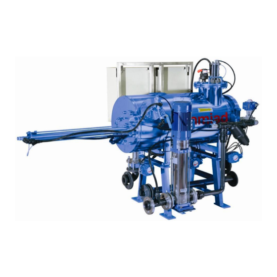
AMF-36K Micro-fiber Filter
With Graphical HMI
Serial number:
Order number:
Catalog number:
Filtration degree:
Tested by:
Installation and Operation
User Guide
_______________
_______________
_______________
_______________
_______________
Instructions
Original Instructions -
Ref. 910101-000592 08.2013
Advertisement
Table of Contents

Subscribe to Our Youtube Channel
Related Manuals for amiad AMF-36K


Summary of Contents for amiad AMF-36K
- Page 1 Amiad Water Systems AMF-36K Micro-fiber Filter With Graphical HMI User Guide _______________ Serial number: _______________ Order number: _______________ Catalog number: _______________ Filtration degree: _______________ Tested by: Installation and Operation Instructions Original Instructions - Ref. 910101-000592 08.2013...
- Page 2 Disclaimer: This document and the information enclosed within it contain restricted and/or privileged information that are intended only for usage by authorized Amiad technicians. If you are not a qualified Amiad technician you must not take nay action in reliance to this document, unless permitted by Amiad.
-
Page 3: Table Of Contents
TABLE OF CONTENTS 1. Introduction & How to use this manual ..................Page 4 1.1 Using this manual 1.2 Safety instructions 1.2.1 General 1.2.2 Installation 1.2.3 Operation, Control and Maintenance 1.2.4 Use of Lifting Equipment 1.2.5 Notes 1.3 General description of the micro-fiber filtration technology 1.3.1 Filter media 1.3.2 Filtration process 1.3.3 The cleaning sequence... -
Page 4: Introduction & How To Use This Manual
Always observe standard safety instructions and good engineering practices whilst working in the filter’s vicinity. Use the filter only for its intended use as designed by Amiad, any misuse of the filter may lead to undesired damage and may affect your warranty coverage. Please consult with Amiad prior to any non-regular use of this equipment. - Page 5 Use only appropriate standard tools and equipment operated by qualified operators when installing, operating and maintaining the filter. When installation is required in hazardous environment sites, underground or high above ground, make sure that the site design and the auxiliary equipment are appropriate and that installation procedures are carried out in accordance with the relevant standards and regulations.
- Page 6 First Operation procedures exactly as described in this manual. Commissioning the filter should be done by an authorized Amiad technician, do not attempt to commission the filter unaccompanied since this may lead to undesired damage and may affect your warranty coverage.
- Page 7 Before disconnecting the filter from the water supply, electricity and pneumatics and before releasing the filter’s residual pressure do NOT: loosen or unscrew bolts remove any protection cover open any service port flange Avoid splashing and water leakage so as to minimize slippage, electrification or damage to the equipment, caused by moisture.
-
Page 8: General Description Of The Micro-Fiber Filtration Technology
General description of the micro-fiber filtration technology Textile fibers are widely used for fine filtration in the disposable cartridge filter market. Amiad Filtration Systems developed an innovative self-cleaning micro-fiber filtration technology and implemented it on a wide range of automatic filters. -
Page 9: Filtration Process
Figure 3 1.3.2 Filtration Process The contaminated liquid flows from the inlet control valve, through the threads, into the grooves and through the nipples to the collector pipe, flowing to the clean liquid chamber and, through the outlet control valve, to the customer’s system (Fig4+5) Figure 4 Figure 5... -
Page 10: The Cleaning Sequence
The cleaning sequence 1.3.3 The control system activates the self cleaning sequence at a preset pressure differential level or by a preset timer, which ever comes first (Fig8) The cleaning sequence starts with the control unit starting the flushing pump , which boosts into the system highly (Fig9) pressurized clean water. - Page 11 Figure 13 Each spray nozzle creates multiple jet streams; these jets pass through the thread layers of the cassette, hit the plastic wall and are forced backwards. This creates a powerful spot back flush, which carries with it the trapped particles and the filter cake out of the cassettes thread layers and through the open drain control valve to the gravity drain system (Fig14, Figure 14...
- Page 12 Once the cleaning of all the cassettes is completed, the flush and the drain control valves are closed and the inlet (Fig20) and the "filter to waste" control valves are opened (Fig21) Figure 20 Figure 21 Raw liquid enters the filter and fills it up and initial filtrate is passed through the "filter to waste" control valve (Fig22) Figure 22 The "filter to waste"...
-
Page 13: Installation
In cases where the pump power supply is not pre connected by the factory, connect the pump to the control panel by means of a cable of 4 x 2.5mm² for a distance of up to 10m. Consult Amiad for cable specifications for distances longer than 10m. -
Page 14: Drainage System
0.5” pipe (or rod) should be prepared at the installation site. This pipe is needed for pushing one of the filter pistons to its start-up position during the commissioning process. Note: - For any further information needed for proper designing of the installation site please contact Amiad’s Engineering Applications Department. -
Page 15: The Installation Process
2.2.1 Positioning the Filter The filter should be positioned and connected according to its Certified Installation Arrangement Drawing. This drawing specifies the layout of the filtration site as prepared by qualified engineers according to Amiad’s Application Engineering Department specifications. Please study your Certified Installation Arrangement Drawings and then position the filter and mount it to the floor area according to the drawings, please take extra care and exercise the relevant safety instructions. - Page 16 Figure 25...
- Page 17 AMF² 36K + HMI 08.2013 Page 17 of 71...
-
Page 18: Pipeline Connections
2.2.2 Pipeline connections After the filter is positioned and secured to its designated location consult your Certified Installation Arrangement Drawings and connect the filter to the pipeline network. In general the filter should be connected to the following points: Upstream pipe –... - Page 19 Disconnect the Proximity Switches SW1 and SW2 from the Piston House Assembly by unscrewing the sensors from their Mounting block. Important note: Make sure that the Mounting Blocks stay at their current position! Any movement of a block will affect the piston’s calibration and will cause damage to the filter. Only the sensors should be removed!!! Remove this sensor only Do not move this...
- Page 20 Unscrew the filter’s Intermediate Cover bolts and open the Cover by gently pulling it out together with the Piston Hosing. AMF² 36K + HMI 08.2013 Page 20 of 71...
- Page 21 Make sure that the V-Shape Plate of the cartridge points to the central line of the filter, if necessary turn it by hand accordingly . Remove Piston#40 by pulling it straightly but gently out of the filter. Make sure not to damage the cassettes by letting the spray nuzzles to hit the cartridge while pulling the piston (you may need assistants to keep the piston balanced while pulling it out of the filter).
- Page 22 Make sure that the filter is disconnected from any electrical power source; carefully open the control panel cabinet and re-tight the bolts of the terminal strips. Re-tight the screws of the terminal strips Piston and Piston Housing re-assembly: Check that the V-Shape Plate of the cartridge points to the central line of the filter, if necessary turns it by hand accordingly.
- Page 23 AMF² 36K + HMI 08.2013 Page 23 of 71...
- Page 24 Gently Push Piston#40 into the filter till it slightly sticks out of the filter housing. Insert the Piston Housing and the filter’s Intermediate Cover over Piston#40. Then re-screw the Cover bolts. Make sure that these three components are aligned verify that the Cover’s O-ring is in place. AMF²...
- Page 25 Re-connect the Proximity Switches SW1 and SW2 to the Piston House Assembly by screwing the sensors to their Mounting blocks. Reconnect this sensor only Do not move this Block! Block Don’t Move this Note: Do not change the position of the mounting blocks! It was calibrated in the factory. AMF²...
- Page 26 5. Re-connect the High Pressure pipe to the far end of the Piston House Assembly. Make sure that Piston #40 is pushed out of the cartridge to ensure that the spray nozzles are not within the cassette package limits: Remove the plug from the piston inlet located at the left side of the cartridge cover. Insert a clean and straight 4.5 meter 0.5”...
-
Page 27: Power Supply- Electricity And Pneumatics
The filter’s Power and Compress Air connections are described in a set of certified drawings prepared for your filtration site requirements according to Amiad’s Application Engineering Department specifications. Please ask your qualified electrician to connect the appropriate protection devices and the electrical cables to the control unit of the filter. - Page 28 The Control Panel The PLC Cabinet The Solenoids Cabinet Main Power Supply Compressed air Connection terminal Connection terminal AMF² 36K + HMI 08.2013 Page 28 of 71...
-
Page 29: Description Of The Control Panel
3. Description of the control panel Introduction Amiad’s AMF 36K filter automatic operation is carried out and controlled by a control panel. The control panel consists of electrical, electronic and pneumatic components integrated and installed in the control-panel’s enclosure that is mounted to the filter housing at an easy to access point. -
Page 30: Internal Components Of The Control Panel
The rest of the control panel components that are not related to the user interface are mounted inside the control- panel’s enclosure according to the IP65 standard. Accesses to these components is allowed only to qualified by Amiad technicians who are familiar with Amiad’s “AMF-control panel description.DOC” and other Amiad technicians’ text books. -
Page 31: Basic Operation Of The Plc
The HMI panel – This component serves as a user interface device connecting between the internal PLC software and the user and allowing data exchange between the PLC and the user. Amiad provides several HMI panels to be connected to the Siemens PLC; the selection of the appropriate panel depends on the specific filter, project or site requirements. - Page 32 While operating the unit it is important to be aware of the following general issues: Unintentional actions - Unwanted actions may be triggered if the operator unintentionally touches several graphic elements (keys) at once. Never press more than one element at a time. ...
- Page 33 Your Administrator user name is: _____________ Your Administrator password is: ______________ Notes: 1. Please contact your Amiad representative for Administrator login details 2. Attempt to change an unauthorized parameter within the system opens the login screen AMF² 36K + HMI 08.2013...
- Page 34 3.5 HMI operation principles The HMI operation is based on the following main components: Menu bar – The menu bar appears across the upper border of the screen and is consist of rectangular keys. Some of these keys can perform a single operation, while the other keys when pressed open a vertical menu-list that contains other single operation keys.
- Page 35 Press here to zoom-in Tables Screens – Screens containing a table showing alphanumeric data on various filter components, system messages or operation parameters. Some of these screens are for showing information only while other tables screens are for data entry (depends on a specific login authorization). Please note: Black color data items are for your information only while Blue color data items showing parameters to be adjusted by the system’s Supervisors and Administrators.
- Page 36 Press this To get this Press this To get this Press this To get this AMF² 36K + HMI 08.2013 Page 36 of 71...
- Page 37 3.6 Finding your way within the system There are several ways to move about the system and the user may even combine between them to his convenience: Using the single operation keys: There are three single operation keys: The Login key – Pressing this key at any time or from any screen moves the system back to the login screen. The user may use this key in order to return to the entry point of the system or for switching between user types (User, Supervisor or Administrator).
- Page 38 3.7 Changing the HMI language One of the HMI features is its multilingual ability; the user can change the interface language on-the-fly by selecting the required language at the Tools / Language Menu. The language changing screen displays national flags of the countries whose languages are available at the HMI system, in order to change the language the user have to select the appropriate flag at this screen.
- Page 39 3.8 HMI screens description This chapter describes in detail the HMI screens divided into their categories: 3.8.1 Login screens The Entry screen of the system – appears when power is applied to the system. This screen allows the user to: Select the user type: Press [User] to login as a regular user Press [Supervisor] to display the supervisor and the administrator...
- Page 40 3.8.2 Graphical screens Main Screen - Front This screen presents: The status of the system – in the upper yellow box. The current DP reading – in the right yellow box The time to next flush - in the lower yellow box The filter drawing shows the status of the various elements of the filter such as valves, piston, etc.
- Page 41 Board Screen This screen presents: The electrical board of the system. The lamps on this screen change color according to the actual status of the filter. Please note that in some HMI versions the Start Cycle button is not active. In such case use the physical Start Cycle button on the actual electrical board of the system.
- Page 42 Valves Screen This screen presents: A detailed valves drawing that shows the following: Text boxes: The current flushing step (during flushing). The labels of the operating valves. The time left till the end of the current flushing step. Graphical elements: The status of the valves together with a direction arrow (green = operated black= not operated) Pump Screen...
- Page 43 3.8.3 Status screens System Status Screen This screen presents the System Status Table: Status – The general status of the system: Idle, Pause, Filtering, Back-flushing, Fault, Attention, Alarm, Delay, etc. DP - The current Differential Pressure reading Inlet Pressure - The current Inlet Pressure reading Outlet Pressure - The current Outlet Pressure reading Time to next Flush - Time to the next timed flush cycle.
- Page 44 Technical Data Screen This screen presents: Flushing Filter – The number of the flushing filter (1 in a single filter installation) Current stroke Number - The current flushing stroke number (1- Operating Pump – The number of the operating pump (Pump1 in a single filter installation) Switches Status –...
- Page 45 Flushing History Screen This screen presents: A report of the last 3 flush cycles. The Stroke column displays the number of strokes performed at each one of the last 3 flush cycles. The Time column displays the total flush time of each one of the last 3 flush cycles.
- Page 46 3.8.4 Program screens Set points Screen This screen allows the operator to set the: Time interval - Set the maximum elapse time between flush cycles. It is recommended that flush cycle will take place at least once every 24 hours [1440 min.]. Enter 9999 for disabling this option.
- Page 47 3.8.5 Tools screens Language Screen This screen allows the operator to: Select the desired HMI language. Press the desired national flag and press OK. Note: please refer to chapter 2.5 Changing the HMI language for a complete explanation on the multilingual feature of the HMI system.
- Page 48 Valves 2 Screen This screen allows the operator to set the: Inlet Valve Opening Delay – Set the delay for opening the inlet valve of the filter. (Default value - 10 seconds.) Filtering to Waste Duration – Set the required time for the “filtering to waste”...
- Page 49 Configuration Screen – Page 1 This screen allows the operator to set: Type of Analog Input A. – The PLC has 2 analog inputs A & B. This parameter set the task of Analog Input A. It can be a DP meter or Outlet pressure meter.
- Page 50 Configuration Screen – Page 2 This screen allows the operator to set: Continue Filtering During Fault – This parameter sets the filter behavior during fault mode. The user can select to continue the filtering during fault or to stop the filtration by closing the inlet and outlet valves of the filter.
- Page 51 Setup Screen – Page 2 This screen allows the operator to set: Filter-to-waste After Pause / Idle – This parameter is used to set the number of filters on which a “Filtering to waste” operation should be performed whenever the system exits a Pause or Idle mode.
- Page 52 3.9 List of system messages This chapter lists the system messages divided into their categories: The following table lists and describes the possible system alarms and attentions messages that may appear on the HMI status screens. Alarm Attention Message Text Remarks √...
- Page 53 √ Filter 1 Index Backward Alarm #44 The Index piston is not unlocked after a forward command. The controller performs a second trial to push the piston and during this trial this alarm message is displayed. √ Filter 1 Index Forward Att. #45 The Index piston is not locked after a backward command.
-
Page 54: Start-Up And First Operation
Operation procedures exactly as described in this section. Please read carefully the following instructions prior to any attempt to operate the filter. Commissioning the filter should be done by an authorized Amiad technician, do not attempt to commission the filter unaccompanied. ... - Page 55 4.1.2 Make sure that the flushing pump SELECTOR SWITCH is in off position. Switch on the power by turning on the MAIN POWER SWITCH. Make sure that the POWER ON LAMP and the controller’s PANEL are lighted up. 4.1.3 Verify that magnetic switch SW1 led is on. This indicates that the main piston is in the right position.
- Page 56 4.1.4 Valves connection verification: A. Opened B. Closed This stage ensures that each one of the filter’s valves is connected correctly to the filter’s control system. Note: The filter’s valves are double action pneumatic valves. Their opening status is indicated by a position indicator which is a red arrow marker located on the valve’s actuator (See pictures A, B for reference).
- Page 57 4.1.5 Valves operation verification: This stage ensures that each one of the filter’s valves functions correctly. Note: This stage requires two persons to complete, a technician at the solenoids cabinet and an assistant near the valves. Use a screwdriver to push-in the manual override-handle of each one of the valves’...
-
Page 58: Wet Stage A. - Initial Flushing Cycle
Wet stage A. – Initial flushing cycle Important notes: During this stage of the filter’s start-up the filter remains isolated from the process water. The supply line for the following procedures is the flushing water supply line which is the source of clean water used for the filter’s cleaning cycles. - Page 59 4.2.2.1 Index motion speed calibration: Please note: The Index piston speed is pre-calibrated in the factory and only in rare occasions there is a need to recalibrate it. In any case consult your dealer before changing this setting. 4.2.3 Step by step flushing: General description: A special step by step operation mode is provided at the filter’s control panel to be used during the filter’s start up...
- Page 60 Actions to be done during the step by step operation: Start the step by step process as described in the general section of this paragraph and run through the process from start to end. Monitor the progress of each step closely and verify that it starts and stops correctly.
-
Page 61: Wet Stage B. - First Filtration Cycle
Wet stage B. – First filtration cycle Important notes: In this stage the filter’s starts the actual filtration of the process water. The following checklist lists the actions and the order of the tasks to be done during wet stage B. √... -
Page 62: Technical Specifications
5. Technical Specifications Standard AMF 36K Specifications Technical Specifications: Filtration Degree 3,7,10,20 micron Flange connections 2” Inlet/Outlet, 2” Drain PN10 Maximum Working Pressure 10 bar Design Pressure 10 bar Maximum Working Temperature 40 degree C Filtration Area 35600 cm2 Filtration Element 350 Cassette Units Inlet/ Outlet Valves 2”... - Page 63 Installation Requirements: Pump Electrical Supply Maximum 4 3 phase/220-400 volt/ 50 Hz or 240-460 volt/60 Hz, other 3 phase supplies by request Control Electrical Supply Maximum 1 phase/ 100 - 240 volt/ 50 or 60 Hz 0.5 Kw Compressed Air Supply 6 bar, dry and lubricated Drainage Facilities Gravity Flow 0.6 m3/cycle of 36 counts...
-
Page 64: Solenoids' Drawing
Solenoids’ drawing AIR PRESSURE INLET MIN. 6 BAR SV 3 SV 8 SV 6 SV 7 SV 5 SV 2 SV 1 SV 4 8 mm 6 mm 8 mm 6 mm 6 mm 6 mm 6 mm 6 mm EXHAUST PARTITION PILOT CHECK... -
Page 65: Control Cabinet Drawings
Control cabinet drawings: AMF² 36K + HMI 08.2013 Page 65 of 71... - Page 66 AMF² 36K + HMI 08.2013 Page 66 of 71...
- Page 67 AMF² 36K + HMI 08.2013 Page 67 of 71...
- Page 68 AMF² 36K + HMI 08.2013 Page 68 of 71...
- Page 69 AMF² 36K + HMI 08.2013 Page 69 of 71...
- Page 70 AMF² 36K + HMI 08.2013 Page 70 of 71...
- Page 71 – to Amiad, at Amiad's cost. If the customer ships any such Product, Amiad suggests the customer package it securely and insure it for value, as Amiad assumes no liability for any loss or damage occurring during shipment. Provided however that in the event Amiad determines that the warranty does not apply to such Product, Distributor shall promptly reimburse Amiad for such cost (including freight and customs).
Need help?
Do you have a question about the AMF-36K and is the answer not in the manual?
Questions and answers