Table of Contents
Advertisement
Quick Links
Advertisement
Table of Contents

Related Manuals for amiad AMF-370K-S


Summary of Contents for amiad AMF-370K-S
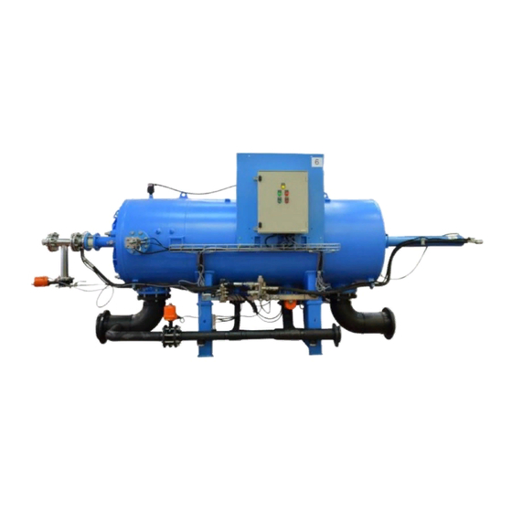
- Page 1 Amiad Water Systems Ltd. AMF-370K - S User Guide Serial number: _______________ Order number: _______________ Catalog number: _______________ Filtration degree: _______________ Tested by: _______________ Installation and Operation Instructions Original Instructions – Ref: 02.2018...
- Page 2 Amiad assumes that all users understand risks involved within this file and/or its attached materials. This document is given in good faith and is not intended to impose any obligation to Amiad. While every effort has been made to ensure the information in this manual is accurate and complete, we would appreciate if you can bring any errors or omissions to the knowledge of Amiad or consult Amiad experts or its authorized representatives if you have any questions.
-
Page 3: Table Of Contents
5.2. Control cabinet drawings ......................68 6. Maintenance Instructions ........................83 6.1. Daily and weekly maintenance..................... 83 6.2. Annual maintenance ........................83 6.3. Parts schedule and drawings ......................84 7. AMIAD LIMITED WARRANTY ....................... 85 AMF 370K -S 02.2018 Page 3 of 86... -
Page 4: Introduction & How To Use This Manual
Always observe standard safety instructions and good engineering practices whilst working in the filter’s vicinity. Use the filter only for its intended use as designed by Amiad, any misuse of the filter may lead to undesired damage and may affect your warranty coverage. - Page 5 Commissioning the filter should be done by an authorized Amiad technician, do not attempt to commission the filter unaccompanied since this may lead to undesired damage and may affect your warranty coverage.
- Page 6 1.2.4 Maintenance Before any maintenance or non-regular operation please read the following: Servicing the filter should be done only by technicians authorized by Amiad. Disconnect the filter from the power supply and lock the Main Power Switch. Disconnect the compressed air supply, release the residual pressure and lock the Pneumatics Main Valve.
-
Page 7: General Description Of The Micro-Fiber Filtration Technology
1.3. General description of the micro-fiber filtration technology Textile fibers are widely used for fine filtration in the disposable cartridge filter market. Amiad Filtration Systems developed an innovative self-cleaning micro-fiber filtration technology and implemented it on a wide range of automatic filters. - Page 8 Figure 3 1.3.2 Filtration Process The contaminated liquid flows from the inlet control valve, through the threads, into the grooves and through the nipples to the collector pipe, flowing to the clean liquid chamber and, through the outlet control valve, to the customer’s system (Fig4+5) Figure 4 Figure 5...
- Page 9 The cleaning sequence 1.3.3 The control system activates the self cleaning sequence at a preset pressure differential level or by a preset timer, whichever comes first (Fig8) The cleaning sequence starts with the control unit starting the flushing pump , which boosts into the system highly (Fig9) pressurized clean water.
- Page 10 Figure 13 Each spray nozzle creates multiple jet streams; these jets pass through the thread layers of the cassette, hit the plastic wall and are forced backwards. This creates a powerful spot back flush, which carries with it the trapped particles and the filter cake out of the cassettes thread layers and through the open drain control valve to the gravity drain system (Fig14, Figure 14...
- Page 11 Once the cleaning of all the cassettes is completed, the flush and the drain control valves are closed and the inlet (Fig20) and the "filter to waste" control valves are opened (Fig21) Figure 20 Figure 21 Raw liquid enters the filter and fills it up and initial filtrate is passed through the "filter to waste" control valve (Fig22) Figure 22 The "filter to waste"...
-
Page 12: Installation
In cases where the pump power supply is not pre connected by the factory, connect the pump to the control panel by means of a cable of 4 x 2.5mm² for a distance of up to 10m. Consult Amiad for cable specifications for distances longer than 10m. - Page 13 0.5” pipe (or rod) should be prepared at the installation site. This pipe is needed for pushing one of the filter pistons to its start-up position during the commissioning process. Note: - For any further information needed for proper designing of the installation site please contact Amiad’s Engineering Applications Department.
-
Page 14: The Installation Process
2.2. The Installation Process 2.2.1 Post shipment inspection Before installing the filter it is necessary to inspect and verify that no damage had occurred during the shipment to the installation site. Please perform the following procedures: This task should be done by a competent technician according to the following instructions, do not attempt to commission the filter unaccompanied. - Page 15 2. Remove Piston#100 by pulling it straightly and firmly out of the filter. Remove the plastic bag with the seal. Remove the Plastic bag 3. Unscrew the filter’s cover long bolt but for safety reasons do not remove its nut! AMF 370K -S 02.2018 Page 15 of 86...
- Page 16 4. Unscrew and remove the hexagon nuts from the filter’s Cover bolts. Do not remove the long bolt nut! 5. Unscrew and remove the two centralizing square nuts from the filter’s Cover bolts. 6. Open the cover by pulling it and carefully, leave it to hang on the long bolt. Do not remove the long bolt’s nut! AMF 370K -S 02.2018 Page 16 of 86...
- Page 17 7. In preparation for removing the #76 piston turn the cartridges plastic covers an align them as depicted in the following pictures. 8. Remove Piston#76 by pulling it straightly but gently out of the filter. Make sure not to damage the cassettes by letting the spray nuzzles to hit the cartridges while pulling the piston (you may need assistants to keep the piston balanced while pulling it out).
- Page 18 9. Using a flashlight inspect the interior of the filter and remove any foreign objects that may entered the filter housing during shipment. Inspect the cartridges and in case that loosen or fallen cassettes are found do not proceed with the installation and contact your supplier immediately. Piston assembly: 1.
- Page 19 iii. Bearing Slide 3. Gently Push Piston#76 into the filter so it will not stick out of the filter housing. 4. Close filter’s Cover and re-screw first the centralizing square nuts, this makes sure that the cover is correctly seated in place. AMF 370K -S 02.2018 Page 19 of 86...
- Page 20 5. Re-screw the Cove's hexagon nuts. 6. Perform the following visual check and verify that all the 35 cassette rows in all cartridges are aligned: Remark: This procedure should be done after each time the cartridge is inserted into the filter and before the initial startup.
- Page 21 Inspect and re-tight all bolts: Visually inspect the filter for loosen bolts, especially verify and re-tight the bolts of the entire filter covers. Make sure that the filter is disconnected from any electrical power source; carefully open the control panel cabinet and re-tight the bolts of the terminal strips.
- Page 22 2.2.2 Separately supplied additional filter parts assembly Due to packing and shipping restrictions some of the filter parts are disconnected in the factory from the filter and packed separately after finalizing the quality control procedures and the factory complete test-run of the filter. These parts should be re-connected to the filter at this stage of the installation process.
- Page 23 3. Insert the Piston House Assembly and screw its bolts firmly. 4. Connect the High Pressure pipe to the far end of the Piston House Assembly and secure it by connecting its U- shape support to the piston housing. 5. Connect the control tube to the Piston House Assembly. AMF 370K -S 02.2018 Page 23 of 86...
- Page 24 2.2.3 Positioning the Filter The filter should be positioned and connected according to its Certified Installation Arrangement Drawing. This drawing specifies the layout of the filtration site as prepared by qualified engineers according to Amiad’s Application Engineering Department specifications. Please study your Certified Installation Arrangement Drawings and then position the filter and mount it to the floor area according to the drawings, please take extra care and exercise the relevant safety instructions.
- Page 25 DRW. REV.: APPROVED 26/09/2016 Typ.2 070002-000077 Confidential property informatio n. Various Amiad Water Systems Ltd. Dim. in mm [inch] DRW. NO: WEIGHT: Reserves the rights to make chan ges. 070002-000077 * Approx. length required for maintenance. All copy rights reserved to Amiad Water Systems Ltd.
- Page 26 APPROVED itai.z MATERIAL: CAT. NO: 26/09/2016 070002-000077 Confidential property informatio n. Various Amiad Water Systems Ltd. DRW. NO: WEIGHT: 1691 KG Reserves the rights to make chan ges. 070002-000077 All copy rights reserved to Amiad Water Systems Ltd. SCALE: 1:20...
- Page 27 The filter’s Power and if applicable its Compress Air connections are described in a set of certified drawings prepared for your filtration site by Amiad’s Application Engineering Department according to the required specifications. Please study these drawings and then ask your qualified electrician to connect the appropriate protection devices and the electrical cables to the control unit of the filter.
- Page 28 The Sub-Master Control Panel The Slave Control Panel Main Power Supply Communication Connection terminal Connection terminal AMF 370K -S 02.2018 Page 28 of 86...
-
Page 29: Description Of The Control Panel
3. Description of the control panel 3.1. Introduction Amiad’s AMF 370K-S filter automatic operation is carried out and controlled by a control panel. The control panel consists of electrical, electronic and when applicable pneumatic components. All these components are integrated and installed in the control-panel’s enclosure that is mounted to the filter housing at an easy to access position. - Page 30 AMF 370K -S 02.2018 Page 30 of 86...
-
Page 31: Basic Operation Of The Plc
2. The HMI panel – This component serves as a user interface device connecting between the internal PLC software and the user and allowing data exchange between the PLC and the user. Amiad provides several HMI panels to be connected to the Siemens PLC; the selection of the appropriate panel depends on the specific filter, project or site requirements. - Page 32 While operating the unit it is important to be aware of the following general issues: Unintentional actions - Unwanted actions may be triggered if the operator unintentionally touches several graphic elements (keys) at once. Never press more than one element at a time. ...
- Page 33 Your Administrator user name is: _____________ Your Administrator password is: ______________ Notes: 1. Please contact your Amiad representative for Administrator login details 2. Attempt to change an unauthorized parameter within the system opens the login screen AMF 370K -S 02.2018...
-
Page 34: Hmi Operation Principles
3.5. HMI operation principles The HMI operation is based on the following main components: Menu bar – The menu bar appears across the upper border of the screen and is consist of rectangular keys. Some of these keys can perform a single operation, while the other keys when pressed open a vertical menu-list that contains other single operation keys. - Page 35 Press here (1) to zoom-in (2) Tables Screens – Screens containing a table showing alphanumeric data on various filter components, system messages or operation parameters. Some of these screens are for showing information only while other tables screens are for data entry (depends on a specific login authorization). Please note: Black color data items are for your information only while Blue color data items showing parameters to be adjusted by the system’s Supervisors and Administrators.
- Page 36 Press this To get this Press this To get this Press this To get this AMF 370K -S 02.2018 Page 36 of 86...
-
Page 37: Finding Your Way Within The System
3.6. Finding your way within the system There are several ways to move about the system and the user may even combine between them to his convenience: Using the single operation keys: There are three single operation keys: The Login key – Pressing this key at any time or from any screen moves the system back to the login screen. The user may use this key in order to return to the entry point of the system or for switching between user types (User, Supervisor or Administrator). -
Page 38: Changing The Hmi Language
3.7. Changing the HMI language One of the HMI features is its multilingual ability; the user can change the interface language on-the-fly by selecting the required language at the Tools / Language Menu. The language changing screen displays national flags of the countries whose languages are available at the HMI system, in order to change the language the user have to select the appropriate flag at this screen. -
Page 39: Hmi Screens Description
3.8. HMI screens description This chapter describes in detail the HMI screens divided into their categories: 3.8.1 Login screens The Entry screen of the system – appears when power is applied to the system. This screen allows the user to: Select the user type: Press [User] to login as a regular user Press [Supervisor] to display the supervisor and the administrator... - Page 40 3.8.2.1 Graphical screens - System Main Screen - System (Home) This screen presents: The status of the system – in the upper middle box. Adjacent to the status box the control panel ID is shown (AMF²- 370K). The time to next flush - in the upper left box. The current DP reading –...
- Page 41 The Menu List Screens - General The General Section screens - Screens list menu This screen shows the opened "screens menu list" of the system's general section. The options are: Pump screen AMF screens The General Section screens - Status menu This screen shows the opened "status menu list"...
- Page 42 The General Section screens - Tools menu This screen shows the opened "Tools menu list" of the system's general section. The options are: Operations screen Filters screen Configuration screen Setup screen Language select screen Time/Date screen The Menu List Screens - Screens Pump Screen This screen presents the two pumps with the...
- Page 43 The System Status Screens System Status Screen This screen presents the System Status Table: Status – The general status of the system: Idle, Pause, Filtering, Back-flushing, Fault, Attention, Alarm, Delay, etc. DP - The current Differential Pressure reading Back Flush Pressure - the current reading of the flush line pressure.
- Page 44 Trends Screen This screen presents 3 optional trends: The DP trend (The blue line and the left Y axis) The Inlet pressure (The red line and right Y axis) The Outlet pressure (The green line and the right Y axis) The Zoom Keys allow the user to set the span of the trends window.
- Page 45 The Program screens Basic Flushing Set points Screen This screen allows the operator to set the: Time interval - Set the maximum elapse time between flush cycles. It is recommended that flush cycle will take place at least once every 24 hours [1440 min.].
- Page 46 Valves 2 Screen This screen allows the operator to set the: Filtering to Waste Duration – Set the required time for the “filtering to waste” stage (V7). (Default value - 55 seconds.) Outlet Valve Opening Delay – Set the delay for opening the outlet valve of the filter.
- Page 47 The Tools screens Operations Screen This screen allows the operator to: AMF Cycles for M303 Flushing – the number of AMF² filter flush cycles for flushing the M303 filter. M303 Flush Counter - The flush counter of the M303 filter - Press the Reset button to reset this counter to zero.
- Page 48 Configuration Screen This screen allows the operator to set: AMF DP Type – Set the type of the system's DP. The options are In-Out (calculated), Analog or Digital. Inlet Pressure Analog High range (20ma) – This parameter sets the maximum range of the Inlet Pressure Meter.
- Page 49 Filter Setup Screen This screen allows the operator to set: Filter Type – This filed must be AMF 370K. Number of Piston Steps – The user may set the number of piston strokes per flushing cycle. For normal operation of the filter this parameter must be Disable Mode Operation –...
- Page 50 Time/Date Screen This screen allows the operator to set the system time: There are two clocks in the system: the PLC clock and the HMI clock. The PLC clock has a backup battery and therefore it remains accurate after a power failure.
- Page 51 3.8.2.2 Graphical screens - Filter Main Screen - Front - Enter to this screen from the system's Home Screen This screen presents: The status of the filter – in the upper middle box. The current DP reading – in the upper right yellow box The time to next flush - in the upper left yellow box The status of valves V2, V3 and V5 The filter drawing shows the status of the various elements of...
- Page 52 The Index This screen presents: A detailed drawing of the two index units that shows the following: SW3 & WS4 status (green or white according to the actual position of the index) SW5 & WS6 status (green or white according to the actual position of the index) The movement of the index during flushing together with the stroke number.
- Page 53 AMF Valves Manual Operation Screen Valve Mode: - Select the desired operation mode. The options are: Automatic or Manual. The screen presents the 7 valves of the filter. In manual operation mode each valve can be set to OFF, OPEN or CLOSE position. A green circle near the valve shows its current operation mode.
- Page 54 3.8.4 System Messages Screen System Messages Screen This screen presents: System Faults – When the system has no faults "No Fault" is displayed. In case of more than one fault message, the display alternates the existing fault messages once at every 3 seconds. System Alarms –...
-
Page 55: List Of System Messages
3.9. List of system messages This chapter lists the system messages divided into their categories: The following table lists and describes the possible system alarms and attentions messages that may appear on the HMI status screens. Alarm Attention Message Text Remarks √... - Page 56 √ Filter 1 Piston SW1 to SW2 Att. #42 The main piston started to move from SW2 to SW1 but the movement is not completed. This is a system alarm message that is issued during the second trial to push the piston by the filter’s controller.
-
Page 57: Start-Up And First Operation
Operation procedures exactly as described in this section. Please read carefully the following instructions prior to any attempt to operate the filter. Commissioning the filter should be done by an authorized Amiad technician, do not attempt to commission the filter unaccompanied. ... - Page 58 4.1.2 Make sure that the flushing pump SELECTOR SWITCH at the master control board is in off position. Switch on the power at the master and slave control boards by turning on the MAIN POWER SWITCHs. Make sure that the POWER ON LAMP and the controller’s PANEL are lighted up.
- Page 59 4.1.3 Verify that magnetic switch SW1 led is on. This indicates that the main piston is in the right position. Return the plug to its place on the 3” flange to and tighten it firmly. If SW1 led is not ON do not proceed and contact your supplier immediately!!! AMF 370K -S 02.2018...
- Page 60 4.1.4 Valves connection verification: Closed This stage ensures that each one of the filter’s valves is connected correctly to the filter’s control system. Note: The filter’s valves are double action electrical valves. Their opening status is indicated by a position indicator which displays the words OPEN or CLOSED according to the actual valve status.
- Page 61 4.1.6 Flushing Pump rotational direction check: This stage ensures that the flushing pump rotates in the These pictures are for demonstrating the required correct direction. process only. Note: This stage requires two persons to complete, a technician at the master control cabinet and an assistant near the pump.
-
Page 62: Wet Stage A. - Initial Flushing Cycle
4.2. Wet stage A. – Initial flushing cycle Important notes: During this stage of the filter’s start-up the filter remains isolated from the process water. The supply line for the following procedures is the flushing water supply line which is the source of clean water used for the filter’s cleaning cycles. - Page 63 4-Way control unit – the Index Pistons are controlled by a 4 way control unit installed near the SW4 index piston. 4.2.3 Start a manual back-flush cycle through the sub-master control board and run through the process from start to end.
- Page 64 AMF 370K -S 02.2018 Page 64 of 86...
-
Page 65: Wet Stage B. - First Filtration Cycle
4.3. Wet stage B. – First filtration cycle Important notes: In this stage the filter’s starts the actual filtration of the process water. The following checklist lists the actions and the order of the tasks to be done during wet stage B. √... -
Page 66: Technical Specifications
5. Technical Specifications 5.1. Standard AMF 370K-S Specifications Technical Specifications: Filtration Degree 2,3,7,10, micron Flange connections 8” Inlet/Outlet, 1x4” Drains, 1x2” Drain,1x3” Drain PN10 and 1x2.5” Flush PN16 Flow Rate Recommended 80 –200 m3/h dependent on water quality, application, filtration degree, etc Minimum Working Pressure Gravity Flow 0.5 Bar Maximum Working Pressure... - Page 67 Installation Requirements: Sub Master Electrical Supply 25A 3 phase 400 volts/ 50 Hz Pump Electrical Supply 11 Kw 3 phase-400 volts/ 50 Hz Slave Control Electrical Supply 1 phase 24V/DC Drainage Facilities Gravity Flow 20m3/cycle of 36 counts (160mm) Construction Materials: Filter Housing and Covers Epoxy coated carbon steel Cassette...
-
Page 68: Control Cabinet Drawings
5.2. Control cabinet drawings AMF 370K -S 02.2018 Page 68 of 86... - Page 69 AMF 370K -S 02.2018 Page 69 of 86...
- Page 70 AMF 370K -S 02.2018 Page 70 of 86...
- Page 71 AMF 370K -S 02.2018 Page 71 of 86...
- Page 72 AMF 370K -S 02.2018 Page 72 of 86...
- Page 73 AMF 370K -S 02.2018 Page 73 of 86...
- Page 74 AMF 370K -S 02.2018 Page 74 of 86...
- Page 75 AMF 370K -S 02.2018 Page 75 of 86...
- Page 76 AMF 370K -S 02.2018 Page 76 of 86...
- Page 77 AMF 370K -S 02.2018 Page 77 of 86...
- Page 78 AMF 370K -S 02.2018 Page 78 of 86...
- Page 79 AMF 370K -S 02.2018 Page 79 of 86...
- Page 80 AMF 370K -S 02.2018 Page 80 of 86...
- Page 81 AMF 370K -S 02.2018 Page 81 of 86...
- Page 82 AMF 370K -S 02.2018 Page 82 of 86...
-
Page 83: Maintenance Instructions
6. Maintenance Instructions This chapter describes the AMF 370K-S filter maintenance instructions in general; the maintenance schedule depends heavily on the actual conditions of each installation site. The required maintenance schedule is determined by factors such as water quality, raw water corrosively, the presents and types of dissolved chemicals, dirt load, total suspended solids level, number of daily flush cycles and other such factors. -
Page 84: Parts Schedule And Drawings
Check the cartridges for wear and tear. If necessary replace the shaft bearing. Carefully check all the cassettes. If worn cassettes are found call Amiad technician for replacing the worn cassettes. (This operation should be done only by authorized Amiad technician.) ... -
Page 85: Amiad Limited Warranty
Product's performance or failure to perform, even if it has been advised of the possibility of such damages. Amiad will be excused for failure to perform or for delay in performance hereunder if such failure or delay is due to causes beyond its reasonable control or force majeure preventing or hindering performance. - Page 86 Amiad Water Systems Ltd. D.N. Galil Elyon 1, 1233500, Israel. info@amiad.com Tel: +972 4690 9500 | Fax: +972 48141159 | Email: Obelis s.a. Bd Général Wahis 53, 1030 Brussels, Belgium. mail@obelis.net Tel: +(32) 2732 5954 | Fax: +(32) 27326003 | Email: http://amiad.com/pdf/certificates/MACHINERY_SAFETY.pdf...
Need help?
Do you have a question about the AMF-370K-S and is the answer not in the manual?
Questions and answers