
Related Manuals for Taylor C152


Summary of Contents for Taylor C152
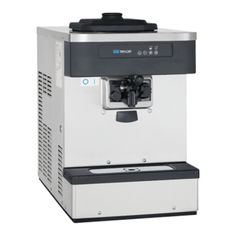
- Page 1 OPERATOR’S MANUAL Model C152 and C161 Soft Serve Freezer Original Service Instructions 1/23/2017 (Original Publication) 085592-M (Updated 7/29/20)
- Page 2 Note: Only instructions originating from the factory or its authorized translation representative(s) are considered to be the original set of instructions. © 2017 Taylor Company 085592-M Any unauthorized reproduction, disclosure, or distribution of copies by any person of any portion of this work may be...
-
Page 3: Table Of Contents
Operator Information ..................2-1 Section 3: Safety Section 4: Operator Parts Identification Model C152......................4-1 Model C161......................4-2 C152 Beater Door Assembly................4-3 C161 Beater Door Assembly................4-4 C152 Accessories ....................4-5 C161 Accessories ....................4-6 Section 5: User Interface C152........................ - Page 4 Sanitizing......................6-5 Priming .......................6-6 Closing Procedure....................6-7 Draining Product from the Freezing Cylinder .............6-7 Rinsing .......................6-7 Cleaning ......................6-7 Disassembly .......................6-7 Brush Cleaning....................6-8 Section 7: Operator Checklist During Cleaning and Sanitizing ................7-1 Troubleshooting Bacterial Count ................7-1 Regular Maintenance Checks ................7-1 Winter Storage ....................7-2 Section 8: Troubleshooting Guide Section 9: Parts Replacement Schedule Maintenance Intervals ..................9-1...
-
Page 5: Section 1: To The Installer
Do not obstruct air intake and discharge openings. electrical shock or hazardous moving parts as well as Model C152 requires 4 in. (102 mm) of space on both poor performance or damage to the machine. sides, and no space at the rear. Model C161 requires ... -
Page 6: Water Connections
TO THE INSTALLER Water Connections Water-Cooled Machines Only: An adequate cold water supply must be provided with a hand shutoff valve. On IMPORTANT! An equipotential grounding lug is the underside rear of the base pan, two 3/8 in. I.P.S. provided with this machine. Some countries require the water connections for inlet and outlet have been provided grounding lug be properly attached to the rear of the for easy hookup. -
Page 7: Refrigerant
For information regarding applicable local laws, This machine's type of gas, quantity, Global Warming please contact your local authorized Taylor distributor. Potential (GWP), and CO tonnes equivalent information is recorded on the machine's data-label. The refrigerant used is generally considered non-toxic and non- flammable. - Page 8 TO THE INSTALLER Notes: 085592-M To the Installer...
-
Page 9: Section 2: To The Operator
To the Operator Section 2 Operator Information Note: Your Taylor warranty is valid only if the parts are authorized Taylor parts purchased from the local This soft serve freezer has been carefully engineered authorized Taylor distributor, and only if all required and manufactured to give you dependable operation. - Page 10 It should also be noted that Taylor does not warrant the refrigerant used in its equipment. For example, if the refrigerant is lost during the course of ordinary service to...
-
Page 11: Section 3: Safety
Safety Section 3 We at Taylor Company are concerned about the safety of used. NEVER use a water jet or hose to rinse or clean operators at all times when they are coming in contact the machine. Failure to follow this instruction may result with the machine and its parts. - Page 12 4 in. (102 mm) on both sides, and 0 in the personal injury, especially to fingers or hands, from rear is required for Model C152. A minimum of 6 in. (152 hazardous moving parts. mm) on both sides, and 0 in the rear is required for Model C161.
-
Page 13: Model C152
Operator Parts Identification Section 4 Model C152 14 15 Figure 4-1 Item Description Part No. Item Description Part No. Pan-Drip 085295 Shield-Splash 086379 Panel-Left 086378 Panel-Lower Front 086380 Cover A.-Hopper X49633-SP Panel-Front 086384 Tube-Feed 035819 Trim-Corner-Rear 086375 Panel-Rear 086376 Plate-Dec... -
Page 14: Model C161
OPERATOR PARTS IDENTIFICATION Model C161 Figure 4-2 Item Description Part No. Item Description Part No. Pan-Drip 085295 Tray-Drip 16-7/8L X 4-5/16 085699 Panel-Side-Left 085262 Shield-Splash 085304 Cover A.-Hopper 085351 Panel-Lower Front X85729-SER Tube-Feed 030797 Panel A.-Front 085678 Panel-Rear 085274 Plate-Dec X85775 Panel A.-Side-Right X69433... -
Page 15: C152 Beater Door Assembly
OPERATOR PARTS IDENTIFICATION C152 Beater Door Assembly Figure 4-3 Item Description Part No. Item Description Part No Valve-Draw 024763-SP1 Cap-Design 1.010"ID-6 PT. 014218 O-Ring-7/8 OD X.103W 014402 Bearing-Guide 014496 Door A.-3SPT 1.5QT VALOX X86373-SER O-Ring-2-3/4 OD X .139W 019998 Pin A.-Pivot-Short... -
Page 16: C161 Beater Door Assembly
OPERATOR PARTS IDENTIFICATION C161 Beater Door Assembly Figure 4-4 Item Description Part No. Item Description Part No Valve-Draw 024763-SP1 Cap-Design 1.010"ID-6 PT. 014218 O-Ring-7/8 OD X.103W 014402 Pin A.-Pivot-Long X38538 Seal-Draw Valve *Small H-Ring* 030930 Valve-Draw-Center 031164-SP Door A.-3SPT 1.5QT VALOX X56906SER3 Bearing-Guide 014496... -
Page 17: C152 Accessories
OPERATOR PARTS IDENTIFICATION C152 Accessories Apply the appropriate Taylor approved food safe lubricant. Figure 4-5 Item Description Part No Item Description Part No. Pail-6 qt. 023348 Lubricant-Taylor 4 oz. 047518 Brush-Rear BRG 1” D X 2” LG 013071 Kit·A.-Tune Up X25802 Brush-Double·Ended... -
Page 18: C161 Accessories
OPERATOR PARTS IDENTIFICATION C161 Accessories Apply the appropriate Taylor approved food safe lubricant. Figure 4-6 Item Description Part No Item Description Part No. Pail-6·QT. 023348 Lubricant-TAYLOR·4·OZ. 047518 Brush-Rear BRG 1” D X 2” LG 013071 Kit·A.-Tune·Up X31167 Brush-Double·Ended 013072 Leg (Optional) 036397 Brush-Draw·Valve·1”... -
Page 19: C152
User Interface Section 5 C152 RESET C161 RESET Item Description Item Description Power Switch AUTO Key MIX REF Key Indicator Light Mix Low STANDBY Key Reset Button WASH Key Indicator Light Mix Out User Interface 085592-M... -
Page 20: Symbol Definitions
Your Taylor This will prevent mix from entering the freezing equipment is designed with these international symbols. -
Page 21: Wash Key
Reset Button The reset button is located on the side of the C152 unit and on the front of the C161 unit. The reset protects the beater motor from an overload condition. If an overload occurs, the reset mechanism will trip. -
Page 22: Feed Tube
USER INTERFACE Feed Tube • Standby Operation: During long “no sale” periods, the air orifice is removed and the feed tube is The feed tube maintains overrun and allows enough mix inverted. The end of the feed tube without the mix to enter the freezing cylinder after a draw. -
Page 23: Section 6: Operating Procedures
Model C152 is a counter model with a single spout door. 11456 Model C161 is a counter model with three spout doors. - Page 24 Do not overtighten the handscrews. 10335 Apply the appropriate Taylor approved food safe lubricant. Figure 6-4 Figure 6-6 5. Slide the front bearings over the baffle rods so that the flanged edge is against the door. Place the white Important! Handscrew and door damage can result if the plastic guide bearings on the end of the baffle rods.
- Page 25 12. Slide the O-ring onto each pivot pin and lubricate. remaining draw valves and lubricate. 10131a 11070 Apply the appropriate Taylor approved food safe lubricant. Apply the appropriate Taylor approved food safe lubricant. Figure 6-10 Figure 6-8 13. Slide the tip of the draw handle into the slot of the 11.
- Page 26 OPERATING PROCEDURES 14. Snap the design caps over the bottom of the freezer 16. Install the air orifice to the end of the feed tube door spouts. without the hole in the side. Figure 6-12 Figure 6-14 15. Install the O-ring onto the groove of the air orifice. Do 17.
-
Page 27: Sanitizing
OPERATING PROCEDURES 20. Install the drip pan. 3. While the solution is flowing into the freezing cylinder, brush clean the mix hopper, the mix inlet hole, and the feed tube. 12235 Figure 6-16 Sanitizing Figure 6-18 12019 1. Prepare an approved 100 PPM sanitizing solution ®... -
Page 28: Priming
OPERATING PROCEDURES Priming 5. Press the WASH key to cause the sanitizing solution in the freezing cylinder to be agitated. Allow it to Prime the machine as close as possible to the time of first agitate for five minutes. product draw. 13054w 1. -
Page 29: Closing Procedure
OPERATING PROCEDURES Rinsing 4. (For Model C161) Repeat step 1 through step 3 for the other side of the machine. 1. Pour 1 gal. (3.8 L) of cool, clean water into the mix 5. Place the mix hopper cover in position. hopper. -
Page 30: Brush Cleaning
OPERATING PROCEDURES Brush Cleaning 1. Prepare a sink with an approved cleaning solution ® ® or Stera-Sheen (examples: Kay-5 ). Use warm water and follow the manufacturer's specifications. Important! Follow label directions. Too strong of a solution can cause parts damage, while too weak of a solution will not provide adequate cleaning. -
Page 31: Section 7: Operator Checklist
Operator Checklist Section 7 During Cleaning and Sanitizing break the rerun cycle and reduce the possibility of high bacteria and coliform counts. Properly prepare the cleaning and sanitizing ALWAYS FOLLOW LOCAL HEALTH CODES. solutions. Read and follow label directions carefully. -
Page 32: Winter Storage
Wrap detachable parts of the freezer, such as the maintenance purposes. Deteriorated or cracked beater assembly and freezer door, and place them in water lines should be replaced only by a Taylor a protected dry place. Rubber trim parts and gaskets service technician. -
Page 33: Section 8: Troubleshooting Guide
The rear shell bearing is worn. b. Contact service technician. c. Incorrect lubricant was used. c. Use food grade lubricant (example: Taylor Lube). d. Inadequate lubrication of beater d. Lubricate the beater drive shaft drive shaft. properly. - Page 34 7. The draw valve is a. Incorrect lubricant was used. a. Use food grade lubricant (example: leaking. Taylor Lube). b. Worn or defective O-rings are on b. Replace O-rings every 3 months. the draw valve. c. Inadequate lubrication of draw c.
-
Page 35: Maintenance Intervals
Section 9 Maintenance Intervals Table 9-1 Part Description Every 3 Months Every 6 Months Annually C152 Qty. C161 Qty. Beater Drive Shaft Cup Seal Freezer Door O-Ring Freezer Door Front Bearing Freezer Door Guide Bearing Draw Valve O-Ring Center Draw Valve Seal Pivot Pin O-Ring Black Bristle Brush, 1”... - Page 36 PARTS REPLACEMENT SCHEDULE Notes: 085592-M Parts Replacement Schedule...
-
Page 37: Section 10: Limited Warranty On Equipment
Taylor, through a Taylor-authorized Taylor distributor or service agency, will provide a new or re-manufactured part, at Taylor's option, to replace the failed defective part at no charge for the part. Except as otherwise stated herein, these are Taylor's exclusive obligations under this limited warranty for a Product failure. This limited warranty is subject to all provisions, conditions, limitations, and exclusions listed below and on the reverse (if any) of this document. - Page 38 7. Failure, damage, or repairs due to faulty installation, misapplication, abuse, no or improper servicing, unauthorized alteration, or improper operation or use as indicated in the Taylor Operator's Manual, including but not limited to the failure to use proper assembly and cleaning techniques, tools, or approved cleaning supplies.
- Page 39 LEGAL REMEDIES The owner must notify Taylor in writing by certified or registered letter to the following address of any defect or complaint with the Product, stating the defect or complaint and a specific request for repair, replacement, or other correction of the Product under warranty, mailed at least thirty (30) days before pursuing any legal rights or remedies.
- Page 40 LIMITED WARRANTY ON EQUIPMENT Notes: 10-4 085592-M Limited Warranty on...
-
Page 41: Section 11: Limited Warranty On Parts
Taylor warrants the Parts against failure due to defect in materials or workmanship under normal use and service as follows. All warranty periods begin on the date of original installation of the Part in the Taylor unit. If a Part fails due to defects during the applicable warranty period, Taylor, through a Taylor-authorized distributor or service agency, will provide a new or remanufactured Part, at Taylor's option, to replace the failed defective Part at no charge for the Part. - Page 42 Taylor. 5. Replacement of wear items designated as Class 000 Parts in the Taylor Operator's Manual, as well as any release sheets and clips for the Product's upper platen assembly.
- Page 43 LEGAL REMEDIES The owner must notify Taylor in writing by certified or registered letter to the following address of any defect or complaint with the Part, stating the defect or complaint and a specific request for repair, replacement, or other correction of the Part under warranty, mailed at least thirty (30) days before pursuing any legal rights or remedies.
- Page 44 LIMITED WARRANTY ON PARTS Notes: 11-4 085592-M Limited Warranty on Parts...
Need help?
Do you have a question about the C152 and is the answer not in the manual?
Questions and answers