
Related Manuals for DeLonghi DSC 606G


Summary of Contents for DeLonghi DSC 606G
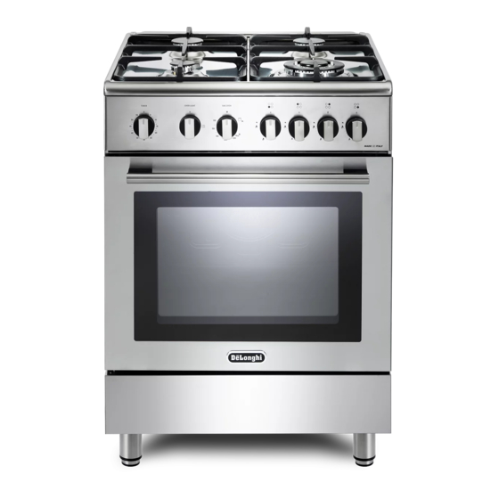
- Page 1 DE ’ L O N G H I C OO KING USER & INSTALLATION INSTRUCTIONS D SC 606 G G AS C O O KE R...
-
Page 2: Table Of Contents
CONTENTS Page Number Introduction....................3 Important Safeguards & Recommendations........... 4-8 Advice for the installer................. 9 Installation....................10-14 Gas installation..................15-24 Electrical section..................25-26 Advice for the user................. 27 Cooking Hob.................... 28 Control Panel..................29 Use of the hob burners................30-32 Gas oven.................... -
Page 3: Introduction
Dear Customer, Thank you for purchasing the DeLonghi DSC 606G Gas Cooker. The safety precautions and recommendations listed below are for your own safety and that of others. They will also provide a means by which to make full use of the features offered by your appliance. -
Page 4: Important Safeguards & Recommendations
IMPORTANT SAFETY PRECAUTIONS AND RECOMMENDATIONS IMPORTANT: This appliance is designed and manufactured solely for the cooking of domestic (household) food and is not suitable for any non domestic application and therefore should not be used in a commercial environment. The appliance guarantee will be void if the appliance is used within a non domestic environment i.e. - Page 5 • Do not attempt to modify the technical characteristics of the appliance as this may become dangerous to use. The manufacturer declines all responsibility for any inconvenience resulting from the inobservance of this condition. • CAUTION: this appIiance must only be installed in a permanently ventilated room in compliance with the applicable regulations.
- Page 6 • The manufacturer declines all liability for injury to persons or damage to property caused by incorrect or improper use of the appliance. • WARNING: During use the appliance and its accessible parts become hot; they remain hot for some time after use. Care should be taken to avoid touching heating elements (on –...
- Page 7 • CAUTION: Do not use harsh abrasive cleaners or sharp metal scrapers to clean the oven door glass since they can scratch the surface, which may result in shattering of the glass. • Do not line the oven walls or base with aluminium foil. Do not place baking trays or the drip tray on the base of the oven chamber.
- Page 8 ENERGY LABELLING/ECODESIGN • Commission delegated regulation (EU) No 65/2014 (supplementing Directive 2010/30/EU of the European Parliament and of the Council). • Commission regulation (EU) No 66/2014 (implementing Directive 2009/125/EC of the European Parliament and of the Council). Reference to the measurement and calculation methods used to establish compliance with the above requirements: •...
-
Page 9: Advice For The Installer
Advice for the installer... -
Page 10: Installation
1 - INSTALLATION IMPORTANT • The appliance is designed and approved for domestic use only and should not be installed in a commercial, semi commercial or communal environment. Your product will not be guaranteed if installed in any of the above environments and could affect any third party or public liability insurances you may have. - Page 11 This cooker has class “2/1” overheating protection so that it can be installed next to a cabinet. If the cooker is installed adjacent to furniture which is higher than the gas hob cooktop, a gap of at least 200 mm must be left between the side of the cooker and the furniture. The walls and kitchen furniture surrounding the appliance must be made of non-flammable material.
- Page 12 FITTING THE ADJUSTABLE FEET The adjustable feet must be fitted to the base of the cooker before use (fig. 1.2a). Rest the rear of the cooker on a piece of the polystyrene packaging exposing the base for the fitting of the feet. Fit the 4 legs by screwing them tight into the support base as shown in figure 1.2a.
- Page 13 MOVING THE COOKER WARNING: When raising cooker to upright position always ensure two people carry out this manoeuvre to prevent damage to the adjustable feet (fig. 1.4). Fig. 1.4 WARNING Be carefull: do not lift the cooker by the door handle when raising to the upright position (fig.
- Page 14 PROVISION FOR VENTILATION • The appliance should be installed into a room or space with an air supply in accordance with the current version of BS 5440-2: 2000. • For rooms with a volume of less than 5m - permanent ventilation of 100 cm free area must be provided.
-
Page 15: Gas Installation
2 - GAS INSTALLATION IMPORTANT NOTE This appliance is supplied for use on NATURAL GAS or LPG (check the gas regulation label attached on the appliance). • Appliances supplied for use on NATURAL GAS are adjusted for this gas only and cannot be used on any other gas (LPG) without modification. - Page 16 RESTRAINING CHAIN Fig. 2.1 Chain security holes Cooker Back of the cooker Rear wall Installation to Natural Gas Installation to Natural Gas must conform to the Code of Practice, etc. The supply pressure for Natural Gas is 20 mbar. The installation must conform to the relevant British/European Standards. Installation to LP Gas When operating on Butane gas a supply pressure of 28-30 mbar is required.
- Page 17 Notes: Flexible hoses can be used where the sited ambient temperature of the hose • does not exceed 70°C. These hoses must be manufactured in accordance with BS669 part 1 or EN 14800 and be of the correct construction for the type of gas being used.
- Page 18 Fitting the plug Fig. 2.3 on the inlet pipe terminal not used Cooker manifold (right Cooker or left inlet pipe) manifold (right or left inlet pipe) Manifold male Manifold pipe fitting male 1/2” G cylindrical pipe fitting (ISO 228-1) male 1/2”...
- Page 19 Conversion to Natural Gas or to LPG REPLACEMENT Auxiliary and INJECTORS OF THE TOP BURNERS semi-rapid burners If the injectors are not supplied they can be obtained from the After-Sales Service. Select the injectors to be replaced according to the “Table for the choice of the injectors”.
- Page 20 TABLE FOR THE CHOICE OF THE INJECTORS Cat: 2H3+ Natural gas G30 (28-30 mbar) Nominal Reduced G20 20 mbar G31 (37 mbar) BURNERS power power Ring Ring [kW] [kW] Ø injector Ø injector opening opening [1/100 mm] [1/100 mm] [mm] [mm] Auxiliary (A) 1,00...
- Page 21 OPERATIONS TO BE EXECUTED FOR THE REPLACEMENT OF THE INJECTORS OF THE OVEN AND GRILL BURNERS Some models are provided with a set of injectors for the various types of gas. If the injectors are not supplied they can be obtained from the “Service Centre”. Select the injectors to be replaced according to the “Table for the choice of the injectors”...
- Page 22 GRILL BURNER • Unscrew and remove the burner securing screw “A” (fig. 2.10). • Withdraw the burner as shown in figure 8.8b. Take care not to damage the safety valve probe and the electric ignition electrode. • Using a 7 mm box spanner, unscrew the injector (indicated by the arrow in fig. 2.11) and replace it with a new one selected in accordance with the “Table for the choice of the injectors”.
- Page 23 REGULATION OF AIR SUPPLY TO OVEN AND GRILL BURNERS To regulate the air supply it is necessary to remove the burners from their housings (figs. 2.10 - 2.11). • Using a cross-head screwdriver, slacken the screws “A” securing the air flow regulation collar “B”...
- Page 24 Flame Flame Flame correct Flame faulty in with excess correct primary air primary air short and flong, yellow clear sharp too Flame faulty in interior blue blue interior primary air trembling cone cone tending to detach CAUSE Flame with excess air regulating correct air regulating...
-
Page 25: Electrical Section
3 - ELECTRICAL INSTALLATION IMPORTANT: The cooker must be installed in accordance with the manufacturer’s instructions. Incorrect installation, for which the manufacturer accepts no responsibility, may cause damage to persons, animals and things. The connection of the appliance to earth is mandatory. The manufacturer declines all responsability for any inconvenience resulting from the inobservance of this condition. - Page 26 CONNECTION OF THE POWER SUPPLY CABLE WARNING: If the power supply cable is damaged, it must be replaced only by an authorised service agent in order to avoid a hazard. • Unhook the terminal board cover by inserting a screwdriver into the two hooks “A” (fig. 3.2).
-
Page 27: Advice For The User
Advice for the user... -
Page 28: Cooking Hob
1 - COOKING HOB Fig. 1.1 GAS BURNERS 1. Auxiliary burner (A) 1,00 kW 2. Semi-rapid burner (SR) 1,75 kW 3. Triple-ring burner (TR) 3,50 kW Notes: • The electric ignition is incorporated in the knobs. • The appliance has a safety valve system fitted, the flow of gas will be stopped if and when the flame should accidentally go out. -
Page 29: Control Panel
2 - CONTROL PANEL Fig. 2.1 OVEN LIGHT GAS OVEN CONTROLS DESCRIPTION Front right burner control knob Rear right burner control knob Rear left burner control knob Front left burner control knob Gas oven/gas grill thermostat control knob Oven light control knob 60’... -
Page 30: Use Of The Hob Burners
3 - USE OF THE HOB BURNERS GAS BURNERS Gas flow to the burners is adjusted by turning the knobs (illustrated in fig. 3.1) which control the safety valves. Turning the knob, so that the indicator line points to the symbols printed on the panel, achieves the following functions: - symbol closed valve... - Page 31 LIGHTING THE BURNERS CHOICE OF THE BURNER ignite burner, following On the control panel, near every knob instructions are to be followed: there is a diagram that indicates which Press in the corresponding knob and burner is controlled by that knob. turn counter-clockwise (fig.
- Page 32 CORRECT USE OF THE TRIPLE-RING Only flat bottom pans of the correct size are to be placed on the pan support above the Triple-ring burner. When using a WOK, the supplied wok stand must be placed onto the pan stand to avoid any faulty operation of the triple-ring burner (fig.
-
Page 33: Gas Oven
4 - GAS OVEN COOLING FAN MOTOR ATTENTION: This appliance incorporates a safety The oven door becomes very hot cooling fan motor to achieve optimum during operation and very hot steam efficiency of the controls, ensure lower goes out from the area below the surface temperatures are maintained and control panel. - Page 34 OVEN BURNER THERMOSTAT The numbers 130 to Max printed on The gas flow to the burner is regulated by the control panel (fig. 4.2) indicate the a thermostat which allow to maintain the increasing oven temperature value. oven temperature constant. The temperature is kept constant on the The control of the temperature is assured by a thermostatic probe positioned inside...
- Page 35 LIGHTING OF OVEN BURNER During and after use of the oven, IMPORTANT: The oven door must be certain parts will become very hot. open during this operation. Keep children away. To light the oven burner: ATTENTION: case manual 1 – Open the oven door to the full lighting, never turn the thermostat extent.
- Page 36 LIGHTING OF GAS GRILL BURNER ATTENTION: The oven door becomes very during operation. Keep IMPORTANT: The oven door must be children away. open during this operation. To light the grill burner: During and after use of the grill, certain 1 – Open the oven door to the full parts will become very hot.
- Page 37 OVEN LIGHT COOKING WITH GAS OVEN The oven provides an interior lamp to allow Once the oven gas burner has been lit, the visual inspection during the cooking. close the oven door and preheat the oven To light the oven lamp turn the knob (fig. for at least 15 minutes.
-
Page 38: Minute Timer
5 - 60 MINUTE TIMER MINUTE COUNTER The minute counter is a timed acoustic warning device which can be set for a maximum of 60 minutes. The knob (fig. 5.1) must be rotated clockwise as far as the 60 minute position and then set to the required time by rotating it anticlockwise. -
Page 39: Cleaning & Maintenance
6 - CLEANING AND MAINTENANCE GENERAL ADVICE WARNING: When correctly installed, your product • Before you begin cleaning, you meets all safety requirements laid down must ensure that the appliance is for this type of product category. switched off at the cooker switch. However special care should be taken •... - Page 40 CORRECT REPLACEMENT OF THE • Burner bodies (aluminium alloy): TRIPLE RING BURNER They should be cleaned with soapy water and a clean cloth. For stubborn The triple ring burner must be correctly stains a proprietary cream or stainless positioned (see fig. 6.5); the burner rib steel cleaner may be used;...
- Page 41 Fig. 6.1 Fig. 6.2 Fig. 6.3 Fig. 6.4 Fig. 6.5...
- Page 42 ASSEMBLY AND DISMANTLING OF THE SIDE RUNNER FRAMES • Fit the side runner frames into the holes on the side walls inside the oven (fig. 6.6). • Slide the rack into the runners (fig. 6.7). The rack must be fitted so that the safety notch, which stops it sliding out, faces the inside of the oven;...
- Page 43 REMOVING THE OVEN DOOR The oven door can easily be removed as follows: • Open the door to the full extent (fig. 6.11). • Open the lever “A” completely on the left and right hinges (fig. 6.12). • Hold the door as shown in fig. 6.10. Fig.
- Page 44 REFIT THE DOOR • Hold the door firmly (fig. 6.15). • Insert the hinge tongues into the slots, making sure that the groove drops into place as shown in the fig. 6.16. • Open the door to its full extent. •...
- Page 45 REMOVING THE INNER PANE OF GLASS The oven door is fitted with no. 2 panes: • no. 1 outside; • no. 1 inner. To clean all panes on both sides it is necessary to remove the inner pane as follows: Lock the door open: Fig.
- Page 46 AFTER CLEANING, REPLACE THE INNER GLASS PANE When replacing the inner glass pane, make sure that: • You replace the pane correctly, as shown. The pane must be in the position described below in order to fit into the door and to ensure that the oven operates safely and correctly.
-
Page 47: Guarantee & After Sales Service
7 - GUARANTEE Your new “De’Longhi” product comes with 12-month guarantee covering all parts and labour. If your appliance proves to be defective as a result of faulty materials or workmanship during the guarantee period, these parts will be repaired or replaced free of charge. AFTER SALES SERVICE Should you require service, spares or product information and advice: •... - Page 48 De scri pt io n s a n d il lu st ra tio ns in th is b o ok let ar e g iv en a s simply indicati ve. Th e m an u fa ctu rer re se rv es th e r igh t,...
Need help?
Do you have a question about the DSC 606G and is the answer not in the manual?
Questions and answers