Sign In
Upload
Manuals
Brands
Elektro-Automatik Manuals
Power Supply
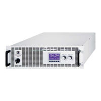
PSI 8040-170 3U
Elektro-Automatik PSI 8040-170 3U Manuals
Manuals and User Guides for Elektro-Automatik PSI 8040-170 3U. We have
2
Elektro-Automatik PSI 8040-170 3U manuals available for free PDF download: Operating Manual, Instruction Manual
Elektro-Automatik PSI 8040-170 3U Operating Manual (80 pages)
DC High Efficiency Power Supply
Brand:
Elektro-Automatik
| Category:
Power Supply
| Size: 5 MB
Table of Contents
Deutsch
4
Table of Contents
4
Technische Daten
6
Bedien- und Anzeigeeinheit
6
Einleitung
6
Gerätespezifische Daten
7
Gerätebeschreibung
11
Ansichten
11
Installation
14
Netzanschluß (Mehrere Geräte)
14
Netzanschluß (Einzelgerät)
14
Sichtprüfung
14
Kühlung
14
Redundanz
14
Gerät Öffnen
14
Vorwort
14
Allgemeines zum Gerät
14
Lieferumfang
14
Netzsicherungen
15
Anschluß DC-Ausgang
15
Anschlußtypen
15
Slot für Erweiterungskarte
16
Anschlußklemme Fernfühlung (Sense)
16
Anschlußklemme Share
16
Erdung des Ausganges
16
Bedienung
17
Die Anzeige
17
Verwendete Symbolik
17
Übersicht über die Anzeigeelemente
17
Gerät Einschalten
18
Einschalten des Ausgangs
18
Sollwerte Einstellen
18
Bedienorte
19
Bedieneinheit Sperren
19
Tastenfeld Umschalten
19
Umschalten in den Funktionsmanager
20
Umschalten ins Menü
20
Parameterseiten
20
Alarme, Warnungen und Meldungen
20
Quittieren von Alarmen und Warnungen
21
Der Funktionsmanager
21
Festlegung der Sequenzpunkte
22
Sequenzbezogene Parameter
22
Sequenzen Festlegen
22
Der Funktionsaufbau
22
Funktionsablauf Konfigurieren
22
Anzeige während des Funktionsablaufs
23
Steuern des Funktionsmanagers
23
Gerätekonfiguration
24
Betriebsparameter Definieren
25
Voreinstellung von Sollwertsätzen
25
Einstellgrenzen
25
Bedieneinheit Konfigurieren
26
Spannungsüberwachung
27
Überwachung
27
2006, Elektro-Automatik Gmbh & Co. KG Irrtümer und Änderungen Vorbehalten
27
Display Einstellen
27
Stromüberwachung
28
Sollwertsprünge Überwachen
29
Grundeinstellung Wiederherstellen
30
Freischaltung der U/I/R Betriebsart
30
Sperren der Geräte-Konfiguration
30
Spannungs-, Strom- und Leistungsregelung
31
Übertemperaturalarm
31
Überspannungsalarm
31
Umschalten auf Fernsteuerung (Remote)
31
Ausschalten mit dem Netzschalter
31
Besondere Gegebenheiten
31
Einschalten mit dem Netzschalter
31
Fernfühlungsbetrieb
32
Netzüber-/Netzunterspannung
32
Anschluß Verschiedener Lasttypen
32
Interne Analogschnittstelle
33
Übersicht Sub-D-Buchse
33
Schnittstellenkarten Konfigurieren
33
Allgemeines
33
Digitale Schnittstellen
33
Einstellungen zur Int. Analogschnittstelle
34
Beispielanwendungen
34
Spezifikation der Anschlüsse
36
Weitere Anwendungen
36
Parallelschaltung IM Sharebus-Betrieb
36
Reihenschaltung
38
Verschiedenes
38
Zubehör und Optionen
38
Vernetzung
38
Option: Innenwiderstandsregelung
39
Firmwareaktualisierung
39
Ersatzableitstrommessung nach DIN VDE 0701
39
English
42
2006, Elektro-Automatik Gmbh & Co. KG Irrtümer und Änderungen Vorbehalten
44
Control Panel and Display
44
Introduction
44
Technical Specifications
44
Device Specifications
45
Device Description
49
Views
49
Cooling
52
General
52
Input Connection (Multiple Units)
52
Input Connection (Single Unit)
52
Installation
52
Opening the Device
52
Prologue / Warning
52
Redundancy
52
Scope of Delivery
52
Visual Check
52
DC Output Terminal
53
Input Fuses
53
Terminal Types
53
Grounding the Output
54
Interface Card Slot
54
Terminal „Sense" (Remote Sense)
54
Terminal „Share
54
Handling
55
Short Overview about the Display Elements
55
The Display
55
Used Symbols
55
Adjusting Set Values
56
Switching the Power Output on
56
Switching the Unit on
56
Control Locations
57
Locking the Control Panel
57
Switching the Button Panel
57
Activating the Menu
58
Alarms, Warnings and Signals
58
Parameter
58
Switching to the Function Manager
58
Acknowledging Alarms and Warnings
59
The Function Manager
59
Configuring Sequences
60
Configuring the Function
60
Defining the Sequence Points
60
Sequence Related Parameters
60
The Function Layout
60
Controlling the Function Manager
61
Display During the Function Run
61
Device Configuration
62
Adjustment Limits
63
Defining Operation Parameters
63
Predefining Preset Lists
63
Configuring the Control Panel
64
Configuring the Graphic Display
65
Supervision
65
Voltage Supervision
65
Current Supervision
66
Step Response Supervision
67
Locking the Device Configuration
68
Reset to Default Configuration
68
Unlocking the U/I/R Mode
68
Overtemperature Alarm
69
Overvoltage Alarm
69
Special Characteristics
69
Switching off by Power Switch
69
Switching on by Power Switch
69
Switching to Remote Control
69
Voltage, Current and Power Regulation
69
Connecting Different Types of Loads
70
Mains Undervoltage or Overvoltage
70
Remote Sense
70
Configuring the Interface Card
71
Digital Interfaces
71
General
71
Internal Analog Interface
71
Overview D-Sub Socket
71
Example Applications
72
Settings for the Internal Analog Interface
72
Other Applications
74
Parallel Connection with Share Bus
74
Pin Specifications
74
Accessories and Options
76
Miscellaneous
76
Networking
76
Series Connection
76
Firmware Update
77
Option: Internal Resistance
77
Advertisement
Elektro-Automatik PSI 8040-170 3U Instruction Manual (74 pages)
Brand:
Elektro-Automatik
| Category:
Power Supply
| Size: 8 MB
Table of Contents
Table of Contents
4
技术规格
6
控制面板和显示器
6
各型号详细规格
7
产品描述
11
各面视图
11
供应清单
14
一般信息
14
序言/安全警告
14
打开产品
14
冗余操作
14
输入端连接(单机
14
输入端连接(多台机
14
输入保险丝
15
直流输出端
15
输出端类型
15
输出端接地
16
Sense"(远程感测)端
16
Share"(共享)端
16
接口卡插槽
16
使用符号
17
各显示元素简介
17
打开功率输出
18
调节设定值
18
设定值调节步宽
18
2006, Elektro-Automatik Gmbh & Co. KG Irrtümer Und Änderungen Vorbehalten
18
转换按钮面板
19
锁定控制面板
19
更改定位模式
19
转至函数管理器
19
激活菜单
19
参数页
19
报警、警告和信号提示
19
报警和警告的确认
19
函数管理器
20
配置函数
20
函数布局
20
配置序列
21
与序列有关的参数
21
函数运行时的显示
21
函数运行时的显示
22
函数管理器的控制
22
产品设置
23
定义操作参数
24
预定义预设清单
24
调节极限
25
配置控制面板
25
配置图显
26
2006, Elektro-Automatik Gmbh & Co. KG Irrtümer Und Änderungen Vorbehalten
26
电压监控
26
电流监控
27
阶跃响应监控
28
恢复至默认配置
29
解锁U/I/R运行模式
29
锁定产品配置
29
下列情形发生时的反应
30
用电源开关打开
30
用电源开关关闭
30
转至远程控制模式
30
出现过压
30
出现过温
30
调整电压、电流和功率
30
远程感测被激活
30
市电出现欠压或过压
30
连接不同类型的负载
31
数字接口卡
31
一般信息
31
配置接口卡
31
模拟接口
32
一般信息
32
引脚图
32
产品设置下的设定
33
应用举例
33
模拟接口各引脚分布
34
其它应用
35
共享总线模式下的并联
35
其它附件和选项功能
35
固件更新
37
Introduction
42
Technical Specifications
42
Control Panel and Display
42
Device Specifications
43
Device Description
47
Views
47
Scope of Delivery
50
General
50
Prologue / Warning
50
Cooling
50
Opening the Device
50
Redundancy
50
Installation
50
Visual Check
50
Input Connection (Single Unit)
50
Input Connection (Multiple Units)
50
Input Fuses
51
DC Output Terminal
51
Terminal Types
51
Grounding the Output
52
Terminal „Sense" (Remote Sense)
52
Terminal „Share
52
Interface Card Slot
52
Handling
53
The Display
53
Used Symbols
53
Short Overview about the Display Elements
53
Switching the Power Output on
54
Adjusting Set Values
54
Step Widths for Set Value Adjustment
55
Switching the Button Panel
55
Locking the Control Panel
55
Changing the Location Mode
55
Switching to the Function Manager
55
Activating the Menu
55
Parameter
56
Alarms, Warnings and Signals
56
Acknowledging Alarms and Warnings
56
The Function Manager
57
Configuring the Function
57
The Function Layout
58
Configuring Sequences
58
Sequence Related Parameters
58
Defining the Sequence Points
58
Display During the Function Run
58
Controlling the Function Manager
59
Device Configuration
60
Defining Operation Parameters
61
Predefining Preset Lists
61
Adjustment Limits
62
Configuring the Control Panel
62
Configuring the Graphic Display
63
Supervision
63
Voltage Supervision
63
Current Supervision
64
Step Response Supervision
65
Reset to Default Configuration
66
Unlocking the U/I/R Mode
66
Locking the Device Configuration
66
Behaviour of the Device When
67
Switching on by Power Switch
67
Switching off by Power Switch
67
Switching to Remote Control
67
Overvoltage Occurs
67
Overtemperature Occurs
67
Voltage, Current and Power Are Regulated
67
Remote Sense Is Active
68
Mains Undervoltage or Overvoltage Occurs
68
Connecting Different Types of Loads
68
Digital Interfaces
69
General
69
Configuring the Interface Cards
69
Analogue Interface
69
Pin Overview
69
Settings in the Device Setup
70
Pin Specifications
71
Example Applications
71
Miscellaneous
72
Parallel Connection in Share Bus Mode
72
Series Connection
72
Accessories and Options
74
Firmware Update
74
Networking
74
Advertisement
Related Products
Elektro-Automatik PSI 8040-340 3U
Elektro-Automatik PSI 8040-510 3U
Elektro-Automatik PSI 8040-60 2U
Elektro-Automatik PSI 8040-120 2U
Elektro-Automatik PSI 8000 3U HS PV Series
Elektro-Automatik PSI 8000 T
Elektro-Automatik PSI 8032-10T
Elektro-Automatik PSI 8065-05T
Elektro-Automatik PSI 8065-10T
Elektro-Automatik PSI 8080-40 2U
Elektro-Automatik Categories
Power Supply
UPS
Enclosure
Test Equipment
Laboratory Equipment
More Elektro-Automatik Manuals
Login
Sign In
OR
Sign in with Facebook
Sign in with Google
Upload manual
Upload from disk
Upload from URL