
Related Manuals for Teknik Spanish Style Desk 5420114


Summary of Contents for Teknik Spanish Style Desk 5420114
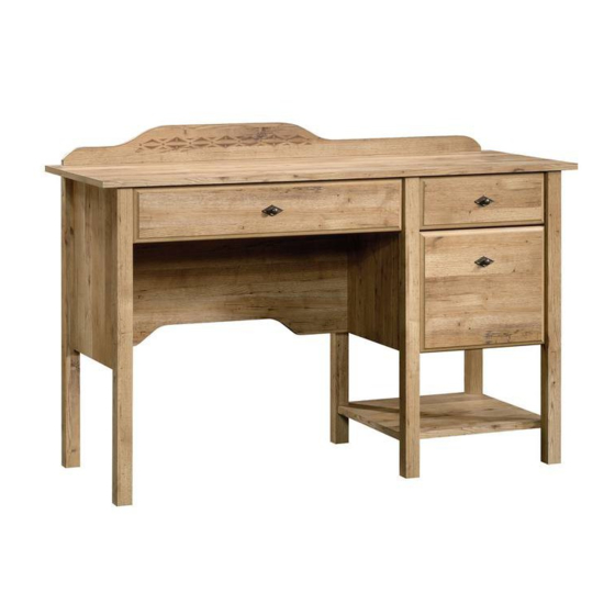
- Page 1 Teknik www.teknikoffice.co.uk The original desktop. Spanish Style Desk Model 5420114 NOTE: THIS INSTRUCTION BOOKLET CONTAINS IMPORTANT SAFETY INFORMATION. PLEASE READ AND KEEP FOR FUTURE REFERENCE.
- Page 2 Table of Contents Assembly Tools Required Part Identifi cation No. 2 Phillips Screwdriver Tip Shown Actual Size Hardware Identifi cation Assembly Steps 6-32 Hammer Not actual size Skip the power trip. This time. Page 2...
-
Page 3: Part Identification
Now you know Part Identifi cation our ABCs. å While not all parts are labeled, some of the parts will have a label or an inked letter on the edge to help distinguish similar parts from each other. Use this part identifi cation to help identify similar parts. RIGHT END (1) D513 PENCIL DRAWER BACK (1) LEFT REAR LEG (1) -
Page 4: Hardware Identification
Hardware Identifi cation (EXTENSION SET SHOWN SEPARATED) EXTENSION RAIL - 2 EXTENSION SLIDE - 2 35GA CABINET RIGHT - 1 35GB CABINET LEFT - 1 35GC DRAWER RIGHT - 1 35GD DRAWER LEFT - 1 40CA CABINET RIGHT - 1 40CB CABINET LEFT - 1 40CC DRAWER RIGHT - 1 40CD DRAWER LEFT - 1... - Page 5 Hardware Identifi cation å Screws are shown actual size. You may receive extra hardware with your unit. 3S GOLD 5/16" FLAT HEAD SCREW - 24 BLACK 1-7/8" FLAT HEAD SCREW - 3 30S BLACK 1-9/16" FLAT HEAD SCREW - 13 BROWN 1-1/2"...
- Page 6 Step 1 Step 1 Assemble your unit on a carpeted fl oor or on the empty å carton to avoid scratching your unit or the fl oor. Push sixteen HIDDEN CAMS (1F) into the ENDS (A and B), å UPRIGHT (E), MODESTY PANEL (F), BRACES (K) and DRAWER BRACE (M67).
- Page 7 Step 2 Push eighteen HIDDEN CAMS (1F) into the å remaining holes of the ENDS (A and B) and UPRIGHT (E) and BOTTOM (L). Arrow (18 used) Arrow Arrow Arrow Hole The arrow in the HIDDEN CAM must point toward the hole in the edge of the board.
- Page 8 Step 3 Turn eighteen CAM SCREWS (8F) into the LEGS (G, H, I, and J). å (18 used) Page 8...
- Page 9 Step 4 Push three WOOD DOWELS (15F) into the LEFT REAR LEG (J). å Fasten the LEFT REAR LEG (J) to LEFT END (B). Tighten å three HIDDEN CAMS. NOTE: Be sure the WOOD DOWELS insert into the LEFT END. å...
- Page 10 Step 5 Push a WOOD DOWEL (15F) into a LEFT FRONT/RIGHT å REAR PEDESTAL LEG (H). Just think. The sooner you do this, the sooner Fasten the LEFT FRONT/RIGHT REAR PEDESTAL LEG (H) å you do something else. to the RIGHT END (A). Tighten two HIDDEN CAMS. Edge with CAM DOWELS S u r f a c...
- Page 11 Step 6 Push a WOOD DOWEL (15F) into a RIGHT FRONT/LEFT å REAR PEDESTAL LEG (G). Fasten a RIGHT FRONT/LEFT REAR PEDESTAL LEG (G) å to the UPRIGHT (E). Tighten two HIDDEN CAMS. Edge with CAM DOWELS D E N H I D i t h f a c...
- Page 12 Step 7 Separate the EXTENSION SLIDES (S) from the å EXTENSION RAILS (R) as shown in the upper diagram. Be prepared, the parts are greasy. Fasten the EXTENSION RAILS (R) to the RIGHT END (A) å and UPRIGHT (E). Use four GOLD 5/16” FLAT HEAD SCREWS (3S) through holes #1 and #3.
- Page 13 Step 8 Fasten the CABINET RIGHT (40CA) to the RIGHT END (A) and å CABINET LEFT (40CB) to the UPRIGHT (E). Use four GOLD 5/16" FLAT HEAD SCREWS (3S) through holes #1 and #3. Roller end Roller end GOLD 5/16" FLAT HEAD SCREW (4 used in this step) Page 13...
- Page 14 Step 9 Flip the UPRIGHT (E) over. å Fasten the EXTENSION BLOCK (P) to the UPRIGHT (E). å Use two BROWN 1-1/2" FLAT HEAD SCREWS (14S). BROWN 1-1/2" FLAT HEAD SCREW (2 used in this step) Finished edge Page 14...
- Page 15 Step 10 Fasten the CABINET RIGHT (35GA) to the EXTENSION å BLOCK (P) and the CABINET LEFT (35GB) to the LEFT END (B). Use four GOLD 5/16" FLAT HEAD SCREWS (3S) through holes #1 and #3. Roller end GOLD 5/16" FLAT HEAD SCREW (4 used in this step) Roller end Page 15...
- Page 16 Step 11 Fasten the MODESTY PANEL (F) to the LEFT END (B). å Caution Tighten three HIDDEN CAMS. Do not stand the unit upright without the BACK fastened. The unit may collapse. S u r f a c i t h H I D D E N Caution...
- Page 17 Step 12 Fasten the LEFT END (B) and MODESTY PANEL (F) to the å TOP (C). Tighten four HIDDEN CAMS. Maximum Arrow 210 degrees Minimum 190 degrees Page 17...
- Page 18 Step 13 Push four WOOD DOWELS (15F) into the holes in the å short edges of the BRACES (K). Maximum Arrow 210 degrees Fasten the BRACES (K) to the RIGHT END (A). Tighten å two HIDDEN CAMS. Minimum NOTE: Be sure the WOOD DOWELS insert into the holes å...
- Page 19 Step 14 Fasten the UPRIGHT (E) to the BRACES (K). Tighten two å HIDDEN CAMS. Maximum Arrow 210 degrees NOTE: Be sure the WOOD DOWELS insert into the holes å in the LEFT END. Minimum 190 degrees S u r f a c H I D D E N...
- Page 20 Step 15 Fasten the BOTTOM (L) to the REAR LEGS (G and H). å Tighten two HIDDEN CAMS. Maximum Arrow 210 degrees NOTE: Be sure the notches in the BOTTOM wrap around å the LEGS. Minimum 190 degrees D E N H I D i t h f a c...
- Page 21 Step 16 Push the WOOD DOWELS (15F) into the PEDESTAL å LEGS (G and H). Fasten the RIGHT FRONT/LEFT REAR PEDESTAL LEG (G) to the å RIGHT END (A) and BOTTOM (L). Tighten three HIDDEN CAMS. NOTE: Be sure the WOOD DOWELS insert into the holes å...
- Page 22 Step 17 Fasten the RIGHT END (A) and UPRIGHT (E) to the TOP (C). å Tighten four HIDDEN CAMS. Don't worry. It isn't Rome. This can be built Fasten the UPRIGHT (E) to the MODESTY PANEL (F). Use å in a day. two BLACK 1-15/16"...
- Page 23 Step 18 Carefully turn your unit onto its FRONT LEGS. å Caution Fasten the TOP SKIRT (D) to the TOP (C). Use three BLACK å Do not stand the unit upright without the 1-7/8" FLAT HEAD SCREWS (2S). BACK fastened. The unit may collapse. NOTE: Be sure the decorative surface on the TOP SKIRT is å...
-
Page 24: Hidden Cam
Step Step 19 With the palm of your hand, tap the DRAWER BOTTOM The tabs should insert freely down into the groove. into the slots. Gently tilt the DRAWER SIDES side to side until the tabs slip into the slots. fi... - Page 25 Step Step 20 Insert a SLIDE CAM (10A) into the DRAWER SIDES (D20 and D21). å Fasten the DRAWER RIGHT (35GC) to the DRAWER RIGHT SIDE (D20) and å DRAWER LEFT (35GD) to the DRAWER LEFT SIDE (D21). Use four GOLD 5/16" FLAT HEAD SCREWS (3S) through holes #1 and #3.
- Page 26 Step 21 The tabs should insert freely With the palm of your into the slots. Gently tilt the hand, tap the DRAWER DRAWER SIDES side to side BOTTOM down into until the tabs slip into the slots. the groove. fi n i s h r f a D716...
- Page 27 Step 22 Insert a SLIDE CAM (10A) into the DRAWER SIDES (D20 and D21). å Fasten the DRAWER RIGHT (40CC) to the DRAWER RIGHT SIDE (D20) å and DRAWER LEFT (40CD) to the DRAWER LEFT SIDE (D21). Use four GOLD 5/16" FLAT HEAD SCREWS (3S) through holes #2 and #4. NOTE: The screw head in the CAM must be visible through the slotted å...
- Page 28 Step 23 Insert a SLIDE CAM (10A) into the DRAWER SIDES (D28 and D29). å Fasten the EXTENSION SLIDES (S) to the DRAWER SIDES (D28 and D29). å Use four GOLD 5/16" FLAT HEAD SCREWS (3S) through holes #1 and #3. NOTE: The screw head in the CAM must be visible through the slotted å...
- Page 29 Step Step 24 Push two FILE GLIDES (15B) onto the FILE DRAWER å SIDES (D28 and D29) as shown to the right. Page 29...
- Page 30 Step Step 25 Carefully stand your unit upright. å Push a CAM COVER (50P) onto each HIDDEN CAM. å To insert the pencil drawer and small drawer into your unit, tip the front of the drawers down and drop the rollers on the å...
- Page 31 Step Step 26 To make adjustments to the pencil drawer and fi le drawer, loosen SCREW #3 in the SLIDES a 1/4 turn, then turn the CAM å clockwise or counter-clockwise. Notice how the drawers raise or lower as you turn the CAM. The higher the screw in the oblong hole, the higher your drawer fronts will be.
- Page 32 Step Step 27 To make an adjustment to the small drawer, loosen SCREW #4 in the SLIDES a 1/4 turn, then turn the CAM clockwise å or counter-clockwise. Notice how the drawer raises or lowers as you turn the CAM. The higher the screw in the oblong hole, the higher your drawer front will be.
- Page 33 WARNING Please use your furniture correctly and safely. Improper use can cause safety hazards, or damage to your furniture or household items. Carefully read the following chart. Look out for: What can happen: How to avoid the problem: • Overloaded shelves and drawers. •...
Need help?
Do you have a question about the Spanish Style Desk 5420114 and is the answer not in the manual?
Questions and answers