
Related Manuals for Angelo Po 0G0FA0


Summary of Contents for Angelo Po 0G0FA0
- Page 1 0G0FA0 - 1G0FA0 OPEN BURNER RANGE 2G0FA0 USE AND INSTALLATION MANUAL 07/2003 3016440...
- Page 2 Contact for Sales or Service: Angelo Po Catering Equipment Unit 4, 15-17 Heatherdale Road. Ringwood, Victoria 3134. Telephone: (03) 9874 0440 Facsimile: (03) 9874 0330...
-
Page 3: Table Of Contents
CONTENTS ref. chapters page 0 INFORMATION FOR THE READER ........2 1 GENERAL INFORMATION ..........2 2 TECHNICAL INFORMATION ..........3 3 SAFETY ................5 PART 4 USE AND OPERATION ............5 5 SERVICING ................ 7 6 FAULT ................. 8 7 HANDLING AND INSTALLATION........ -
Page 4: Information For The Reader
INFORMATION FOR THE READER To find the specific topics of interest to you quickly, re- part: contains all the information necessary fer to the index at the start of the manual. for special categories of reader, i.e. all skilled op- This manual is subdivided into two parts. -
Page 5: Technical Information
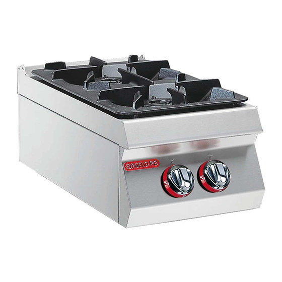
The open burner range, referred to from now on as the The appliance is produced in several versions to appliance, is designed and constructed for preparing meet varying user requirements (see diagram). and cooking foods in the professional catering sector. 0G0FA0 1G0FA0 2G0FA0 IDM-39603611300.tif Main Parts A)Hob: in stainless steel. - Page 6 TECHNICAL DATA See Connection card at back of manual. SAFETY DEVICES Although the appliance is complete with all safety de- vices, during installation and connection additional devices must be added if necessary to comply with the relevant legal requirements. The illustration shows the position of the devices. A)Gas supply tap: for turning the connection to the gas supply line on and off.
-
Page 7: Safety
SAFETY SAFETY REGULATIONS During design and construction, the constructor has manufacturer. Improper use of the appliance may in- paid special attention to factors which may cause volve health and safety risks and economic losses. risks to the health and safety of the people interacting All servicing operations requiring specific technical with the appliance. - Page 8 DESCRIPTION OF CONTROLS The appliance is fitted with the controls for use of its main Rear burner marker Front burner marker functions. Pilot light A)Top burner control marker Off marker knob; turns on and off and regulates the correspond- ing top burner. Full power Minimum power marker marker...
-
Page 9: Servicing
SERVICING RECOMMENDATIONS FOR SERVICING Keep the appliance at peak efficiency by carrying out pected health and safety hazards if turned on. the scheduled servicing procedures recommended At the end of each session of use and whenever by the constructor. Proper servicing will allow the best necessary, clean: performance, a longer working life and constant the hob (see page page 7);... -
Page 10: Fault
CHECKING GAS PRESSURE To carry out this operation, proceed as follows. 1 - Turn off the gas supply tap. 2 - Pull off the knob (A). 3 - Undo the screws (B) and remove the control panel (C). 4 - Undo the screw (D) of the pressure connection. -
Page 11: Handling And Installation
HANDLING AND INSTALLATION RECOMMENDATIONS FOR HANDLING AND INSTALLATION Important When handling and installing the appliance If necessary, the person authorised to carry comply with the information provided by out these operations must organise a "safe- the constructor directly on the packaging, ty plan"... - Page 12 INSTALLATION OF THE APPLIANCE All installation stages must be considered right from production of the general layout. Before starting these stages, as well as deciding the place of installation, if necessary, the person authorised to carry out these op- erations must organise a "safety plan" to protect the people directly involved, and he must also ensure strict compliance with all legal requirements, especially those relating to mobile work-sites.
- Page 13 GAS CONNECTION To make the connection, connect the mains line to the building codes, water supply regulations, appliance's connection pipe, fitting a shut-off tap (A), electrical wiring regulations, AS 5601/AG to allow the gas supply to be cut off when necessary. 601-Gas installations and any other statuto- ry regulations.
- Page 14 3b - Screw down the two screws 3 using the washer 4 , washer 5 and nuts 6 (see Fig. 3). 3c - Screw down the four screws 3 using the washer 4, washer 5 and nuts 6 (see Fig. 4). 0G0FA0 FIG. 2 1G0FA0 2G0FA0 FIG.
-
Page 15: Adjustments
ADJUSTMENTS RECOMMENDATIONS FOR ADJUSTMENTS Important Before making any type of adjustment, acti- In particular, turn off the gas supply tap and vate all the safety devices provided and de- prevent access to all devices which might cide whether staff at work and those in the cause unexpected health and safety hazards vicinity should be informed. -
Page 16: Replacing Parts
GREASING THE GAS TAP To carry out this operation, proceed as follows. 1 - Turn off the gas supply tap. 2 - Pull off the knobs (A). 3 - Undo the screws (B) and remove the control panel (C). 4 - Undo the screws (D) and extract the cap (E). - Page 17 REPLACING THE TOP BURNER PILOT LIGHT NOZZLE To carry out this operation, proceed as follows. 1 - Turn off the gas supply tap. 2 - Pull off the knob (A). 3 - Undo the screws (B) and remove the control panel (C).
-
Page 18: Annexes
- ANNEXES - Burner Total Gas consumption Model ø110 - 19.8 MJ/h ULPG 0G0FA0 N. 2 39.6 MJ/h 39.6 MJ/h 1G0FA0 N. 4 79.2 MJ/h 79.2 MJ/h 2G0FA0 N. 6 118.8 MJ/h 118.8 MJ/h - CONNECTION CARD (0G0FA0) - IDM-39603612700 copia.tif... - Page 19 - CONNECTION CARD (1G0FA0) - IDM-39603612800 copia.tif - CONNECTION CARD (2G0FA0) - IDM-39603612900 copia.tif...
- Page 20 - OPEN TOP BURNERS - N.G.C. (2) T.G.C. (3) Pilot Flame TPP (1) Supply pressure G.C. Ø (2.1) G.C. Ø (3.1) Ø (4) 1.13 kPa 19.8 MJ/h 2.00 mm 6.4 MJ/h 1.30 mm 0.35 mm 0.8 kPa ULPG 2.75 kPa 19.8 MJ/h 1.20 mm 6.4 MJ/h...
Need help?
Do you have a question about the 0G0FA0 and is the answer not in the manual?
Questions and answers