Table of Contents
Advertisement
Available languages
Available languages
Quick Links
Leggere attentamente le istruzioni prima di installare e utilizzare l'apparecchiatura.
Read the instructions carefully before installing and using the appliance.
Vor der Installation und Nutzung des Geräts müssen die Anleitungen aufmerksam durchgelesen werden.
Lire attentivement les instructions avant d'installer et d'utiliser l'appareil.
Léanse atentamente las instrucciones antes de instalar y utilizar el aparato.
Il mancato rispetto delle istruzioni fa decadere la garanzia del fabbricante.
In the event of failure to comply with the instructions, the manufacturer's warranty shall cease to apply.
Die Missachtung der Anleitungen hat den Verfall der vom Hersteller gewährten Garantie zur Folge.
Le non respect des instructions entraîne l'invalidation de la garantie du fabricant.
La inobservancia de las instrucciones provoca la invalidación de la garantía otorgada por el fabricante.
CUCINA FUOCHI APERTI
OPEN BURNER RANGE
GASHERD MIT OFFENEN FLAMMEN
CUISINIÈRE FEUX VIFS
COCINA FUEGOS ABIERTOS
MANUALE D'USO E INSTALLAZIONE
USE AND INSTALLATION MANUAL
BEDIEN- UND INSTALLATIONSHANDBUCH
MANUEL D'UTILISATION ET D'INSTALLATION
MANUAL DE USO E INSTALACIÓN
04WFAAV
08WFA4V
Italiano
English
Deutsch
Français
Español
Rev. 0
05/2019
3020561
IT
GB
DE
FR
ES
Advertisement
Chapters
Table of Contents

Subscribe to Our Youtube Channel
Related Manuals for Angelo Po 04WFAAV


Summary of Contents for Angelo Po 04WFAAV
- Page 1 Le non respect des instructions entraîne l'invalidation de la garantie du fabricant. La inobservancia de las instrucciones provoca la invalidación de la garantía otorgada por el fabricante. CUCINA FUOCHI APERTI OPEN BURNER RANGE 04WFAAV GASHERD MIT OFFENEN FLAMMEN 08WFA4V CUISINIÈRE FEUX VIFS COCINA FUEGOS ABIERTOS MANUALE D’USO E INSTALLAZIONE...
- Page 2 Cautela - Avvertenza Importante Non usare prodotti che contengono sostanze Verificare quotidianamente che i dispositivi dannose e pericolose per la salute delle per- di sicurezza siano perfettamente installati ed efficienti. sone (solventi, benzine, ecc.). Cautela - Avvertenza Cautela - Avvertenza La pavimentazione, in prossimità...
-
Page 3: Table Of Contents
INDICE rif. capitoli pag. 1 INFORMAZIONI GENERALI ..........2 2 INFORMAZIONI TECNICHE..........3 3 SICUREZZA................ 5 PARTE 4 USO E FUNZIONAMENTO..........6 5 MANUTENZIONI ..............8 6 GUASTI ................10 7 MOVIMENTAZIONE E INSTALLAZIONE ......11 8 REGOLAZIONI..............16 PARTE 9 SOSTITUZIONE PARTI ............ -
Page 4: Informazioni Generali
INFORMAZIONI GENERALI ISTRUZIONI E AVVERTENZE PER IL LETTORE Per rintracciare facilmente gli argomenti specifici di parte: contiene tutte le informazioni nec- essarie ai destinatari omogenei, cioè tutti gli interesse, consultare l’indice analitico posto all’in- operatori esperti e autorizzati a movimentare, izio del manuale. -
Page 5: Informazioni Tecniche
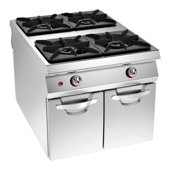
Per qualsiasi esigenza rivolgersi alle agenzie o alla Per ogni richiesta di assistenza tecnica, indi- sede centrale Angelo Po i cui riferimenti sono ripor- care i dati riportati sulla targhetta di identifi- tati nella sezione contatti del sito internet http:// cazione ed il tipo di difetto riscontrato. - Page 6 Organi principali A)Piano di cottura: realizzato in acciaio inox. B)Manopole comando bruciatori di piano: per re- golare l'alimentazione gas dei bruciatori. C)Bruciatori di piano: realizzati in ghisa smaltata, possono fornire potenze variabili in funzione del- la loro dimensione. D)Accensione piezoelettrica: per accendere il bruciatore.
-
Page 7: Sicurezza
F) Pericolo generico: richiama l'attenzione sul ris- G)Marcatura CE: indica che l’apparecchiatura è petto delle norme. “Si declina ogni responsabilità conforme a tutte le pertinenti disposizioni legisla- per il mancato rispetto delle norme di installazi- tive di prodotto applicabili. one e messa in funzione”. ACCESSORI A RICHIESTA A richiesta l'apparecchiatura può... -
Page 8: Uso E Funzionamento
Non lasciare oggetti o materiale infiammabile all'in- Cautela - Avvertenza terno del vano o in prossimità dell'apparecchiatura. La pavimentazione, in prossimità dell’appar- ecchiatura potrebbe essere scivolosa. Importante I collegamenti necessari (acqua, elettricità e gas) devono essere effettuati esclusiva- mente da personale adeguatamente spe- cializzato in conformità... - Page 9 ACCENSIONE E SPEGNIMENTO BRUCIATORI DI PIANO Accensione 1 - Aprire il rubinetto alimentazione gas. 2 - Premere e ruotare la manopola (A) in senso an- tiorario (pos. 1) e contemporaneamente mante- nere premuto il pulsante (B) per accendere la spia pilota. 3 - Mantenere premuta la manopola per circa 15 sec per consentire l'intervento della termocoppia.
-
Page 10: Manutenzioni
MANUTENZIONI ISTRUZIONI E AVVERTENZE PER LA MANUTENZIONE Mantenere l'apparecchiatura in condizioni di massi- pericolo inatteso causando danni alla sicurezza e alla salute delle persone. ma efficienza effettuando le operazioni di manuten- zione programmata previste dal Fabbricante. Una Ad ogni fine esercizio e ogni volta che se ne ris- buona manutenzione consentirà... - Page 11 PULIZIA PIANO DI COTTURA, BRUCIATORI E ACCESSORI Evitare che i componenti restino sporchi a lungo e quindi periodicamente, a seconda dell’intensità di lavoro (se necessario quotidianamente) procedere come di seguito indicato: 1 - Spegnere e lasciare raffreddare l’apparecchiat- ura. 2 - Smontare la griglia, lo spartifiamma (A) e il bru- ciatore (B).
-
Page 12: Guasti
Per qualsiasi esigenza rivolgersi alle agen- tificazione e correzione di eventuali anomalie e dis- zie o alla sede centrale Angelo Po i cui rifer- funzioni che potrebbero presentarsi in fase d'uso. imenti sono riportati nella sezione contatti Alcuni di questi problemi possono essere risolti del sito internet http://www.angelopo.com. -
Page 13: Movimentazione E Installazione
MOVIMENTAZIONE E INSTALLAZIONE ISTRUZIONI E AVVERTENZE PER LA MOVIMENTAZIONE E INSTALLAZIONE Importante Tutte le operazioni di movimentazione e di Colui che è autorizzato ad eseguire queste installazione dovranno essere eseguite nel operazioni dovrà, se necessario, organizza- rispetto della legislazione vigente in mate- re un “piano di sicurezza”... - Page 14 INSTALLAZIONE APPARECCHIATURA Tutte le fasi di installazione devono essere consid- erate sin dalla realizzazione del progetto generale. Prima di iniziare tali fasi, oltre alla definizione della zona di installazione, chi è autorizzato ad eseguire queste operazioni dovrà, se necessario, attuare un “piano di sicurezza”...
- Page 15 LIVELLAMENTO Agire sui piedi di appoggio (A) per livellare l'appar- ecchiatura. IDM-39610800800.tif MONTAGGIO APPARECCHIATURE IN BATTERIA Per montare le apparecchia- ture in batteria (fianco a fian- co) procedere nel modo indicato. 1 - Sfilare le manopole (A). 2 - Svitare le viti (C) e smontare cruscotti (B).
- Page 16 ALLACCIAMENTO GAS Importante Chi è autorizzato ad effettuare tale operazi- one deve possedere capacità ed esperienza acquisita e riconosciuta nel settore specifico, dovrà eseguire l'allacciamento a regola d'arte e tenere conto di tutti i requisiti normativi e legislativi. Ad allacciamento completato, pri- ma di rendere operativa l'attrezzatura, si dovrà...
- Page 17 3 - Svitare le viti (C) e smontare il cruscotto (D). Importante 4 - Svitare le viti (E) per smontare la scatola elettri- ca (F). In fase di allacciamento fare attenzione al 5 - Svitare le viti (G) per smontare il coperchio (H). collegamento dei cavi di neutro e di terra;...
-
Page 18: Regolazioni
COLLAUDO APPARECCHIATURA 3 - Verificare la regolare accensione e combus- tione dei bruciatori di piano. Importante 4 - Verificare e, se necessario, regolare la pres- Prima della messa in servizio, deve essere sione e la portata del gas al minimo e al massi- eseguito il collaudo dell'impianto, al fine di mo (vedi pag. - Page 19 REGOLAZIONE ARIA PRIMARIA BRUCIATORE DI PIANO (7 KW) Per questa operazione procedere nel modo indicato. 1 - Chiudere il rubinetto alimentazione gas. 2 - Sfilare le manopole (A). 3 - Svitare le viti (C) e smontare i cruscotti (B). 4 - Estrarre la vite (D). 5 - Regolare la posizione del supporto bruciatore (E) ad una distanza di 20 mm e avvitare la vite (D).
-
Page 20: Sostituzione Parti
SOSTITUZIONE PARTI ISTRUZIONI E AVVERTENZE PER LA SOSTITUZIONE PARTI Prima di effettuare qualsiasi intervento di persone. Qualora sia necessario sostituire dei sostituzione, attivare tutti i dispositivi di sicurez- componenti usurati, utilizzare esclusivamente za previsti e valutare se sia necessario infor- dei ricambi originali. - Page 21 SOSTITUZIONE UGELLO SPIA PILOTA BRUCIATORE DI PIANO Per questa operazione procedere nel modo indicato. 1 - Chiudere il rubinetto alimentazione gas. 2 - Sfilare le manopole (A). 3 - Svitare le viti (C) e smontare i cruscotti (B). 4 - Smontare il tubo (D). 5 - Estrarre l'ugello (E) e sostituirlo con quello adatto al tipo di gas utilizzato (vedi tabella in fondo al manuale).
- Page 22 Caution - warning Important Never use products containing substances Make a daily check that the safety devices harmful or hazardous for health (solvents, are properly installed and in good working order. Make a daily check that the safety petroleum spirits, etc.). devices are properly installed and in good working order.
- Page 23 CONTENTS ref. chapters page 1 GENERAL INFORMATION ..........2 2 TECHNICAL INFORMATION..........3 3 SAFETY ................5 PART 4 USE AND OPERATION ............6 5 SERVICING ............... 8 6 FAULTS ................10 7 HANDLING AND INSTALLATION ........11 8 ADJUSTMENTS ............... 16 PART 9 REPLACING PARTS ............
-
Page 24: General Information
GENERAL INFORMATION INSTRUCTIONS AND WARNINGS FOR THE READER To find the specific topics of interest to you quickly, part: contains all the information neces- refer to the index at the start of the manual. sary for special categories of reader, i.e. all This manual is subdivided into two parts. -
Page 25: Technical Information
For all requirements contact the agents or the head- When requesting service, state the data pro- quarters of Angelo Po which can be found in the vide on the nameplate and provide a descrip- contacts section of the website http://www.angelo- tion of the fault. - Page 26 Main Parts A)Hob: in stainless steel. B)Top burner control knobs: regulate the gas supply to the top burners. C)Top burners: in enamelled cast iron, the power they are able to supply varies depending on their size. D)Piezoelectric ignition: lights the burner. E)Hatches: for accessing the inside of the appli- ance.
-
Page 27: Safety
F) General hazard: all relevant regulations must be G)CE marking: indicates that the appliance is com- complied with. "Install in compliance with the rel- pliant with the relevant norms. evant regulations and use in well ventilated premises only". OPTIONAL ACCESSORIES The appliance can be equipped with the following accessories on request (“see general catalogue”). -
Page 28: Use And Operation
Caution - warning Important The floor, near the appliance, could be slip- The necessary connections (water, electric- pery. ity and gas) must be set up exclusively by suitably specialised staff , in accordance with local requirements. USE AND OPERATION INSTRUCTIONS AND WARNINGS FOR USE AND OPERATION Important Besides being authorised and appropriate- Before use, check that the safety devices... - Page 29 SWITCHING THE TOP BURNER ON AND OFF Lighting 1 - Turn on the gas supply tap. 2 - Press the knob (A) and turn it anti-clockwise (pos. 1), while keeping button (B) pressed, to light the pilot light. 3 - Keep the knob pressed for about 15 sec. to prime the thermocouple.
-
Page 30: Servicing
SERVICING INSTRUCTIONS AND WARNINGS FOR SERVICING Keep the appliance at peak efficiency by carrying At the end of each session of use and whenever out the scheduled servicing procedures recom- necessary, clean: mended by the manufacturer. Proper servicing will – The hob (see page 9). allow the best performance, a longer working life –... - Page 31 CLEANING THE HOB, BURNERS AND ACCESSORIES Avoid leaving the components dirty for long and, periodically,according to the intensity of work (if necessary daily),proceed as indicated below: 1-Switch the appliance off and leave it to cool. 2-Remove the grill, the burner cap (A) and the burner (B).
-
Page 32: Faults
For all requirements contact the agents or of any anomalies and malfunctions which might oc- the headquarters of Angelo Po which can cur during use. be found in the contacts section of the web- The user can solve some of these problems him- site http://www.angelopo.com. -
Page 33: Handling And Installation
HANDLING AND INSTALLATION INSTRUCTIONS AND WARNINGS FOR HANDLING AND INSTALLATION Important All handling and installation operations If necessary, the person authorised to carry should be carried out in accordance with out these operations must organise a "safe- current legislation on health and safety at ty plan"... - Page 34 INSTALLATION OF THE APPLIANCE All installation stages must be considered right from production of the general layout. Before starting these stages, as well as deciding the place of instal- lation, if necessary, the person authorised to carry out these operations must organise a "safety plan" to protect the people directly involved, and he must also ensure strict compliance with all legal require- ments, especially those relating to mobile work-...
- Page 35 LEVELLING Adjust the floor-mounted feet (A) to level the appli- ance. IDM-39610800800.tif ASSEMBLY APPLIANCES IN BANKS To assemble appliances in banks (side by side) proceed as described below. 1 - Pull off the knob (A). 2 - Undo the screws (C) and remove the control pan- els (B).
- Page 36 GAS, CONNECTION Important Those authorised to carry out this oper- ation must have experience acquired and certified in the specific sector, must make the connection to the proper standards, and must comply with all the relevant regulations and legislation. Once the connection has been made, before the appliance is put into opera- tion a general check must be made to ensure there are no gas leaks.
- Page 37 3 - Undo the screws (C) and remove the control panel (D). Important 4 - Undo the screws (E) to remove the electrical When connecting, take care over the con- equipment box (F). nection of the neutral and earth wires; if 5 - Undo the screws (G) to remove the lid (H).
-
Page 38: Adjustments
TESTING OF THE APPLIANCE 3 - Check that the hob burners are igniting correct- Important ly and their combustion. 4 - Check the gas pressure and flow-rate at mini- Before it is put into service, the system must mum and maximum settings and adjust if nec- be tested to check the operating conditions essary (see pages 9). - Page 39 ADJUSTING TOP BURNER PRIMARY AIR (7KW) To carry out this operation, proceed as follows. 1 - Turn off the gas supply tap. 2 - Pull off the knob (A). 3 - Undo the screws (C) and remove the control panels (B). 4 - Remove the screw (D).
-
Page 40: Replacing Parts
REPLACING PARTS INSTRUCTIONS AND WARNINGS FOR REPLACING PARTS Before carrying out any replacement procedure, ac- ponents due to the use of non original parts, or tivate all the safety devices provided and decide extraordinary work on the appliance which may whether staff at work and those in the vicinity modify the safety requirements without the manu- should be informed. - Page 41 REPLACING OVEN BURNER PILOT LIGHT NOZZLE To carry out this operation, proceed as follows. 1 - Turn off the gas supply tap. 2 - Pull off the knob (A). 3 - Undo the screws (C) and remove the control panels (B). 4 - Remove the pipe (D).
- Page 42 Vorsicht - Achtung Wichtig Verwenden Sie keine Produkte, die Stoff e enthalten, Stellen Sie jeden Tag durch Kontrollen welche für die menschliche Gesundheit schädlich und sicher, dass die Sicherheitsvorrichtungen fachgerecht installiert sind und einwand- gefährlich sind (Lösemittel, Benzin, usw.). frei funktionieren. Vorsicht - Achtung Vorsicht - Achtung Vor Ausführung irgendeines Eingriffs die...
- Page 43 INHALTSVERZEICHNIS Ref. Kapitel Seite 1 ALLGEMEINES..............2 2 TECHNISCHE INFORMATIONEN........3 3 SICHERHEIT ..............5 1. TEIL 4 GEBRAUCH UND BETRIEB..........6 5 WARTUNG................8 6 DEFEKTE................10 7 HANDHABUNG UND INSTALLATION ......11 8 EINSTELLUNGEN ............16 2. TEIL 9 AUSTAUSCH VON BAUTEILE .........
-
Page 44: Allgemeines
ALLGEMEINES ANWEISUNGEN UND WARNHINWEISE FÜR DEN LESER Konsultieren Sie das Sachregister, das am Anfang des 2. Teil: Diese Informationen wenden sich an eine Handbuchs zu finden ist, um leichter unter bestimmten bestimmte Zielgruppe. Sie sind für erfahrene Bedi- Themen von besonderem Interesse nachschlagen zu ener bestimmt, die für Handhabung, Transport, In- können. -
Page 45: Technische Informationen
Das Gerät wird bedarfsabhängig in ver- projektiert und konstruiert. Das Gerät hat zwei Ar- schiedenen Versionen hergestellt (siehe beitsfronten und kann daher in der Raummitte auf- Abbildung). gestellt werden. 04WFAAV 08WFA4V 10 kW 7 kW 7 kW 10 kW 7 kW 10 kW IDM-39610800100_08WFA4V.tif... - Page 46 Hauptorgane A)Kochmulde: aus Edelstahl. B)Schalter der Kochstellenbrenner: zum Einstel- len der Heizleistung der Kochstellenbrenner C)Kochstellenbrenner: aus emailliertem Gusseis- en, Heizleistung von Größe abhängig D)Piezozünder: zum Zünden des Brenners E)Türen: für den Zugang zum Innenbereich der Schränke. F) Gasanschluss: für den Anschluss der Gaszu- fuhr IDM-39610800200.tif TECHNISCHE DATEN...
-
Page 47: Sicherheit
F) Allgemeine Gefahr: Fordert zur Beachtung der G)CE-Kennzeichnung: Es weist darauf hin, dass Vorschriften auf. "Im Falle der Missachtung der das Gerät alle für das Produkt anwendbaren, ein- Vorschriften für die Installation und Inbetrieb- schlägigen gesetzlichen Vorschriften erfüllt. nahme wird keine Haftung übernommen." OPTIONALES ZUBEHÖR Auf Wunsch kann das Gerät mit folgenden Zube- hörteilen ausgestattet werden (“siehe Hauptkatalog”). -
Page 48: Gebrauch Und Betrieb
Beim täglichen Gebrauch des Geräts ist die ständige Vorsicht - Achtung Anwesenheit des Bedienungspersonals erforderlich. Der Boden in der Nähe des Gerätes könnte rutschig Beim Waschen des Geräts den Wasserstrahl nicht sein. direkt auf die inneren Teile des Geräts richten. Keine entzündlichen Gegenstände oder Materialien im Wichtig Schrank oder in der Nähe des Geräts aufbewahren. - Page 49 EIN- UND AUSSCHALTEN DER KOCHSTELLENBRENNER Zündung 1 - Öffnen Sie den Gashahn. 2 - Schalter (A) niederdrücken und entgegen dem Uhrzeigersinn drehen (Pos. 1); gleichzeitig die Taste (B) zum Zünden des Zündflammenbren- ners gedrückt halten. 3 - Halten Bedienknebel etwa Sekunden lang gedrückt, damit das Thermoele- ment in Aktion treten kann.
-
Page 50: Wartung
WARTUNG ANWEISUNGEN UND WARNHINWEISE FÜR DIE WARTUNG Sorgen Sie dafür, dass das Gerät im Zustand maxi- situationen führen und die Sicherheit und der maler Leistungsfähigkeit bleibt, indem Sie die vom Gesundheit von Personen beeinträchtigen Hersteller vorgesehenen planmäßigen Wartungsar- könnten. beiten ausführen. Gute Wartung zahlt sich durch opti- Folgende Elemente sind nach jedem Einsatz und male Leistungen, längere Betriebsdauer und eine bei Bedarf zu reinigen:... - Page 51 REINIGUNG DER KOCHMULDE, BRENNER UND ZUBEHÖRTEILE Es ist zu vermeiden, dass die Bauteile für längere Zeit verschmutzt bleiben, deshalb je nach Anwend- ung (ggf. auch täglich) wie nachfolgend beschrie- ben vorgehen. 1-.Das Gerät ausschalten und abkühlen lassen. 2-.Den Rost, den Brennerdeckel (A) und den Brenner (B) abbauen.
-
Page 52: Defekte
Bei Rückfragen wenden Sie sich bitte an helfen, eventuelle Anomalien oder Funktions- die Handelsvertretungen oder den Haupt- störungen, die während des Betriebs auftreten kön- sitz des Unternehmens Angelo Po, die nen, aufzufinden und zu beheben. entsprechenden Kontaktdaten sind auf der Einige dieser Probleme können vom Benutzer Webseite http://www.angelopo.com unter... -
Page 53: Handhabung Und Installation
HANDHABUNG UND INSTALLATION ANWEISUNGEN UND WARNHINWEISE FÜR DIE INSTALLATION UND HANDHABUNG Wichtig Alle Transport- und Aufstellungsarbeiten Die für diese Operationen autorisierte Per- müssen unter Berücksichtigung der gel- son wird bei Bedarf einen "Sicherheitsp- tenden gesetzlichen Vorschriften zur Ge- lan" aufstellen müssen, sundheit und Sicherheit am Arbeitsplatz Unversehrtheit der direkt an dem Vorgang... - Page 54 INSTALLATION DES GERÄTS Es müssen sämtliche Phasen der Installation, schon von der Umsetzung des allgemeinen Projekts an, berücksichtigt werden. Die für diese Operationen autor- isierte Person wird vor Einleitung dieser Phasen den In- stallationsstandort bestimmen und bei Bedarf einen "Sicherheitsplan" aufstellen, um die Unversehrtheit der direkt am Vorgang beteiligten Personen zu gewähr- leisten und die gesetzlichen Bestimmungen zu befol- gen.
- Page 55 NIVELLIEREN Regulieren Sie die Füße (A), um das Gerät wasser- waagengerecht aufzustellen. IDM-39610800800.tif MONTAGE BEI REIHENAUFSTELLUNG Verfahren folgender- maßen, um Geräte (nebe- neinander) in einer Reihe aufzustellen. 1 - Den Schalter (A) abzie- hen. 2 - Die Schrauben (C) auss- chrauben und die Blend- en (B) ausbauen.
- Page 56 GASANSCHLUSS Wichtig Diese Arbeit darf nur von zugelassenen und erfahrenen Fachleuten ausgeführt werden. Der Anschluss muss fachgerecht und vor- schriftsmäßig ausgeführt werden und allen einschlägigen gesetzlichen Bestimmungen entsprechen. Nach Ausführung des An- schlusses muss vor der Inbetriebnahme des Geräts durch eine allgemeine Kontrolle...
- Page 57 3 - Drehen Sie die Schrauben (C) heraus und H05RN-F erfüllen müssen. montieren Sie die Blende (D) ab. 4 - Die Schrauben (E) lösen, um die An- Wichtig schlussdose (F) auszubauen. Bei der Ausführung des Anschlusses auf 5 - Die Schrauben (G) lösen, um den Deckel (H) ab- den Anschluss des Neutral- und des Schut- zunehmen.
-
Page 58: Einstellungen
TESTLAUF ZUR ABNAHME DES GERÄTS 3 - Sicherstellen, dass Zündung und Verbrennung der Kochstellenbrenner ordnungsgemäß erfol- Wichtig gen. Vor der Inbetriebnahme muss ein Testlauf 4 - Überprüfen Sie Gasdruck und -durchsatz bei mini- der Anlage durchgeführt werden, um den maler und maximaler Zufuhr und regulieren Sie, Betriebszustand jeder einzelnen Komponen- falls notwendig, die Einstellungen (siehe S. - Page 59 EINSTELLUNG DER PRIMÄRLUFT DES KOCHSTELLENBRENNERS (7 KW) Für diesen Vorgang in der angegebenen Weise verfahren. 1 - Schließen Sie den Gashahn. 2 - Den Schalter (A) abziehen. 3 - Die Schrauben (C) ausschrauben und die Blenden (B) ausbauen. 4 - Die Schraube (D) entfernen. 5 - Die Stellung der Brennerhalterung (E) auf einen Abstand von 20 mm einstellen und die Schraube (D) anziehen.
-
Page 60: Austausch Von Bauteile
AUSTAUSCH VON BAUTEILE ANWEISUNGEN UND WARNHINWEISE FÜR DAS AUSWECHSELN VON BAUTEILEN Vor jedem Eingriff zur Ersetzung eines Teils müs- Komponenten, die Verschleißerscheinungen zei- sen sämtliche vorgesehenen Sicherheitsvorrichtun- gen; verwenden Sie dabei ausschließlich Original- gen aktiviert werden. Überlegen Sie, ob es ersatzteile.Es wird jede Haftung für Personen- oder notwendig ist, das arbeitende Personal und die in Komponentenschäden abgelehnt, die entstehen,... - Page 61 AUSTAUSCH DER DÜSE DES ZÜNDFLAMMENBRENNERS DES KOCHSTELLENBRENNERS Für diesen Vorgang in der angegebenen Weise verfahren. 1 - Schließen Sie den Gashahn. 2 - Den Schalter (A) abziehen. 3 - Die Schrauben (C) ausschrauben und die Blenden (B) ausbauen. 4 - Den Schlauch (D) ausbauen. 5 - Nehmen Sie die Düse (E) heraus und ersetzen Sie sie mit dem für den betreffenden Gastyp geeigneten Bauteil (siehe Tabelle am Ende des...
- Page 62 Attention Important Ne pas utiliser de produits qui contiennent des sub- Vérifier quotidiennement que les disposi- stances dangereuses pour la santé des personnes tifs de sécurité soient parfaitement instal- lés et efficaces. (solvants, essences, etc.). Attention Attention Le sol, à proximité de l’appareil, pourrait être Avant toute intervention, couper l’alimenta- glissant.
- Page 63 INDEX réf. chapitres page 1 INFORMATIONS GENERALES.......... 2 2 INFORMATIONS TECHNIQUES ........3 3 SÉCURITÉ ................5 PARTIE 4 UTILISATION ET FONCTIONNEMENT ......6 5 ENTRETIEN................ 7 6 PANNES ................10 7 MANUTENTION ET INSTALLATION........ 11 8 RÉGLAGES ..............16 PARTIE 9 REMPLACEMENT DE PIÈCES ........
- Page 64 INFORMATIONS GENERALES INSTRUCTIONS ET AVERTISSEMENTS POUR LE LECTEUR Pour retrouver facilement les sujets qui vous in- partie: elle contient toutes les informations téressent, consulter l’index analytique au début du nécessaires aux destinataires homogènes, manuel. c’est-à-dire tous les opérateurs experts et au- Ce manuel est divisé...
- Page 65 DEMANDE D’ASSISTANCE Pour toute exigence, s’adresser aux agences ou au Pour toute demande d’assistance technique, siège centra Angelo Po dont les références sont re- indiquer les données reportées sur la plaque portées dans la section contacts du site internet ht- d’identification et le type de défaut relevé.
- Page 66 Organes principaux A)Plan de travail: en acier inox B)Manettes de commande des brûleurs fourneau: pour régler l’alimentation du gaz des brûleurs. C)Brûleurs fourneau: en fonte émaillée, ils peu- vent fournir des puissances variables en fonction de leur dimension. D)Allumage piézoélectrique: pour allumer le brû- leur E)Portes: pour accéder à...
- Page 67 F) Risque générique : rappelle l’attention sur le re- G)Marquage CE: indique que l’équipement est spect des normes. « Installer conformément aux conforme à toutes les dispositions législatives normes en vigueur et n’utiliser que dans des pertinentes pour les produits applicables. pièces bien aérées ».
- Page 68 Pendant le lavage de l’appareil ne pas diriger de Important jets d’eau sous pression sur les pièces intérieures. Les raccordements nécessaires (eau, électricité et Ne pas laisser d’objets ou de matériau inflammable gaz) doivent être effectués exclusivement par du per- à...
- Page 69 ALLUMAGE ET EXTINCTION BRÛLEURS FOURNEAU Allumage 1 - Ouvrir le robinet d’alimentation du gaz. 2 - Pousser et tourner la manette (A) en sens anti- horaire (pos. 1) et simultanément tenir pressé le bouton (B) pour allumer la veilleuse pilote. 3 - Tenir pressée la manette pendant environ 15 sec pour permettre l'intervention du thermocou- ple.
- Page 70 ENTRETIEN INSTRUCTIONS ET AVERTISSEMENTS POUR L’ENTRETIEN Maintenir l’appareil en parfait état de fonctionne- ger inattendu pour la sécurité et la santé des ment en effectuant les opérations d’entretien pro- personnes. grammé prévues par le fabricant. Un bon entretien Après chaque utilisation et lorsque cela s’avère permettra d’obtenir les meilleures performances, nécessaire, nettoyer: une plus longue durée et un maintien constant des...
- Page 71 NETTOYAGE DE LA TABLE DE CUISSON, DES BRÛLEURS ET DES ACCESSOIRES Éviter que les composants restent longtemps sales puis périodiquement, selon l’intensité du travail (si nécessaire quotidiennement) procéder comme in- diqué ci-après: 1-Éteindre et laisser l’équipement refroidir. 2-Démonter la grille, le couvercle (A) et le brûleur (B).
- Page 72 à l'identification et à la correction d’éven- Pour toute exigence, s’adresser aux agences ou au tuels pannes et dysfonctionnements qui pourraient siège centra Angelo Po dont les références sont re- se présenter en cours d’utilisation. portées dans la section contacts du site internet ht- Certains de ces problèmes peuvent être résolus par...
- Page 73 MANUTENTION ET INSTALLATION INSTRUCTIONS ET AVERTISSEMENTS POUR LA MANUTENTION ET L’INSTALLATION Important Toutes les opérations de déplacement et Celui qui est autorisé à effectuer ces opéra- d’installation devront être effectuées dans tions devra, si nécessaire, organiser un le respect de la législation en vigueur en “plan de sécurité”...
- Page 74 MISE EN PLACE DE L’APPAREIL Toutes les phases de mise en place doivent être prises en considération, dès la réalisation du projet général. Avant de commencer ces phases, outre la définition de la zone de mise en place, celui qui est autorisé à effec- tuer ces opérations devra, si nécessaire, faire un “plan de sécurité”...
- Page 75 MISE À NIVEAU Agir sur les pieds d’appui (A) pour mettre de niveau l’appareil. IDM-39610800800.tif MONTAGE DES APPAREILS EN BATTERIE Pour monter les appareils en batterie (les uns à côté des autres), procéder comme suit. 1 - Enlever la manette (A). 2 - Dévisser les vis (C) et démonter les tableaux de commandes (B).
- Page 76 RACCORDEMENT DU GAZ Important La personne autorisée à effectuer cette opération devra avoir les capacités et l’ex- périence acquise et reconnue dans le sect- eur spécifique ; elle devra effectuer le raccordement dans les règles de l’art et te- nir compte de toutes les exigences im- posées par les normes et les lois.
- Page 77 2 - Enlever la manette (B). 3 - Dévisser les vis (C) et démonter le tableau de Important commandes (D). Au moment du branchement, faire attention 4 - Dévisser les vis (E) et démonter le boîtier élec- à la connexion des câbles de neutre et de trique (F).
- Page 78 ESSAI DE L’APPAREIL 3 - Vérifier l’allumage régulier et la combustion des brûleurs de table. Important 4 - Vérifier et, si nécessaire, régler la pression et le Avant la mise en service, l’essai de l’installa- débit du gaz au minimum et au maximum (voir tion doit être fait pour évaluer les conditions page 9);...
- Page 79 RÉGLAGE DE L’AIR PRIMAIRE DU BRÛLEUR FOURNEAU (7KW) Pour cette opération, procéder comme suit. 1 - Fermer le robinet d’alimentation du gaz. 2 - Enlever la manette (A). 3 - Dévisser les vis (C) et démonter les tableaux de commandes (B). 4 - Extraire la vis (D).
- Page 80 REMPLACEMENT DE PIÈCES INSTRUCTIONS ET AVERTISSEMENTS POUR LE REMPLACEMENT DES PIÈCES Avant d’effectuer tout remplacement, activer tous change d’origine.Le fabricant décline toute respon- les dispositifs de sécurité prévus et évaluer s’il faut sabilité pour des dommages à des personnes ou à informer les opérateurs travaillant sur l'appareil et des composants dérivant de l’utilisation de pièces ceux à...
- Page 81 REMPLACEMENT DE LA BUSE VEILLEUSE PILOTE DU BRÛLEUR FOURNEAU Pour cette opération, procéder comme suit. 1 - Fermer le robinet d’alimentation du gaz. 2 - Enlever la manette (A). 3 - Dévisser les vis (C) et démonter les tableaux de commandes (B).
- Page 82 Precaución - advertencia Importante No usar productos que contengan sustancias nocivas Controlar periódicamente que los equipos y/o peligrosas para la salud de las personas (disol- de seguridad se encuentren en perfecto es- tado y estén correctamente instalados. ventes, bencinas, etc.). Precaución - advertencia Precaución - advertencia El pavimento, cerca del equipo, podría ser...
- Page 83 ÍNDICE ref. capítulos pág 1 INFORMACIONES DE CARÁCTER GENERAL ....2 2 INFORMACIONES DE CARÁCTER TÉCNICO ....3 3 SEGURIDAD ............... 5 PARTE 4 USO Y FUNCIONAMIENTO ..........6 5 MANTENIMIENTO .............. 8 6 AVERÍAS................10 7 DESPLAZAMIENTO Y INSTALACIÓN ......11 8 REGULACIONES .............
-
Page 84: Informaciones De Carácter General
INFORMACIONES DE CARÁCTER GENERAL INSTRUCCIONES Y ADVERTENCIAS PARA EL LECTOR Para ubicar fácilmente los temas específicos de in- parte: contiene todas las informaciones terés, consúltese el índice analítico que se encuentra necesarias para destinatarios homogéneos, al inicio del manual. esto es, todos los operadores expertos y autor- Este manual comprende dos partes. -
Page 85: Informaciones De Carácter Técnico
Para cualquier necesidad, diríjase a las agencias o Para solicitar asistencia técnica deberán indic- a la sede central de Angelo Po, cuyos referentes se arse los datos reproducidos en la placa de indican en la sección de contactos del sitio web ht- identificación y el tipo de desperfecto que se... - Page 86 Órganos principales A)Encimera: fabricada en acero inox B)Mandos de control quemadores de plano: para regular la alimentación de gas de los quemadores C)Quemadores de plano: realizados en fundición es- maltada, pueden proporcionar potencias variables en función de sus dimensiones D)Encendido piezoeléctrico: para encender el que- mador E)Portezuelas: para obtener acceso a los compar- timientos...
-
Page 87: Seguridad
F) Peligro genérico: tiene por objeto recordar la G)Aprobación CE: indica que el aparato es con- necesidad de respetar las normas. “Instalar en forme con todas las disposiciones legislativas conformidad con lo dispuesto por la normativa vi- pertinentes de producto aplicables. gente y utilizar sólo en ambientes adecuadamente aireados”. -
Page 88: Uso Y Funcionamiento
Durante el lavado del aparato no dirigir chorros de Importante agua a presión hacia sus partes internas. No dejar objetos o material inflamable en el interior Las conexiones necesarias (agua, electrici- del compartimiento ni en proximidad del aparato. dad y gas) se deben realizar exclusiva- mente por el personal especializado de Precaución - advertencia manera adecuada y de acuerdo con las dis-... - Page 89 ENCENDIDO Y APAGADO QUEMADORES DE PLANO Encendido 1 - Abrir el grifo de alimentación del gas. 2 - Presionar y hacer girar el mando (A) en sentido antihorario (pos. 1) manteniendo simultánea- mente presionado el botón (B) para encender el piloto. 3 - Mantener presionado el mando durante unos 15 s a fin de permitir la intervención del termopar.
-
Page 90: Mantenimiento
MANTENIMIENTO INSTRUCCIONES Y ADVERTENCIAS PARA EL MANTENIMIENTO Mantener el equipo en condiciones de máximo ser activados, podrían provocar situaciones de peligro, con reducción de la seguridad y rendimiento, efectuando las operaciones de man- riesgo para la salud de las personas. tenimiento programado previstas por el fabricante. - Page 91 LIMPIEZA DE ENCIMERA, QUEMADORES Y ACCESORIOS Evite que los componentes se queden sucios du- rante mucho tiempo y después periódicamente, según la intensidad de trabajo (si fuera necesario todos los días) proceda a hacer lo siguiente: 1 - Apague y deje enfriar el equipo. 2 - Desmonte la rejilla, el difusor (A) y el quemador (B).
-
Page 92: Averías
Para cualquier necesidad, diríjase a las Las siguientes informaciones tienen por objeto fa- agencias o a la sede central de Angelo Po, cilitar la identificación y corrección de eventuales cuyos referentes se indican en la sección anomalías y disfunciones que podrían presentarse... -
Page 93: Desplazamiento Y Instalación
DESPLAZAMIENTO Y INSTALACIÓN INSTRUCCIONES Y ADVERTENCIAS PARA EL DESPLAZAMIENTO Y LA INSTALACIÓN Importante Todas las operaciones de movimiento e insta- La persona autorizada para efectuar estas op- lación tendrán que realizarse respetando la eraciones deberá, si fuera necesario, organi- legislación vigente en materia de salud y seg- zar un "plan de seguridad", a fin de uridad en el trabajo. - Page 94 INSTALACIÓN DEL EQUIPO Durante la realización del proyecto general, deben ser consideradas todas las fases de la instalación. Antes de comenzar dichas fases, además de establecer la zona de instalación, la persona autorizada a efectuar estas operaciones deberá, si fuera necesario, aplicar un "plan de seguridad"...
- Page 95 NIVELACIÓN Operar con las patas de apoyo (A) para nivelar el equipo. IDM-39610800800.tif MONTAJE DE EQUIPOS EN BATERÍA Para montar los equipos en batería (uno al lado del otro) aplicar las siguientes in- strucciones. 1 - Retire el mando (A). 2 - Desenroscar los tornillos (C) y desmontar los pan- eles de mando (B).
- Page 96 ENLACE GAS Importante El personal autorizado para ejecutar esta operación debe poseer capacidad y haber adquirido experiencia efectiva en el sector específico; la conexión deberá ejecutarse respetando rigurosamente todos los req- uisitos establecidos por las normativas vi- gentes. Una vez efectuada la conexión, antes de poner en funcionamiento el apara- to se deberá...
- Page 97 3 - Desenroscar los tornillos (C) y desmontar el ta- blero de instrumentos (D). Importante 4 - Desenroscar los tornillos (E) y desmontar la Durante las operaciones de enlace se de- caja eléctrica (F). berá prestar especial atención a la conex- 5 - Desenroscar los tornillos (G) y desmontar la ión de los cables de neutro y de tierra ya tapa (H).
-
Page 98: Regulaciones
PRUEBA DE FUNCIONAMIENTO DEL EQUIPO la respectiva transformación (véase pág. 3 - Controlar el encendido y la combustión de los que- Importante madores de la encimera. Antes de la puesta en servicio debe efectuarse 4 - Controlar y, si fuera necesario, regular la presión y la prueba de funcionamiento del sistema, a fin el caudal del gas al mínimo y al máximo (véase de evaluar las condiciones operativas de cada... - Page 99 REGULACIÓN AIRE PRIMARIO QUEMADOR DE PLANO (7KW) Para efectuar esta operación, aplicar las siguientes instrucciones. 1 - Cerrar el grifo de alimentación del gas. 2 - Retire el mando (A). 3 - Desenroscar los tornillos (C) y desmontar los paneles de mando (B). 4 - Extraer el tornillo (D).
- Page 100 SUSTITUCIONE DE PIEZAS INSTRUCCIONES Y ADVERTENCIAS PARA LA SUSTITUCIÓN DE LAS PIEZAS Antes de efectuar cualquiera operación de sus- se deberán utilizar exclusivamente piezas de re- titución, activar todos los dispositivos de seguridad cambio originales. Se declina toda responsabilidad previstos y evaluar la conveniencia de informar por daños a personas o a componentes del equipo adecuadamente tanto al personal operativo como derivados del empleo de piezas de recambio no...
- Page 101 SUSTITUCIÓN INYECTOR TESTIGO PILOTO QUEMADOR DE PLANO Para efectuar esta operación, aplicar las siguientes instrucciones. 1 - Cerrar el grifo de alimentación del gas. 2 - Retire el mando (A). 3 - Desenroscar los tornillos (C) y desmontar los paneles de mando (B). 4 - Retire el tubo (D).
- Page 102 Branchement électrique Con- Ø110 - 7 Kw Ø130 - 10 Kw G25.3 exión eléctrica (Min. 2,3 Kw) (Min. 2,5/3,2 Kw) G25.1 0,6W/230V1~N 04WFAAV N. 1 N. 1 1,80 m 2,09 m 2,09 m 1,34 Kg/h 1,32 Kg/h 50/60 Hz SCHEDA ALLACCIAMENTI - CONNECTION CARD - ANSCHLUSSSCHEMA FICHE DES RACCORDEMENTS - FICHA DE ENLACES IDM-39610802501.tif...
- Page 103 Bruciatori Consumo gas Allacciamento elettrico Burner - Brenner Gas consumption - Gasverbrauch Modello Electrical connection Stro- Consommation de gaz - Consumo de gas Bruleur - Quemadores Model - Modelle manschluss Modèle - Modelo Branchement électrique Con- Ø110 - 7 Kw Ø130 - 10 Kw G25.3 exión eléctrica...
- Page 104 1) Morsettiera - Terminal board - Klemmenbrett - Plaque à bornes - Regleta de conexión 3) Gruppo accensione - Ignition unit - Baugruppe Zündung - Groupe d’allumage - Unidad de 04WFAAV 2) Pulsante accensione - Ignition button - Taste Zündung - Bouton d’allumage - Botón de encendido 4) Candeletta anteriore - Front plug - Vordere Zündkerze - Bougie avant - Bujía delantera...
- Page 105 Tabella iniettori bruciatore di piano ø110 - Table of top burner injectors ø110 - Tabelle: Düsen für Kochstellenbrenner ø110 Tableau des injecteurs du brûleur fourneau ø110 - Tabla inyectores quemador de plano ø110 ø (4) ø (5) ø (6) ø (8) p (3) mbar p (7) mbar Pen mbar...
- Page 106 Tabella iniettori bruciatore di piano ø110 - Table of top burner injectors ø110 - Tabelle: Düsen für Kochstellenbrenner ø110 Tableau des injecteurs du brûleur fourneau ø110 - Tabla inyectores quemador de plano ø110 ø (4) ø (5) ø (6) ø (8) p (3) mbar p (7) mbar Pen mbar...
- Page 107 Tabella iniettori bruciatore di piano ø110 - Table of top burner injectors ø110 - Tabelle: Düsen für Kochstellenbrenner ø110 Tableau des injecteurs du brûleur fourneau ø110 - Tabla inyectores quemador de plano ø110 ø (4) ø (5) ø (6) ø (8) p (3) mbar p (7) mbar Pen mbar...
- Page 108 Tabella iniettori bruciatore di piano ø130 - Table of top burner injectors ø130 - Tabelle: Düsen für Kochstellenbrenner ø130 Tableau des injecteurs du brûleur fourneau ø130 - Tabla inyectores quemador de plano ø130 ø (4) ø (5) ø (6) ø (8) p (3) mbar p (7) mbar Pen mbar...
- Page 109 Tabella iniettori bruciatore di piano ø130 - Table of top burner injectors ø130 - Tabelle: Düsen für Kochstellenbrenner ø130 Tableau des injecteurs du brûleur fourneau ø130 - Tabla inyectores quemador de plano ø130 ø (4) ø (5) ø (6) ø (8) p (3) mbar p (7) mbar Pen mbar...
- Page 110 Tabella iniettori bruciatore di piano ø130 - Table of top burner injectors ø130 - Tabelle: Düsen für Kochstellenbrenner ø130 Tableau des injecteurs du brûleur fourneau ø130 - Tabla inyectores quemador de plano ø130 ø (4) ø (5) ø (6) ø (8) p (3) mbar p (7) mbar Pen mbar...
- Page 111 Tabella caratteristiche gas - Table of gas characteristics - Tabelle der Gas-Eigenschaften Tableau des caractéristiques du gaz - Tabla características gas Potere calorifero inferiore (Hi) Famiglia Tipo di gas Indice Wobbe (MJ/m Net calorific value (Hi) Group Gas type Wobbe index (MJ/m Unterer Heizwert (Hi) Familie Gastypen...
- Page 112 Angelo Po Grandi Cucine S.p.A. con socio unico - Sede Centrale s.s. Romana Sud 90/F - 41012 Carpi (Mo) - Italy Tel: +39 059 639411 Fax: +39 059 642499 www.angelopo.com IT - È vietata la riproduzione, anche parziale, di questo documento senza il consenso del fabbricante. Egli è impegnato in una politica di continuo mi- glioramento e si riserva il diritto di modifi care questa documentazione senza l’obbligo di preavviso purché...
Need help?
Do you have a question about the 04WFAAV and is the answer not in the manual?
Questions and answers