
Subscribe to Our Youtube Channel
Related Manuals for Zumtobel ONLITE local SB 128 Controller


Summary of Contents for Zumtobel ONLITE local SB 128 Controller
- Page 1 ONLITE local SB 128 Controller Operating instructions with quick commissioning guide and installation check list Art. No.: 00072417...
-
Page 3: Table Of Contents
2.5.2 DALI bus .................... 13 Installation......................14 Who is allowed to perform the installation? ..........14 Mounting the ONLITE local SB 128 Controller ..........14 Connecting the DALI bus ................15 Connecting the ONLITE local Switch module ..........16 Connecting a GSM module ................17 Connecting a remote display device ............ - Page 4 12.2 Luminaire cannot be found during re-initialisation or system extension..62 12.3 Luminaire is reporting communication error during operation...... 64 12.4 Luminaire is reporting lamp error during operation ........65 12.5 Luminaire is reporting battery error .............. 66 ONLITE local SB 128 Controller...
- Page 5 12.6 Luminaire is reporting charging error ............66 12.7 Various SB 128 error messages ..............67 ONLITE local SB 128 Controller...
- Page 6 ONLITE local SB 128 Controller...
-
Page 7: Copyright
+43 (0) 5572 390-0 Validity and technical state of this manual This operating manual only relates to devices of the type ONLITE local SB 128 Controller with the article number 22 156 829. Technical modifications made after printing this manual are not considered. Subject to changes. -
Page 8: Notes Regarding Security And Use Of The Operating Instructions
This symbol points to sources of danger which may cause personal injuries or severe damages to system components. Danger! This symbol points to sources of danger which may cause critical personal injuries or acute damages to system components. ONLITE local SB 128 Controller... -
Page 9: Important Notes Regarding Industrial And Operational Safety
Illustrations and circuit diagrams in these installation and operating instructions are partly for demonstration purposes only. Drawings and plans that were especially created for the lighting system and are in accordance with local requirements must be observed. ONLITE local SB 128 Controller... -
Page 10: Product Description
Product description Specified use The ONLITE local SB 128 Controller is intended for central controlling and monitoring of emergency lighting systems. Parameterisation and operation of the system is restricted to authorised technical staff. Personal danger may occur in case of •... -
Page 11: Description
600 m. All settings of the ONLITE local SB 128 Controller are stored to a non-volatile memory. Due to this, the settings will not get lost even if the device is completely switched off. Via the infrared interface on the controller’s front panel, a PC or a PDA can be connected. -
Page 12: Example Circuit Diagram
Example circuit diagram Figure 1: Example circuit diagram of the ONLITE local check system ONLITE local SB 128 Controller... -
Page 13: Technical Data
Technical Data Item name Designation: ONLITE local SB 128 Controller Art.-No.: 22.156.829 Power supply Supply voltage: 230 V AC ± 10 % Mains frequency: 50 to 60 Hz Power consumption: 10 W max. Connections Connections: Mains, 2 x DALI, 3 potential-free signaling contacts,... -
Page 14: Communication And Data Exchange
Communication and data exchange interfaces IR interface The IR interface located on the ONLITE local SB 128 Controller front panel establishes a direct connection to the ONLITE IR-Printer or to an external PC (e.g. a Notebook). Via this interface, the current configuration data as well as the test logs can be read out. -
Page 15: Dali Bus
ONLITE local check system through the DALI bus The possibly available general lighting connected to the same bus is not affected by the ONLITE local SB 128 Controller and can be controlled using an EMOTION Touch module or LM-DALI, for instance. -
Page 16: Installation
Mounting the ONLITE local SB 128 Controller The ONLITE local SB 128 Controller can be mounted using the drilling holes in the rear panel or on a top-hat rail according to EN 50022. The required drilling hole distances can be found in the accompanying drawing. -
Page 17: Connecting The Dali Bus
• 150 m - 200 m 1.0 mm • 200 m - 300 m 1.5 mm Recommendation: Always use a line cross section of 1.5 mm Figure 5: Creating a DALI connection with the ONLITE SB 128 Controller ONLITE local SB 128 Controller... -
Page 18: Connecting The Onlite Local Switch Module
SB 128 Controller. It provides four switching inputs (S1 to S4) which can be used for an individual switching of security luminaires and/or emergency exit sign luminaires. The push button inputs may only be operated potential-free. Figure 6: Connecting the ONLITE local Switch module to the ONLITE local SB 128 Controller ONLITE local SB 128 Controller... -
Page 19: Connecting A Gsm Module
SB 128 Controller using the buttons of a tone-dialling telephone. Warning! Prior to clamping, both the ONLITE local SB 128 Controller and the device to be connected must be switched dead. The ONLITE GSM Module is connected to the controller's RS 232 interface as follows: Connect the RS 232 cable to the terminals Rx, Tx and Gnd of the ONLITE local SB 128 Controller. - Page 20 Figure 8: Connecting the ONLITE GSM module to the ONLITE local SB 128 Controller ONLITE local SB 128 Controller...
-
Page 21: Connecting A Remote Display Device
K31-K34 NO K31-K32 NC NO: normally open NC: normally closed • the contact rating: max. voltage: 10 - 30 V AC/DC max. current: • the plans and drawings according to the conditions at the installation site. ONLITE local SB 128 Controller... - Page 22 Figure 9: Connecting the ONLITE local remote interface to the ONLITE local SB 128 Controller Figure 10: Connecting the ONLITE BRI to the ONLITE local SB 128 Controller ONLITE local SB 128 Controller...
-
Page 23: System And Error Messages Assignment
• yellow: battery operation mode or function test / duration test is running • red: fault in the system When commisioning the system, the assignment can be configured as desired (see section 9.3 on page 50). ONLITE local SB 128 Controller... -
Page 24: Connecting The Onlite Local Extender
(600 m). Connections of the ONLITE local Extender have to be performed as follows: • the DALI bus outputs: B-D1/B-D2 coming from the ONLITE local SB 128 controller are connected to the D1/D2 inputs of the ONLITE local Extender. • the mains power is supplied to the L and N terminals;... -
Page 25: Connecting The Onlite Local Repeater
64 luminarias de emergencia alimentados por baterías individuales max. 64 apparecchi di illuminazione di emergenza alimentati da batterie singole max. 64 batterij gevoede noodverlichtingsarmaturen Figure 12: Extending the DALI line by using the ONLITE local Repeater ONLITE local SB 128 Controller... -
Page 26: Connecting The 230 V Mains Supply
Connecting the 230 V mains supply The ONLITE local SB 128 Controller is powered by the 230 V, 50/60 Hz mains supply. Connect the 230 V mains supply to the Terminals for 230 V voltage supply ONLITE local SB 128 Controller's screw terminals L, N and PE while mains supply is switched off. -
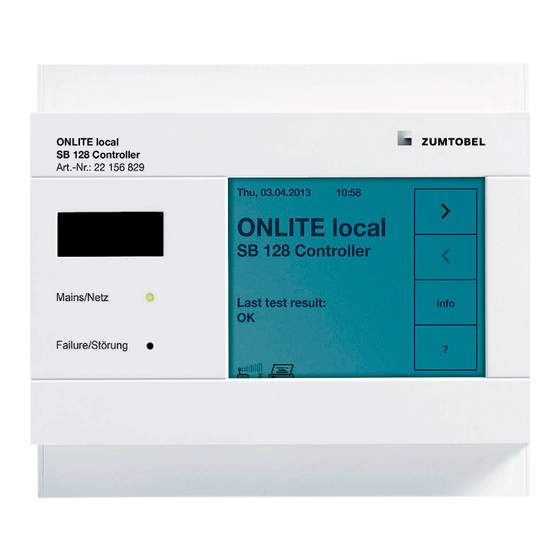
Page 27: Commissioning
• Compare all works performed with the plans and drawings. General notes concerning operation The ONLITE local SB 128 Controller is operated menu-driven via the touch panel located on the front panel. All messages (system, status and error messages) are displayed on the touch panel. -
Page 28: Control Keys On The Touch Panel
Alternatively, the appropriate tab symbol (e.g. ) or the submenu symbol can be clicked. Leads from the quick menu back to the start screen (basic display). The down-arrow leads from the menu selection to the submenus of the tabs. ONLITE local SB 128 Controller... - Page 29 While the basic display is shown, this key opens a window providing information on the ONLITE local SB 128 Controller. Here, you can call the help system. If a submenu is visible, the related help information is called.
- Page 30 One of several options can be selected from the options list. Click on the arrow key to open the options list and select the desired entry by clicking on it. Scroll bars for scrolling the screen. ONLITE local SB 128 Controller...
-
Page 31: Leds On The Device
A failure has occurred during a duration test or a function test. To eliminate a failure, the test has to be performed again with a positive result. LED flashes The ONLITE local SB 128 Controller is blocked, refer to section 6.1 on page 31. ONLITE local SB 128 Controller... -
Page 32: Main Menu
The test logs can then be viewed in the test book. Line 5 displays the symbols of the connected devices: Printer GSM module: The number of bars indicates the signal strength (max. 5 bars). ONLITE local SB 128 Controller... -
Page 33: Quick Menu
DALI bus so that luminaires which had a power failure while locked remain locked (otherwise the emergency lighting electronic ballast would unlock when power is restored). ONLITE local SB 128 Controller... -
Page 34: Start Function Test
Cancel function test Pressing this key terminates the test and the display shows the start screen. Note All other Quick menu commands are inactive while the function test is running. ONLITE local SB 128 Controller... -
Page 35: Start Duration Test
This cycle is repeated again on the following day. If there is still a negative result for the duration test, this result is stored and the status is set. ONLITE local SB 128 Controller... -
Page 36: Test Functions
Print: Sends the currently selected test book entry to the specified printer. The print command does only work, if the ONLITE local SB 128 Controller is connected to a printer. IrDA: Exports the test book entries to reachable IrDA devices (e.g. Laptop, PDA). -
Page 37: Automatic Function Test
(until the set time of day is matching). An error message appears when attempting to start the test manually while the system is blocked. Battery faults can only be eliminated by performing a "duration test". ONLITE local SB 128 Controller... -
Page 38: Automatic Duration Test
It can also be selected whether the duration test of the respective group is to be carried out for luminaires with even numbers and/or for luminaires with odd numbers. ONLITE local SB 128 Controller... - Page 39 • Type of activation: "Manual release": manual test. "Programmed time": automatic test. • Progress of the running duration test (indicated in hours and minutes). Cancel test Press this key to abort the running duration test. ONLITE local SB 128 Controller...
-
Page 40: Inspection Test
, the controller immediately changes the switching status of the selected relay. The buzzer and the failure indication are switched on or off accordingly. Note All relays return to the normal setting when exiting the menu. ONLITE local SB 128 Controller... -
Page 41: Luminaires
Luminaire 1, last from the left is Luminaire 64). The following luminaires status are possible: Switched on. Switched off. Charging error. Defective. Communication error. Not available. Duration test delayed. Test error. Test in progress. ONLITE local SB 128 Controller... -
Page 42: Luminaires Settings
• Pushbutton input S2 acts on group 2 or individual luminaires in group 2. • Pushbutton input S3 acts on group 3 or individual luminaires in group 3. • Pushbutton input S4 acts on group 4 or individual luminaires in group 4. ONLITE local SB 128 Controller... - Page 43 • "Switching mode": Maintained, Non-Maintained or S1 (switched maintained). • "Site text" refers to the "Location" field. • "Lamp text" refers to the "Lamp type" field. • "Information text" refers to the "add. Info" field. ONLITE local SB 128 Controller...
-
Page 44: Luminaires Setup
In case a part of the luminaires could not be found, a message appears asking whether the missing luminaires are to be removed from the list (only in case of emergency luminaires). ONLITE local SB 128 Controller... - Page 45 The ONLITE local SB 128 Controller now searches the selected DALI group for connected luminaires and displays the number of detected new luminaires. The system distinguishes between DALI emergency luminaires and other luminaires. Selection of the assignment method ...
- Page 46 The button changes from auto-search to STOP. • Press STOP as soon as the luminaire you want to assign next lights up brightly. The cyclic lighting is interrupted and the button shows auto-search again. ONLITE local SB 128 Controller...
- Page 47 This way, the luminaires are assigned in the order in which they are detected to the next free logical addresses. Repeat the steps described above for the remaining DALI groups. ONLITE local SB 128 Controller...
- Page 48 ONLITE local SB 128 Controller. This also deletes the DALI address stored in the ballast as well as the information stored in the ONLITE local SB 128 Controller's luminaires list (parameters, info texts). • Replace device: If a luminaire on the bus fails and is replaced by another, all settings of the old luminaire can be transferred to the new one here.
-
Page 49: Setting Up Groups With Onlite Local Extender
• Reinitialization. The system always searches for extenders first. They are found in the next step. After a successful search, none of the luminaires connected to the ONLITE local Extender module are lighting at first. ONLITE local SB 128 Controller... - Page 50 • Resolve double address: Using this item, conflicts caused by double addressing of extender modules can be eliminated. ONLITE local SB 128 Controller...
- Page 51 The setup of the luminaires has to be started directly at the ONLITE local SB 128 Controller. Access via GSM mobile phone is only possible while the assignment dialog is active. All other steps during the setup procedure have to be performed directly at the ONLITE local SB 128 Controller. ONLITE local SB 128 Controller...
-
Page 52: Message Assignments To Relays / Buzzer / Gsm
• Mains operation (no tests are in progress and there are no errors). • Function test or duration test is currently running. • During the last test a lamp fault, battery fault or ballast fault occurred. • Communication problem on the DALI bus. ONLITE local SB 128 Controller... - Page 53 Factory settings: Press this key to reset the message assignments to the factory settings (according to VDE 0801). Note When using a remote display for emergency lighting systems, pay attention to national guidelines and regulations. ONLITE local SB 128 Controller...
-
Page 54: Connected Devices
If configured accordingly, an SMS is sent to the entered number in the event of a failure. Hands-free operation: Allows you to talk to colleagues while installing the system, for example. ONLITE local SB 128 Controller... - Page 55 (e.g. for speaking with the colleague while assigning) or terminated. The ONLITE local SB 128 Controller continuously checks the state of the ONLITE GSM module. If required, the following notes are displayed instead of the setup window shown above.
- Page 56 In order to activate remote control, a PIN code has to be defined. This PIN code has to be entered on the calling mobile phone. Remote maintenance is allowed, if the entered PIN code is correct. ONLITE local SB 128 Controller...
-
Page 57: Printer
• Configuration: Prints the current configuration of the ONLITE local SB 128 Controller. 10.4 IrDA interface The ONLITE local SB 128 Controller is equipped with an IrDA interface. To open the IrDA menu, open the "Connected Devices" menu (refer to section 10.1 on page 52) and click on "IrDA". - Page 58 "Configuration (text)": • All tests: Transmits an overview of the executed tests. • Last function test and Last duration test: Transmits the latest function and duration test results. ONLITE local SB 128 Controller...
-
Page 59: Modbus
10.5 ModBus The ModBus interface allows networking of the ONLITE local SB 128 Controller, e.g. with the GO-ON package. To open the ModBus menu, open the "Connected Devices" menu (refer to section 10.1 on page 52) and press "ModBus". ... -
Page 60: System (Equipment) Configuration
Device-Infotext: Press the text in order to edit the device designation. With the help of the device designation the ONLITE local SB 128 Controller devices can be distinguished. It is visible in the main menu and used within SMS messages. -
Page 61: Display
Changes are immediately visible. 11.4 Service Software Version: Displays the version number of the currently running software. More options: A special password is required to access these options. They are not required during normal operation. ONLITE local SB 128 Controller... - Page 62 ONLITE local SB 128 Controller...
Need help?
Do you have a question about the ONLITE local SB 128 Controller and is the answer not in the manual?
Questions and answers