Advertisement
Quick Links
General Information:
Read through carefully before beginning assembly.
»
When assembling components, place on a clean, flat,
»
non-abrasive surface to avoid scratches.
In the event of missing or defective parts, please call our
»
customer service department directly at 1-877-258-6020
Tools required:
Cordless Drill with #2 phillips bit
»
Hammer
»
Tape Measure
»
Shovel
»
Post Hole Digger (recommended)
»
FIGURE 2
Ground Anchor Layout
for installation
hartford Arbor
Assembly & installation Instructions
Part #
Description
1
4" sq. x 72" Left Post
2
4" sq. x 72" Right Post
3
2" sq. x 36¾" Top/Bottom Cross Rail
4
2" sq. x 36¾" Center Cross Rail
5
⅞ x 1½ x 59½" Outside Vertical Rail
6
⅞ x 1½ x 59½" Middle Vertical Rail
7
⅞" x 1½" x 16" Rail
8
4" sq. Arbor Top Arch Half
9
3¾" x 6" Arbor Top Connector Tube (2)
10
Decorative Knuckle
11
2" sq. x 36¾" Rail
12
24" U-channel Ground Anchor
13
Hardware Kit (includes):
1½" Kappet Screws
¾" Kappet Screws
Kappet Screw Caps
1" Self-tapping White-head Screws
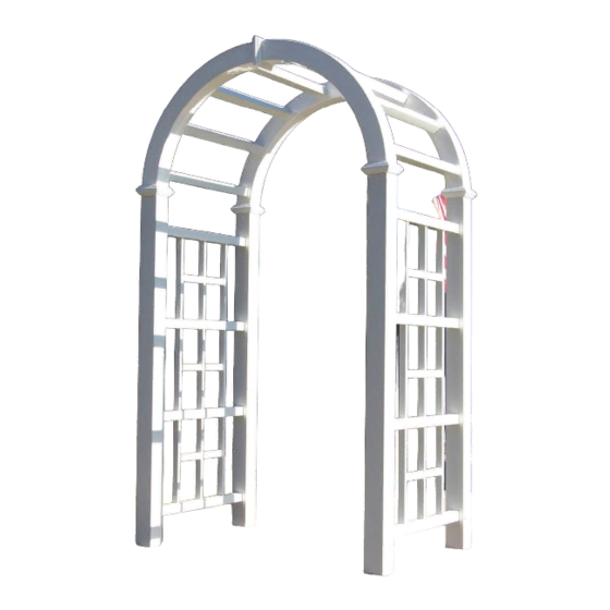
FIGURE 1
Product dimensions &
Part identification
Parts List:
(Box Number)
(1)
(2)
(1)
(1)
(1 & 2)
(2)
(2)
(2)
(2)
Qty
2
2
4
(1)
4
4
(1)
2
(1)
6
4
6
6
8
4
20
36
56
8
Advertisement

Subscribe to Our Youtube Channel
Related Manuals for Dura Trel Hartford Arbor


Summary of Contents for Dura Trel Hartford Arbor
- Page 1 Arbor Assembly & installation Instructions Parts List: Part # Description (Box Number) 4” sq. x 72” Left Post 4” sq. x 72” Right Post 2” sq. x 36¾” Top/Bottom Cross Rail 2” sq. x 36¾” Center Cross Rail ⅞ x 1½ x 59½” Outside Vertical Rail ⅞...
- Page 2 Lay out one outside vertical rail (part 5). Insert one 16” rail (part 7) into center hole. Insert free end of 16” rail through center hole of one middle vertical rail (part 6). Insert free end of the 16” rail into center hole of another outside vertical rail (part 5).
- Page 3 Insert free ends of vertical rails into corresponding holes of each top/ bottom cross rail (part 3). Lay out one right post (part 2). Insert cross rails of assembly into corresponding holes of right post. Slide left post (part 1) onto corresponding holes of assembly.
- Page 4 Lay out one arbor top arch half (part 8). Insert four 36¾” rails (part 11) into arch half. Slide another arch half over 36¾” rails. Using 1½” kappet screws, screw together arbor top half. Be sure that all parts are fully inserted before securing.
- Page 5 Slide one decorative knuckle (part 10) over each connector tube and arch half. Slide the knuckle up to the screws fastened in step 10. Connect two arbor halves by inserting connector tubes into ends of remain- ing arbor half. Insert into ends where arbor half was fastened together in step 8.
- Page 6 Insert one arbor top connector tube (part 9) into end of each post with three pilot holes. Connector tube will insert half way, resting on cross rail (at black mark). Using ¾” kappet screws, fasten connector tubes to posts. Snap kappet screw caps over screw heads.
-
Page 7: Arbor Installation
ARBOR INSTALLATION Option 1 Slide one 24” steel u-channel ground anchor (part 12) into bottom of each post. Slide ground anchor until it meets bottom cross rail. Using 1” self- tapping white-head screw fasten post to ground anchor. Using ground anchor installation layout drawing (figure 2), dig holes approximately 16”...
Need help?
Do you have a question about the Hartford Arbor and is the answer not in the manual?
Questions and answers