Table of Contents
Advertisement
SERVICE GELATO DISPLAY CASE - LOW TEMPERATURE UNITS
> NOTE: DIPWELL COMPONENTS VARY DEPENDING UPON MODELS AND OPTIONS CHOSEN.
I:\Oper Manual\Encore\G12F_G12F-4759_G18F_G24F_99739.pub
READ AND SAVE THESE INSTRUCTIONS
INSTALLATION AND
OPERATING MANUAL
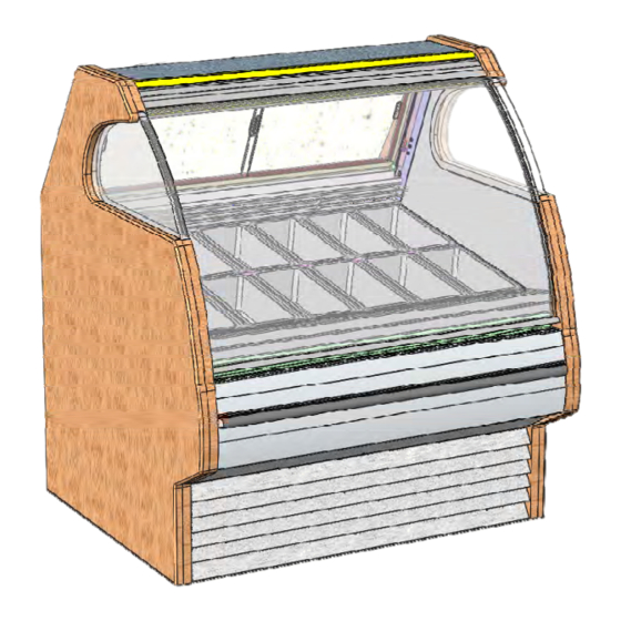
Model G12F.5150F
Is Shown At Right.
Your Model May Differ.
Model G12F / G12F.4759 / G12F.5150...47 1/2"L* x 43 3/8"D x 53 3/4"H**
Model G18F / G18F.4888A..................67 1/2"L* x 43 3/8"D x 53 3/4"H**
Model G24F......................................84 1/2"L* x 43 3/8"D x 53 3/4"H**
*Includes 2" End Panels
**Includes Levelers at 1 1/4" Below Base Frame
888 E. Porter Road · Muskegon, MI 49441 Phone: 231.798.8888 Fax: 231.798.4960 www.structuralconcepts.com
PN 99739
Model G24F
Is Shown At Left.
Your Model May Differ.
Rev R Date: 7.27.2016
Advertisement
Table of Contents
Troubleshooting

Subscribe to Our Youtube Channel
Related Manuals for Structural Concepts ENCORE Series


Summary of Contents for Structural Concepts ENCORE Series
- Page 1 READ AND SAVE THESE INSTRUCTIONS INSTALLATION AND PN 99739 OPERATING MANUAL SERVICE GELATO DISPLAY CASE - LOW TEMPERATURE UNITS > NOTE: DIPWELL COMPONENTS VARY DEPENDING UPON MODELS AND OPTIONS CHOSEN. Model G24F Is Shown At Left. Your Model May Differ. Model G12F.5150F Is Shown At Right.
-
Page 2: Table Of Contents
TABLE OF CONTENTS OVERVIEW / TYPE / COMPLIANCE / WARNINGS / PRECAUTIONS / WIRING / PLUGS …………... INSTALLATION …………………………………………………………………………………….……..……. START-UP / OPERATING / MAINTENANCE / DRAIN SYSTEMS SECTION ………………………….. START-UP AND OPERATION .…………...…...…..……………………………………..……….……..…… MAINTENANCE FUNDAMENTALS ……………………………...………………………….…………..…… MODEL G12F DRAIN SYSTEM (Self-Contained Units With Optional Evaporator Pan Only) ………..MODEL G12F.5150 DIPWELL™DRAIN SYSTEM (Note: Dipwell™Configuration May Not Be Applicable To Your Case) ……………………………………………………………………………... -
Page 3: Overview / Type / Compliance / Warnings / Precautions / Wiring / Plugs - Page 1 Of 2
OVERVIEW For Type 2 Conditions: ambient conditions are to be at 60% maximum humidity and maximum temperatures The Structural Concepts® Glass Front, Freezer of 80 °F [27 °C]. Service Gelato Display Case is designed to If unsure if unit is designed for Type 1 or 2, see tag merchandise gelato and/or soft ice cream into cones, next to serial label. - Page 4 OVERVIEW / TYPE / COMPLIANCE / WARNINGS / PRECAUTIONS / WIRING / PLUGS - PAGE 2 of 2 PRECAUTIONS WIRING DIAGRAM This sheet contains important precautions to prevent Each case has its own wiring diagram folded and in damage to unit or merchandise.
-
Page 5: Installation
INSTALLATION Installation: Units shown may not depict an exact representation of your particular unit being installed. Block Slide 2. Case Aligning, Adjusting and Sealing Support Skid required For Service Glass to align properly, case must be to prevent level and plumb. Adjust feet accordingly (see tipping. -
Page 6: Start-Up / Operating / Maintenance / Drain Systems Section
START-UP / OPERATING / MAINTENANCE / DRAIN SYSTEMS SECTION START-UP / OPERATING / MAINTENANCE / DRAIN SYSTEMS... -
Page 7: Start-Up And Operation
START-UP AND OPERATION Merchandiser Start-Up Self-Contained: Main Power switch is located at case rear, lower left. See illustration at lower right and lower left. Remote Units: Case is hard-wired. When power is supplied, case will power-up. Lights: Turn on the lights. Whether Remote or Self-Contained, light switch is located on inside of case at top left, from case rear. -
Page 8: Maintenance Fundamentals
MAINTENANCE FUNDAMENTALS Light Fixtures Warning! Disconnect power before providing maintenance and service to unit. Caution: Lamps have been treated to resist breakage and must be replaced with similarly treated lamps. Light fixtures are to be located on underside of shelf assembly, at the top inside of case, and lower front nose of case. -
Page 9: Model G12F Drain System (Self-Contained Units With Optional Evaporator Pan Only)
MODEL G12F DRAIN SYSTEM (Standard Self-Contained Units With Optional Evaporator Pan Only) Self-Contained Units have Drain Systems that allow thorough defrost and interior cleaning. Default Drain Valve setup (from manufacturer) is with Internal Evaporator Pan being utilized. Model G12F View of Case Rear (Your Model May Vary) External Drain... -
Page 10: Applicable To Your Case)
MODEL G12F.5150 DRAIN SYSTEM (Dipwell™ Configuration May Not Be Applicable To Your Case) This unit is self-contained and is designed to allow thorough defrost and interior cleaning. Default system of this unit (from manufacturer) is WITHOUT internal evaporator pan. ... -
Page 11: Model G18F Drain System (Self-Contained Units With Optional Evaporator Pan Only)
MODEL G18F DRAIN SYSTEM (Self-Contained Units With Optional Evaporator Pan Only) Self-contained units have drain systems that allow thorough defrost and interior cleaning. > Default drain valve setup (from manufacturer) is with internal evaporator pan being utilized. External Drain Note : Model and options chosen may affect location of valves, drains, controller, Drain... -
Page 12: Model G24F Drain System (Self-Contained Units With Optional Evaporator Pan Only)
MODEL G24F DRAIN SYSTEM (Self-Contained Units With Optional Evaporator Pan Only) Self-Contained Units have Drain Systems that allow thorough defrost and interior cleaning. Default Drain Valve setup (from manufacturer) is with Internal Evaporator Pan being utilized. External Drain Note : Model and options chosen may affect location of valves, drains, controller, Drain... -
Page 13: Store Employees' Section Only
STORE EMPLOYEES’ SECTION ONLY ILLUSTRATIONS, INSTRUCTIONS AND INFORMATION CONTAINED IN THIS SECTION PERTAINS TO STORE EMPLOYEES ONLY... -
Page 14: Cleaning Schedule (To Be Performed By Store Personnel)
CLEANING SCHEDULE (TO BE PERFORMED BY STORE PERSONNEL) / “D” = DAILY / “W” = WEEKLY Cleaning Task Area Glass: Clean side glass, front curved glass and sliding glass rear doors (optional) Clean Case with a household or commercial glass cleaner. Exterior Dipwell™... -
Page 15: Weekly Cleaning (To Be Performed By Store Personnel) - Page 1 Of 4
WEEKLY CLEANING (TO BE PERFORMED BY STORE PERSONNEL) - PAGE 1 of 4 CAUTION! YOU MUST PERFORM THIS CLEANING PROCEDURE EVERY 7 DAYS TO PREVENT ICE BUILDUP AND TO KEEP CASE RUNNING AT PROPER TEMPERATURE. Note: Full defrost process takes at least 6 hours (and is often performed overnight). ... - Page 16 WEEKLY CLEANING (TO BE PERFORMED BY STORE PERSONNEL) - PAGE 2 of 4 CAUTION! YOU MUST PERFORM THIS CLEANING PROCEDURE EVERY 7 DAYS TO PREVENT ICE BUILDUP AND TO KEEP CASE RUNNING AT PROPER TEMPERATURE. Cleaning Instructions Continued… 11. Remove knurled head fasteners (at rear of unit). See illustration #11 below.
- Page 17 WEEKLY CLEANING (TO BE PERFORMED BY STORE PERSONNEL) - PAGE 3 of 4 CAUTION! YOU MUST PERFORM THIS CLEANING PROCEDURE EVERY 7 DAYS TO PREVENT ICE BUILDUP AND TO KEEP CASE RUNNING AT PROPER TEMPERATURE. Cleaning Instructions Continued… 16. Lift fan shroud assembly up and out. 17.
- Page 18 WEEKLY CLEANING (TO BE PERFORMED BY STORE PERSONNEL) - PAGE 4 of 4 CAUTION! YOU MUST PERFORM THIS CLEANING PROCEDURE EVERY 7 DAYS TO PREVENT ICE BUILDUP AND TO KEEP CASE RUNNING AT PROPER TEMPERATURE. Cleaning Instructions Continued… 28. Place support rails across case (slots are at both front and rear of case).
-
Page 19: Troubleshooting (To Be Performed By Store Personnel)
TROUBLESHOOTING (TO BE PERFORMED BY STORE PERSONNEL) Doors/Glass Won’t Shut Properly Check that there is no residue or obstruction in door track. System Is Not Operating Check the MAIN power switch is on. If power cord is used, check that it is properly plugged in. Case Lights Are Not Working Be sure ALL light bulb pins are properly aligned with slots and rotated properly. -
Page 20: Trained Service Providers Section Only
TRAINED SERVICE PROVIDERS SECTION ONLY ILLUSTRATIONS, INSTRUCTIONS AND INFORMATION CONTAINED IN THIS SECTION PERTAINS TO TRAINED SERVICE PROVIDERS ONLY... -
Page 21: Preventive Maintenance (To Be Performed By Trained Service Providers Only)
PREVENTIVE MAINTENANCE (TO BE PERFORMED BY TRAINED SERVICE PROVIDERS) PREVENTIVE FREQUENCY INSTRUCTIONS MAINTENANCE Case Exterior Monthly Condensing Coil: Disconnect power from case before cleaning. Remove rear grille (by removing 4 screws). Slide/roll out refrigeration assembly. Note: At initial slide-out, it may be necessary to remove two (2) compressor pan shipment screws for refrigeration assembly to slide out. - Page 22 PREVENTIVE MAINTENANCE (TO BE PERFORMED BY TRAINED SERVICE PROVIDERS), CONT’D PREVENTIVE FREQ. INSTRUCTIONS MAINTENANCE Case Interior Quarterly Internal Cleaning: Disconnect power from case before cleaning. 1. Remove pans and support rails. 2. Remove fan cover panels (after removing knurled head fasteners). 3.
- Page 23 PREVENTIVE MAINTENANCE (TO BE PERFORMED BY TRAINED SERVICE PROVIDERS), CONT’D PREVENTIVE FREQ. INSTRUCTIONS MAINTENANCE Condensate Pan Quarterly Condensate Pan: Disconnect power from case and allow pan to cool before cleaning. Remove rear panel (screw removal is required). As illustration below shows, pan may be accessed at either left or right sides. ...
- Page 24 PREVENTIVE MAINTENANCE (TO BE PERFORMED BY TRAINED SERVICE PROVIDERS), CONT’D PREVENTIVE FREQ. INSTRUCTIONS MAINTENANCE Condensate Quarterly Condensate Package Disconnect power from case before cleaning. Package Remove rear panel (screw removal is required). Slide condenser package out from under case rear. ...
-
Page 25: Troubleshooting (To Be Performed By Trained Service Providers Only)
TROUBLESHOOTING (TO BE PERFORMED BY TRAINED SERVICE PROVIDERS) Doors/Glass Won’t Shut Properly Check that there is no residue or obstruction in door track. Check that the case is aligned, level and plumb. System Is Not Operating If power cord is used, check that it is properly plugged in. Check the MAIN power switch is on. -
Page 26: General Technical Information
GENERAL TECHNICAL INFORMATION (SERIAL LABEL INFO / TEMPERATURE CONTROLLER, ETC.) GENERAL TECHNICAL INFORMATION (SERIAL LABEL INFO / TEMPERATURE CONTROLLER INFORMATION / TECHNICAL SERVICE INFORMATION), ETC. -
Page 27: Serial Label Location & Information Listed / Tech Info & Service
For additional technical information and service, see the TECHNICAL SERVICE page in this manual for instructions on contacting Structural Concepts’ Technical Service Department. See images below for samples of both refrigerated and non-refrigerated serial labels. -
Page 28: Carel® Temperature Controller
Read And Save These Instructions - Page 1 of 3 Integrated Electronic Microprocessor Controller Programming The Instrument ▲ mute To Modify The Setpoint ▼ Press and hold the “SET” key for at least 1 second. 2. Use arrow keys ▲ ▼ on temperature ▲... - Page 29 Read And Save These Instructions - Page 2 of 3 Integrated Electronic Microprocessor Controller User Interface - Display Summary Table of Alarm and Signals: Display, Buzzer and Relay reset alarms w/manual reset / reset HACCP alarms / reset temp. monitoring...
- Page 30 Read And Save These Instructions - Page 3 of 3 Integrated Electronic Microprocessor Controller Summary Table of Operating Parameters CODE PARAMETER UOM* TYPE MINIMUM MAXIMUM DEFAULT Select Celsius (°C) or Fahrenheit (°F) flag Calibration of probe 1 °C/°F Calibration of probe 2 °C/°F For Case Specific...
-
Page 31: Technical Service Contact Information & Warranty Information
LIMITED WARRANTY All sales by Structural Concepts Corporation (SCC) are subject to the following limited warranty. “Goods” refers to the product or products being sold by SCC. Warranty Scope: Warranty is for equipment sold in the United States, Canada, Mexico and Puerto Rico. Equipment sold elsewhere may carry modified warranty.
Need help?
Do you have a question about the ENCORE Series and is the answer not in the manual?
Questions and answers