Table of Contents
Advertisement
READ AND SAVE THESE INSTRUCTIONS
SCC P/N
INSTALLATION AND
OPERATING MANUAL
54221
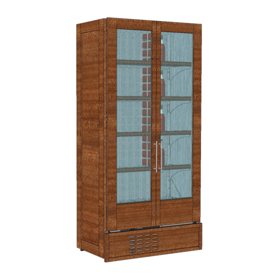
REFRIGERATED WINE AND DRY LIQUOR MERCHANDISERS
Model W3R / CDR4287
(Refrigerated Wine Units)
Model W4R
(Refrigerated Wine Unit)
Model CDR4287A
(Stand-Alone
Refrigerated Wine Unit)
Refrigerated Wine Units: Model CDR4287A
(Left) Adjoined To Model B428WN (Right)
Model B427WND (Refrigerated Wine
Unit w/Self-Closing Locking Doors)
Model B427WNDD (Dry Liquor
Unit w/Self-Closing Locking Doors)
Model B427WN
(Refrigerated Wine Unit)
888 E. Porter Rd ∙ Muskegon, MI 49441 Ph: 231.798.8888 Fax: 231.798.4960 www.structuralconcepts.com
Oper Manuals\Oasis\W3R_W4R_CDR4287_CDR4287A_B427WN_B428WND_B427WNDD_B428WN_54221.pub
Rev I Date: 8.26.2019
Advertisement
Table of Contents
Troubleshooting

Subscribe to Our Youtube Channel
Related Manuals for Structural Concepts Oasis W3R


Summary of Contents for Structural Concepts Oasis W3R
- Page 1 READ AND SAVE THESE INSTRUCTIONS SCC P/N INSTALLATION AND OPERATING MANUAL 54221 REFRIGERATED WINE AND DRY LIQUOR MERCHANDISERS Model W3R / CDR4287 (Refrigerated Wine Units) Model W4R (Refrigerated Wine Unit) Model CDR4287A (Stand-Alone Refrigerated Wine Unit) Refrigerated Wine Units: Model CDR4287A (Left) Adjoined To Model B428WN (Right) Model B427WND (Refrigerated Wine Unit w/Self-Closing Locking Doors)
-
Page 2: Table Of Contents
TABLE OF CONTENTS OVERVIEW / NSF® TYPE / COMPLIANCE / WARNINGS / PRECAUTIONS / WIRING………………. INSTALLATION …………………………………………………………………………………………..…….. LOWER FRONT PANEL GRILLE REMOVAL (WITH HOOKS & SLOTS) ………………………….….. LOWER LOUVERED FRONT PANEL REMOVAL (SCREW REMOVAL) ……………………………..CASE START-UP: ACCESS TO TEMP. CONTROLLER / MAIN POWER / REFRIGERATION PACKAGE SLIDE-OUT ………………………………….……...………………..…………….…... -
Page 3: Overview / Nsf® Type / Compliance / Warnings / Precautions / Wiring - Page 1 Of 2
OVERVIEW If unsure if unit is NSF® Type 1 or 2, see tag near serial label. These Structural Concepts merchandisers are designed to COMPLIANCE merchandise packaged products at 41 °F (5 °C) or less product temperatures (unless custom cases with wire rack Performance issues when in violation of applicable NEC, shelving). - Page 4 OVERVIEW / NSF® TYPE / COMPLIANCE / WARNINGS / PRECAUTIONS / WIRING - PAGE 2 of 2 PRECAUTIONS WIRING DIAGRAM This sheet contains important precautions to prevent Each case has its own wiring diagram folded and in damage to unit or merchandise. its own packet.
-
Page 5: Installation
INSTALLATION 1. Removing Case Shipping Brackets That Are Attached To Skid Remove screws holding Case Shipping Brackets to skid. Remove Case Shipping Brackets from Skid. See illustrations below. Note: Shipping Brackets will vary in size, shape, material and location depending upon case type and model. -
Page 6: Lower Front Panel Grille Removal (With Hooks & Slots) - Page 1 Of 2
LOWER FRONT PANEL GRILLE REMOVAL (WITH HOOKS & SLOTS) - PAGE 1 of 2 1. Removing Lower Front Panel Grille From Case - With Hooks & Slots Grasp lower front panel wood grille (attached to metal front panel) and carefully lift upward. ... -
Page 7: Lower Louvered Front Panel Removal (Screw Removal) - Page 2 Of 2
LOWER LOUVERED FRONT PANEL REMOVAL (SCREW REMOVAL) - PAGE 2 of 2 2. Removing Lower Louvered Front Panel From Case - Screw Removal Method Remove two (2) screws holding lower louvered front panel to case. See illustration below. Grasp front panel slats and lift upward and away from case. -
Page 8: Package Slide-Out
CASE START-UP: ACCESS TO TEMP. CONTROLLER / MAIN POWER / REFRIG. PKG. SLIDE-OUT 2. Main Power (And LED Lights) 1. Access To Temperature Controller After lower louvered front panel has been Turn on Main Power Switch for Power and LED lights to come on. -
Page 9: Case Start-Up: Honeycomb Air Diffuser Discharge
CASE START-UP, CONTINUED: HONEYCOMB AIR DIFFUSER 4. Honeycomb Air Diffuser When main power switch is turned on, refrigeration assembly will energize. Evaporator coil fans should turn on. From inside-upper section of case, check for discharge air from honeycomb air diffuser (shown at right) to confirm that the fans are functioning properly. -
Page 10: Condensate Pan Access (From Case Rear)
CONDENSATE PAN ACCESS (FROM CASE REAR) Accessing Condensate Pan From Case Rear Note: Depending upon model, refrigeration package may also be accessible from case front. Sliding refrigeration package out should allow access to condensate pan. However, should greater access be desired, rear panel can be removed. -
Page 11: Fan & Coils
TXV VALVE & COVER / DRAIN & DRAIN ACCESS COVER / “P-TRAP” / EVAPORATOR FAN & COILS Evaporator Coil / TXV Valve / Drain / “P-Trap,” etc. Cover, Drain & Drain Access Cover, “P-Trap”, Evaporator Fan & Coils. Illustrations below reflects several models’ layouts ... -
Page 12: Operation
LED LIGHT FIXTURES: ROCKER SWITCH / LED LIGHT ‘TOUCH SENSOR’ LOCATION & OPERATION 1. LED Lights On & Off / Dimming Feature / Location LED lights are controlled by either an On/Off rocker switch or a “touch sensor” with dimming capabilities. See illustration on this page for views of each. -
Page 13: Led Light Fixtures: Removal And Replacement
(Typ.) LED Light (Typ.) 1. LED Style Light Fixtures Removal of Faulty LED Lights: Contact Structural Concepts’ Technical Service Department for replacement LED lights. Turn off LED light switch. To remove faulty LED light, follow these steps: A. -
Page 14: Led Light Fixtures, Cont'd: 'Plug-In' Instructions
LED LIGHT FIXTURES, CONT’D: ‘PLUG-IN’ INSTRUCTIONS >> Note: Mounting clips MAY be riveted to shelf or header. In such instances, simply remove LED light from mounting clips by pressing against flange part of clips with thumb. Replacement of LED lights: ... -
Page 15: Cdr4287A And B427Wnd
CONDENSATE PAN ACCESS / REFRIG. PKG. LAYOUT FOR CDR4287, A & B427WND - PAGE 1 OF 3 1. Condensate Pan Access (Models CDR4287, Remove the (4) screws holding condensate pan feet to condensate pan support. CDR4287A and B427WND) Carefully slide the condensate pan off from the Warning! Disconnect power before providing condensate pan support. -
Page 16: Refrigeration Package Layout For Model B428Wn
REFRIGERATION PACKAGE LAYOUT FOR MODEL B428WN - PAGE 2 OF 3 2. Refrigeration Package Layout For Model B428WN Warning! Disconnect power before providing maintenance and service to unit. See CONDENSATE PAN ACCESS / REFRIG. PACKAGE LAYOUT (CDR4287 / A / B427WND) - PAGE 1 OF 3 section in this manual for instructions on front grille removal, condensate pan access, etc. -
Page 17: Refrigeration Package Layout & Access For Model B427Wn - Page 3 Of 3
REFRIGERATION PACKAGE LAYOUT & ACCESS FOR MODEL B427WN - PAGE 3 OF 3 3. Refrigeration Package Layout For Model B427WN Warning! Disconnect power before providing maintenance and service to unit. See CONDENSATE PAN ACCESS / REFRIG. PACKAGE LAYOUT (CDR4287 / A / B427WND) - PAGE 1 OF 3 section in this manual for instructions on front grille removal, condensate pan access, etc. -
Page 18: Cleaning Schedule - To Be Performed By Store Personnel
CLEANING SCHEDULE - TO BE PERFORMED BY STORE PERSONNEL AREA TO BE FREQUENCY INSTRUCTIONS CLEANED Case Exterior Daily Front / Sides of Case (Including Wood Surfaces): Clean with a warm water and mild soap solution and soft cloth (damp, not soaked). Be sure to dry surfaces after wiping with damp, soft cloth. -
Page 19: Preventive Maintenance (Performed By Trained Service Provider)
PREVENTIVE MAINTENANCE (TO BE PERFORMED BY TRAINED SERVICE PROVIDER) - Page 1 of 2 WARNING! TURN OFF CASE BEFORE PERFORMING PREVENTIVE MAINTENANCE! PREVENTIVE FREQ. INSTRUCTIONS MAINTENANCE Case Exterior Quarterly Under Case Cleaning: When refrigeration package is removed from underside of case, vacuum under case to remove all dust, debris and dirt that collects. Quarterly Condensate Pan: ... - Page 20 PREVENTIVE MAINTENANCE (TO BE PERFORMED BY TRAINED SERVICE PROVIDER) - Page 2 of 2 Honeycomb Air Diffuser Removal Clean honeycomb with warm water and soap solution. Submerse if necessary. Use brush to See PREVENTIVE MAINTENANCE (TO BE dislodge stubborn or sticky residue. Dry by using PERFORMED BY TRAINED SERVICE PROVIDER) vacuum’s blow mode (vs.
-
Page 21: Troubleshooting - General Issues
TROUBLESHOOTING - GENERAL ISSUES CONDITION TROUBLESHOOTING Water Is On The Floor Check that the drain trap is free of debris. Check that the drain hose is correctly positioned over condensate pan (or floor drain, for remote units). Check store conditions. Conditions should be 55% humidity and at a temperature of 24 °C / 75 °F to prevent condensation. - Page 22 TROUBLESHOOTING - GENERAL ISSUES, CONTINUED CONDITION TROUBLESHOOTING Case Lights Are Not Working, Check for burned out LED lights. Contact Structural Concepts continued Corporation for replacement. See Technical Service section in this manual for contact information. Check to insure voltage at ballasts. If voltage is entering but not exiting ballast, ballast is faulty.
-
Page 23: Troubleshooting - Condensing System
TROUBLESHOOTING - CONDENSING SYSTEM (BY TRAINED SERVICE PROVIDERS ONLY) CONDITION TROUBLESHOOTING Head Pressure Too High Check that the condensing coil is not dirty or covered. Check that condensing fans are working. Check that refrigerant is not overcharged. Perform sub-cooling check and verify that no contaminates are in system. Check that liquid line filter dryer is not plugged. -
Page 24: Troubleshooting - Evaporator System
TROUBLESHOOTING - EVAPORATOR SYSTEM (BY TRAINED SERVICE PROVIDERS ONLY) CONDITION TROUBLESHOOTING Low Suction Pressure Check if sight glass is flashing or showing low charge. Check that expansion valve (TXV) isn’t restricted. Check element charge. Check that liquid line or filter isn’t restricted. Check that refrigeration lines and/or hoses are not kinked on either high or low sides. -
Page 25: Serial Label Information & Location
For additional technical information and service, see the TECHNICAL SERVICE page in this manual for instructions on contacting Structural Concepts’ Technical Service Department. See images below for samples of both refrigerated and non-refrigerated serial labels. ... -
Page 26: Carel® Controller - Programming The Instrument
Read And Save These Instructions - Page 1 of 3 Integrated Electronic Microprocessor Controller Programming The Instrument ▲ mute To Modify The Setpoint 1. Press and hold the “SET” key for at least 1 second. ▼ 2. Use arrow keys ▲ ▼ on temperature ▲... -
Page 27: Carel® Controller - User Interface, Summary Tables Of Alarms & Signals
Read And Save These Instructions - Page 2 of 3 Integrated Electronic Microprocessor Controller User Interface - Display Summary Table of Alarm and Signals: Display, Buzzer and Relay reset alarms w/manual reset / reset HACCP alarms / reset temp. monitoring... -
Page 28: Carel® Controller - Summary Table Of Operating Parameters (After Programming Key)
Read And Save These Instructions - Page 3 of 3 Integrated Electronic Microprocessor Controller Summary Table of Operating Parameters CODE PARAMETER UOM* TYPE MINIMUM MAXIMUM DEFAULT flag Select Celsius (°C) or Fahrenheit (°F) Calibration of probe 1 °C/°F Calibration of probe 2 °C/°F For Case Specific... -
Page 29: Technical Service Contact Information & Warranty Information
DAMAGE, STORE’S AMBIENT CONDITIONS, ETC.) LIMITED WARRANTY Overview: All sales by Structural Concepts Corporation (hereafter referred to as “SCC”) are subject to the following limited warranty. “Goods” refers to the product or products being sold by SCC. Warranty Scope: Warranty is for equipment sold in the United States, Canada, Mexico and Puerto Rico. Equipment sold elsewhere may carry modified warranties.
Need help?
Do you have a question about the Oasis W3R and is the answer not in the manual?
Questions and answers