Table of Contents
Advertisement
Quick Links
Advertisement
Table of Contents

Related Manuals for Strobel VEB100-1


Summary of Contents for Strobel VEB100-1
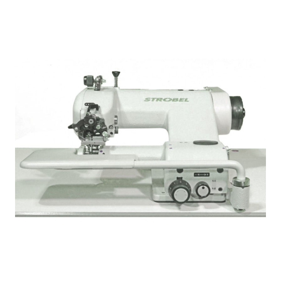
- Page 1 For the professional user Mechanic‘s Instructions Für den professionellen Anwender Mechanikeranleitung Class: VEB100-1 Ausf. 3 Klasse: VEB100-2 Ausf. 3 VEB100-2W Ausf. 3 Model: VEB100-4 Ausf. 1 Ausführung: VEB100-5 Ausf. 1 Dated: Stand: S p e z i a l m a s c h i n e n G m b H...
- Page 2 The sign of quality ou find the Strobel trademark on every Strobel machine leaving our works. And with good reason. This symbol is a guarantee of the high quality of our products. Quality which creates trust – trust in our technology, our service and, not least of all, in our good name.
- Page 3 We wish you lots of success in your work with your new Strobel machine. S p e z i a l m a s c h i n e n G m b H...
-
Page 5: Table Of Contents
2.4.4 Class VEB100-4 ....................14 2.4.5 Class VEB100-5 ....................16 Brief setting instruction....................18 2.5.1 Class VEB100-1, -2, -2W ..................18 2.5.2 Class VEB100-4 ....................19 2.5.3 Class VEB100-5 ....................20 Notes on repair and adjustments ..................... 21 Stitch plate assembly ...................... 21 3.1.1... - Page 6 Presser ..........................35 3.7.1 Replacing the presser shaft (Fig. 12) ..............35 3.7.2 Adjusting the presser (Fig. 13) ................36 3.7.3 Adjusting the material support arm ..............37 3.7.4 Setting the pre-tension of the spring in spring-loaded plungers ..... 38 Pneumatic lifting ......................
- Page 7 259.10.37 Pneumatic construction circuit diagram cl. gen. with pneum. Lifting 259.00.65 Pneumatic circuit diagram cl. VEB100-1, -2, -2W, VEB200-1, -2 with seam lock 259.10.65 Pneumatic construction circuit diagram cl. VEB100-1, -2, -2W, VEB200-1, -2 with seam lock Strobel-Switchable functions (DC1200-AB611A)
- Page 8 MA_VEB100-1-2-2W-4-5_A3-1_190627_en.doc...
-
Page 9: General Notes On Safety
General notes on safety Manuals and additional information can be found on the STROBEL website at: http://www.strobel.biz Every person in charge of setting up, operating, servicing and repairing the machine must first read and understand the operating instructions and particularly the safety instructions before starting up the machine. - Page 10 It is essential that you observe and follow these instructions as well as the generally valid safety regulations. Warning instructions given in the operating instructions that pertain to especially dangerous parts of the machine must be indicated at these positions using a safety symbol.
-
Page 11: General Notes
Range of application and intended use Class VEB100-1 are mainly suitable for blind stitching thin woven and knitted fabrics. Class VEB100-2 are universal hemming machines for thin and medium weight material with cross seams. -
Page 12: Technical Data Of Machines
Technical data of machines 2.4.1 Class VEB100-1 Empfohlene Nennstichzahl / 1800 min-1 Recommended rated speed Stichlänge / stitch length 5,0 - 8,0 mm (abhängig vom Nähmaterial / depend on fabric) Auslieferzustand / delivery condition 8,0 mm Obertransport / top feed Pyramidenverzahnung / pyramid thoothing Sägeverzahnung / saw thoothing optional... - Page 13 Technischer Auslieferzustand / delivery condition Riemenscheibendurchmesser Maschine/ dw 80 mm machine pulley diameter Motor-Leistung min. / min. motor power 550 W Keilriemen-Profil / V-belt profile 10 x 6 mm Zahnriemenscheibe Maschine / Z = 38 toothed belt pulley/machine Zahnriemenprofil / toothed belt profile HTD 5M-9 Stichart / stitch type Einfaden-Kettenstich-Blindstich Typ 103 /...
-
Page 14: Class Veb100-2
2.4.2 Class VEB100-2 Empfohlene Nennstichzahl / 2200 min-1 Recommended rated speed Stichlänge / stitch length 5,0 - 8,0 mm (abhängig vom Nähmaterial / depend on fabric) Auslieferzustand / delivery condition 8,0 mm Obertransport / top feed Pyramidenverzahnung / pyramid thoothing Sägeverzahnung / saw thoothing optional gefederter Drücker / spring loaded plunger Drückervariation optional /... - Page 15 Technischer Auslieferzustand / delivery condition: Riemenscheibendurchmesser Maschine/ dw 80 mm machine pulley diameter Motor-Leistung min. / min. motor power 550 W Keilriemen-Profil / V-belt profile 10 x 6 mm Zahnriemenscheibe Maschine / Z = 38 toothed belt pulley/machine Zahnriemenprofil / toothed belt profile HTD 5M-9 Stichart / stitch type Einfaden-Kettenstich-Blindstich Typ 103 /...
-
Page 16: Class Veb100-2W
2.4.3 Class VEB100-2W Empfohlene Nennstichzahl / 2200 min-1 Recommended rated speed Stichlänge / stitch length 5,0 - 8,0 mm (abhängig vom Nähmaterial / depend on fabric) Auslieferzustand / delivery condition 8,0 mm Obertransport / top feed Pyramidenverzahnung / pyramid thoothing Sägeverzahnung / saw thoothing optional gefederter Drücker / spring loaded plunger Drückervariation optional /... - Page 17 Technischer Auslieferzustand / delivery condition: Riemenscheibendurchmesser Maschine/ dw 80 mm machine pulley diameter Motor-Leistung min. / min. motor power 550 W Keilriemen-Profil / V-belt profile 10 x 6 mm Zahnriemenscheibe Maschine / Z = 38 toothed belt pulley/machine Zahnriemenprofil / toothed belt profile HTD 5M-9 Stichart / stitch type Einfaden-Kettenstich-Blindstich Typ 103 /...
-
Page 18: Class Veb100-4
2.4.4 Class VEB100-4 Empfohlene Nennstichzahl / 1800 min-1 Recommended rated speed Stichlänge / stitch length 2,0 - 5,0 mm (abhängig vom Nähmaterial / depend on fabric) Auslieferzustand / delivery condition 3,0 mm Obertransport / top feed Sägeverzahnung / saw thoothing optional starrer Drücker / fixed plunger Stichplattenöffnung / needle plate opening 4,5 mm... - Page 19 Technischer Auslieferzustand / delivery condition: Riemenscheibendurchmesser Maschine/ dw 80 mm machine pulley diameter Motor-Leistung min. / min. motor power 550 W Keilriemen-Profil / V-belt profile 10 x 6 mm Zahnriemenscheibe Maschine / Z = 38 toothed belt pulley/machine Zahnriemenprofil / toothed belt profile HTD 5M-9 Stichart / stitch type Einfaden-Kettenstich-Blindstich Typ 103 /...
-
Page 20: Class Veb100-5
2.4.5 Class VEB100-5 Empfohlene Nennstichzahl / 1800 min-1 Recommended rated speed Stichlänge / stitch length 5,0 - 8,0 mm (abhängig vom Nähmaterial / depend on fabric) Auslieferzustand / delivery condition 6,0 mm Obertransport / top feed Pyramidenverzahnung / pyramid thoothing starrer Drücker / fixed plunger Stichplattenöffnung / needle plate opening 7,0 mm... - Page 21 Technischer Auslieferzustand / delivery condition: Riemenscheibendurchmesser Maschine/ dw 80 mm machine pulley diameter Motor-Leistung min. / min. motor power 550 W Keilriemen-Profil / V-belt profile 10 x 6 mm Zahnriemenscheibe Maschine / Z = 38 toothed belt pulley/machine Zahnriemenprofil / toothed belt profile HTD 5M-9 Stichart / stitch type Einfaden-Kettenstich-Blindstich Typ 103 /...
-
Page 22: Brief Setting Instruction
Brief setting instruction 2.5.1 Class VEB100-1, -2, -2W Theoretic needle radius 41.3 mm Left needle guide 41.33 +0.02 mm Needle glide plate 41.30 ±0.01 mm Right needle guide 41.40 +0.05 mm Needle stroke, needle eye to looper finger 1.5 +0.5 mm Ball pin to needle shaft 4 ±0.5 mm... -
Page 23: Class Veb100-4
2.5.2 Class VEB100-4 Theoretic needle radius 41.3 mm Left needle guide 41.33 +0.02 mm Needle glide plate 41.30 ±0.01 mm Right needle guide 41.40 +0.05 mm Needle stroke, needle eye to looper finger 1.5 +0.5 mm Ball pin to needle shaft 4 ±0.5 mm Slot ball pin approx. -
Page 24: Class Veb100-5
2.5.3 Class VEB100-5 Theoretic needle radius 41.3 mm Left needle guide 41.33 +0.02 mm Needle glide plate 41.30 ±0.01 mm Right needle guide 41.40 +0.05 mm Needle stroke, needle eye to looper finger 1.5 +0.5 mm Ball pin to needle shaft 4 ±0.5 mm Slot ball pin approx. -
Page 25: Notes On Repair And Adjustments
Notes on repair and adjustments C A U T I O N ! Danger of Injury! Read the safety and operating instructions before performing maintenance and/or repair work. Failure to comply with them can lead to severe bodily injury. Stitch plate assembly A T T E N T I O N ! Switch off the machine electrically! Stitch plates are adjusted at the factory and can be easily exchanged in their entirety. - Page 26 Fig. 1 Cl. VEB100-1, -2 Cl. VEB100-2W Cl. VEB100-5 Cl. VEB100-4 MA_VEB100-1-2-2W-4-5_A3-1_190627_en.doc...
-
Page 27: Installing The Stitch Plate (Fig. 1)
3.1.2 Installing the stitch plate (Fig. 1) Remount the stitch plate in reversed order but make sure that the stitch plate opening is mounted centrically to the presser foot and that the stitch plate is mounted horizontally. Push the stitch plate bow completely upwards until threaded pin (3) fits closely to the needle shaft bush. -
Page 28: Adjusting The Cloth Retainer (Fig. 4)
Fig. 3 3.1.5 Adjusting the cloth retainer (Fig. 4) After replacing the stitch plate, check whether the cloth retainer (7) Fig. 3 lies centrally on the plunger. This is particularly important for roof-shaped plungers/cloth retainers to ensure that the material is optimally held during sewing. Fig. -
Page 29: Setting The Folder
3.1.6 Setting the folder Roll hemmer(Cl.VEB100-4) Using the knurled screw (4) (Fig. 1 and Fig. 4), the tilt angle of the roll hemmer towards the plunger can be set. This influences the seam diagram (zigzag stitch). The needle can pierce the roll more or less deeply. -
Page 30: Replacing The Folder
Fig. 5 Kl. VEB100-5 Kl. VEB100-4 3.1.7 Replacing the folder Loosen screw (1) (Fig. 4), mount and tighten the new folder. Realize settings as described in “3.1.6 Setting the folder”. MA_VEB100-1-2-2W-4-5_A3-1_190627_en.doc... -
Page 31: Needle Lever
Needle lever 3.2.1 Assembly A T T E N T I O N ! Switch off the machine electrically! Remove screw (1), move the Thread take-up lever and remove the needle lever. During installation, please ensure that the needle runs through the centre of the needle groove and the needle tip is flush with the left needle guide (Fig. -
Page 32: Adjusting The Needle Stroke (Fig. 7, Fig. 8 And Fig. 10)
3.2.2 Adjusting the needle stroke (Fig. 7, Fig. 8 and Fig. 10) For a loop stroke of 2.3–3.0 mm, the needle stroke must be set to that the left side of the needle’s eye is approx. 1.0 +0.5 mm away from the large gripping finger when the tip of the large gripping finger is above the centre of the needle (Fig. - Page 33 Fig. 8 MA_VEB100-1-2-2W-4-5_A3-1_190627_en.doc...
-
Page 34: Loop Stroke
Loop stroke The loop stroke is the path of the needle from its right reversal point to the point where the tip of the large gripping finger stands above the centre of the needle. (Fig. 3.3.1 Adjusting the loop stroke A T T E N T I O N ! Switch off the machine electrically! In the factory setting, the loop stroke is 2.3–3.0 mm. -
Page 35: Looper
Looper Removing and installing the looper (Fig. 7) A T T E N T I O N ! Switch off the machine electrically! After removing the fillister head screw (9), the looper can be removed from the front. When installing, ensure that the fastening surface of the looper lies within the chuck and is fully inserted. -
Page 36: Adjusting The Looper (Fig. 10)
3.4.3 Adjusting the looper (Fig. 10) At the moment when the loop is picked up, the gripping finger must lie 0.1–0.2 mm above the needle. This must also be observed when changing the needle thickness. It is essential to prevent needle contact from occurring! The horizontal distance from the large gripping finger to the eye of the needle should be 1.5 +0.5 mm (Fig. -
Page 37: Feed Dogs
Feed dogs The machine is equipped ex works with the pyramid-toothed feed dog. After loosening the two screws, its motion towards the stitch plate can be adjusted. 3.5.1 Adjusting the feed dog (Fig. 11) A T T E N T I O N ! Switch off the machine electrically! Set the stitch length to 8 mm (for Cl. -
Page 38: Pressure Foot
Pressure foot 3.6.1 Adjusting the pressure foot A T T E N T I O N ! Switch off the machine electrically! The position of the pressure foot is given by the position of the angle lever symmetrical to the presser. It should tip lightly and lie evenly against the stitch plate. The pressure foot pressure can be adjusted using separate screws for each stand on the upper side of the material support arm. -
Page 39: Presser
Presser A T T E N T I O N ! Switch off the machine electrically! There are different plunger shapes - round and roof-shaped - available for the 103 series to guarantee the best quality for each sewing process. Exception: Cl. -
Page 40: Adjusting The Presser (Fig. 13)
3.7.2 Adjusting the presser (Fig. 13) Remove the clamping screw on lever (1) Fig. 12. For blind stitches, the adjustment must be made according to Fig. 13a for thick materials and Fig. 13b for thin materials. The presser is situated in the centre of the stitch plate opening and is usually offset by 1 mm to the left of the needle shaft’s centre. -
Page 41: Adjusting The Material Support Arm
3.7.3 Adjusting the material support arm Turn the main shaft until the needle tip stands 1–2 mm behind the centre of the presser. Adjust the control knob Fig. 15 so that the needle is lifted by 0.2 mm, then screw in the threaded pin (5) Fig. -
Page 42: Setting The Pre-Tension Of The Spring In Spring-Loaded Plungers
3.7.4 Setting the pre-tension of the spring in spring-loaded plungers The spring-loaded plunger is hold under tension by means of a tension spring in the plunger lever. For adjustments use the screw drive supplied with the machine. Pneumatic lifting C A U T I O N ! Danger of Injury! Danger of finger bruises in the area of pneumatically operated parts. -
Page 43: Thread Trimmer (Fig. 16)
Thread trimmer (Fig. 16) The blade of the thread trimmer is activated by a rotary magnet, to which an electric release control system (microswitch) is connected. This prevents the machine from starting when the blade is no longer in its inital position. Thus the release control system prevents a possible collision between blade and looper. -
Page 44: Removing And Remounting Of The Thread Trimmer Drive (Fig. 16)
3.9.1 Removing and remounting of the thread trimmer drive (Fig. 16) A T T E N T I O N ! Switch off machine electrically! Remove plug (1). Loosen the screw (2) and remove from blade (3), spring (4) and disc (5). Loosen the screw (6) on the stitch plate clamp (7) and remove the thread trimmer drive. -
Page 45: Replacing The Knife (Fig. 16 Und Fig. 17)
The machine should be positioned in such a way as the pedal is stepped back that the distance between looper and blade in cutting position is approx. 1 mm. For Strobel and EFKA controls, this corresponds to parameter 171, position P2E. Refer also to the sewing drive operating instructions. -
Page 46: Sewing Drive
3.12 Seam lock (Fig. 18) Class VEB100-1, -2, -2W The seam lock is made at the seam end by lifting the feed dog. Therefore the feed dog is lifted, the plunger is lowered and a second thread tension is activated. -
Page 47: 3.12.1 Setting The Feed Dog At The Seam Lock
3.12.1 Setting the feed dog at the seam lock The feed dog height is set by means of pneumatic cylinder (1) through lever (2) and eccentric bush (3). The feed movement remains the same as before but the feed dog does not catch the material. - Page 48 258.00.35 Netz-Anschlussplan Kl. allg. (AB611A mit/ohne Nähleuchte allg.) Mains connection plan cl. gen. (AB611A with/without sewing light gen.) Kabelbefestigung mit Kabelbinder cable mounting with cable strap Nähleuchte (allg.) 3x 293.0290 sewing light (gen.) Kabelzugentlastung cable strain relief 193.0992 Netzanschluss Rechtes Gehäuseteil power connection right casing gn-ge / gn-ye...
- Page 49 Electrical connection plan cl. 45, 58, 103, 120, 170, VEB (DC1200-AB611A) Control box Efka drive (1) Nominal voltage 24V, idle voltage max. 30V Designation Designation Colour code Strobel operating manual Efka operating manual connection cable 37 pin Sub-D Thread trimmer (FA)
- Page 50 Electrical connection plan cl. VEB with seam lock (DC12xx-AB611A) Control box Efka drive (1) Nominal voltage 24V, idle voltage max. 30V Designation Designation Colour code Strobel operating manual Efka operating manual connection cable 37 pin Sub-D Thread trimmer (FA) Output 1...
- Page 51 258.21.47 Elektrischer Anschlussplan Kl. allg. Fadenabschneider Electric connection diagram cl. gen. Thread trimmer Fadenabschneider Thread trimmer Spule Kontakt (NC) (NO) Drehmagnet Laufsperre Spool Contact solenoid run inhibition Spannung/Voltage: + 24 VDC (FA in Ruhestellung = Strom/electricity: Kontakt geschlossen) (FA at rest = contact closed) Benennung/Description Kontakt Laufsperre...
- Page 52 259.00.37 Pneumatischer Schaltplan Kl. allg. mit pneum. Lüftung (Efka-DC1200/DC1210) Pneumatic circuit diagram cl. gen. with pneum. lifting (Efka DC1200/DC1210) 1V10 0 Z 1 10bar max 6bar 195.0513 0 Z 1 Wartungseinheit Service unit 1 V 1 3/2-Magnetventil "Lüftung" 3/2-solenoid-way valve "lifting" 1 V 10 Drosselrückschlagventil "Lüftung"...
- Page 53 259.10.37 Pneumatischer Bauschaltplan Kl. allg. mit pneum. Lüftung (Efka-DC1200/DC1210) Pneumatic construction circuit diagram cl. gen. with pneum. lifting (Efka-DC1200/DC1210) Wartungseinheit service unit 293.0975 (293.0841) (293.0850) Magnetventil solenoid valve 293.0469 193.0658 193.0530 298.0179 293.0852 297.0170 1 V 1 P (R) 293.0850 193.0473 450 lg 298.0077 293.0470...
- Page 54 259.00.65 Pneumatischer Schaltplan Kl. VEB100-1, -2, -2W, VEB200-1, -2 mit Nahtsicherung Pneumatic circuit diagram cl. VEB100-1, -2, -2W, VEB200-1, -2 with seam lock (Efka-DC12xx) 1V10 0 Z 1 6bar 10bar max 195.0515 0 Z 1 Wartungseinheit Service unit 1 V 1 4/2-Magnetventil "Lüftung"...
- Page 55 259.10.65 Pneumatischer Bauschaltplan Kl. VEB100-1, -2, -2W, VEB200-1, -2 mit Nahtsicherung Pneumatic construction circuit diagram cl. VEB100-1, -2, -2W, VEB200-1, -2 with seam lock (Efka-DC12xx)
- Page 56 Strobel-Switchable Functions (DC1200-AB611A) "Control" F-290 Explanation: 0 = Off 1 = On Setting range Preset at Mode 56 58-4 58-4F 170-22D 170-22FD 218D-TP-R 218D-TP; 327D 325-40D-TP 310D; 3100D 310D-R; 3100D-R VEB100-1 VEB100-1F VEB100-1RF VEB100-2 VEB100-2F VEB100-2RF VEB100-3 VEB100-3F VEB100-3RF VEB100-4...
- Page 57 Strobel-Parameter list (DC1200-AB611A) Machine class F-467 F-290 F-365 F-001 F-002 F-003 F-010 F-013 F-014 F-019 F-026 F-100 Setting range Unit Preset at Mode 56 58-4 58-4F 170-22D 170-22FD 218D-TP-R 218D-TP; 327D 325-40D-TP 310D; 3100D 310D-R; 3100D-R VEB100-1 VEB100-1F VEB100-1RF VEB100-2...
- Page 58 Strobel-Parameter list (DC1200-AB611A) Machine class F-110 F-111 F-112 F-113 F-115 F-121 F-134 F-135 F-153 F-155 F-156 F-161 0200 0200 0070 0200 0000 Setting range 9900 9900 9900 1500 2550 Unit min-1 min-1 min-1 min-1 min-1 min-1 Preset at Mode 56...
- Page 59 Strobel-Parameter list (DC1200-AB611A) Machine class F-180 F-181 F-182 F-201 F-202 F-203 F-204 F-207 F-208 F-210 0020 F-254 Setting range 2550 Unit Grad Preset at Mode 56 1000 58-4 1000 58-4F 1000 170-22D 1000 170-22FD 1000 218D-TP-R 1000 218D-TP; 327D 1000 325-40D-TP 310D;...
- Page 60 Strobel-Parameter list (DC1200-AB611A) Machine class F-241 F-219 F-220 F-234 F-236 F-240 F-246 F-254 F-269 F-270 F-272 F-246 0150 Setting range 9999 Unit Preset at Mode 56 1000 58-4 1000 58-4F 1000 170-22D 1000 170-22FD 1000 218D-TP-R 0630 218D-TP; 327D 0630 325-40D-TP 310D;...
- Page 61 Strobel-Parameter list (DC1200-AB611A) Machine class F-280 F-281 F-284 F-285 F-288 0000 0000 0000 0000 0000 Setting range 5000 5000 5000 5000 5000 Unit Preset at Mode 56 0100 0180 0000 0300 0200 58-4 0100 0180 0000 0300 0200 58-4F 0100...
- Page 63 Und wir können noch mehr für Sie tun! Unser Lieferprogramm bietet für jede Branche und jegliche Anforderung genau die richtige Problemlösung. And we can do a lot more for you! Our range offers the correct problem solution for every branch and for all requirements. Für die Bekleidungs- Für die Schuh- Für die Polster-...
- Page 64 Then phone, write or simply come and see us. You can have further information about our products at any time, or experience the Strobel machines live in our show room. We’re looking forward to meeting you! S p e z i a l m a s c h i n e n G m b H...
Need help?
Do you have a question about the VEB100-1 and is the answer not in the manual?
Questions and answers