
Related Manuals for Strobel VEB100-7


Summary of Contents for Strobel VEB100-7
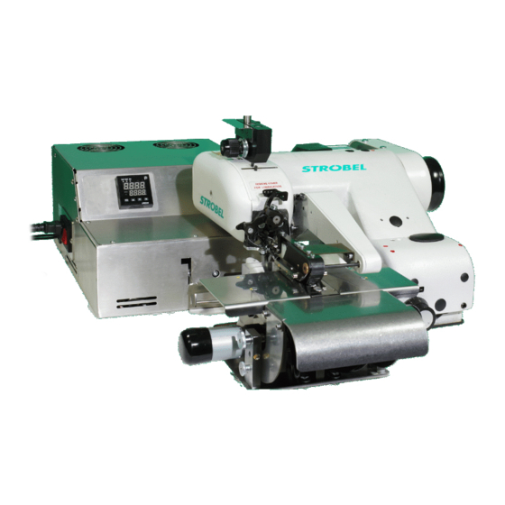
- Page 1 For the professional user Operating Instructions Für den professionellen Anwender Betriebsanleitung Class: VEB100-7 Klasse: Model: Ausführung: Dated: Stand: S p e z i a l m a s c h i n e n G m b H...
- Page 2 The sign of quality ou find the Strobel trademark on every Strobel machine leaving our works. And with good reason. This symbol is a guarantee of the high quality of our products. Quality which creates trust – trust in our technology, our service and, not least of all, in our good name.
- Page 3 Justify your trust. If you wish to profit from the performance and efficiency of your Strobel machine as long as possible, exact handling and thorough care is necessary. For this reason we kindly request that you read the operating instructions closely.
-
Page 5: Table Of Contents
Operating instructions STROBEL Class VEB100-7 Contents General notes on safety .................... 3 General ........................5 Operating instructions ..................5 Class identification, serial number and orientation of the machine ....5 Range of applications ..................5 Technical data ....................6 Installation and putting into service ................8 Unpacking the machine (Fig. - Page 6 Operating the machine .................... 21 Switching on ....................21 Placing and removing the fabric - sewing process ........21 Sewing belt loops ..................22 5.3.1 Setting stitch depth and thread tension ..........23 Quick hemmer changing device ..............24 Setting the hemmer ..................26 Fusible tapes ....................
-
Page 7: General Notes On Safety
General notes on safety Every person in charge of setting up, operating, servicing and repairing the machine must first read and understand the operating instructions and particularly the safety instructions before starting up the machine. Failure to comply with the following safety instructions can lead to bodily injury or damage to the machine. - Page 8 14. Warning instructions given in the operating instructions that pertain to especially dangerous parts of the machine must be indicated at these positions using a safety symbol. Warning instructions given in the operating instructions that pertain to special injury hazards for operating personnel or technicians must be indicated at these positions using a safety symbol.
-
Page 9: General
Range of applications Class VEB100-7 is suitable for sewing belt loops from waste fabric. The cutting device trims the material automatically to the size for the 9.5 and 11 mm hemmer. -
Page 10: Technical Data
Technical data Recommended rated speed 1800 min Motor power 550 W Toothed belt pulley/machine Z = 38 Toothed belt profile HTD 5M-9 Stitch length 3 - 6 mm (depend on fabric) Kind of stitch single thread chainstitch blindstitch Stitch type Needle system GROZ-BECKERT 1669 EEO Needle size... - Page 11 Fig. 1 BA_VEB100-7_A4_180618_en...
-
Page 12: Installation And Putting Into Service
Installation and putting into service Unpacking the machine (Fig. 1) If the pressing unit is supplied together with a Class VEB100-7 it is screwed onto the table top behind the blindstitching machine. Make sure that all accessories have been unpacked before throwing away any packing material. - Page 13 Fig. 2 BA_VEB100-7_A4_180618_en...
- Page 14 Pressing unit: The pressing unit has to be connected to an additional central steam unit with interconnected solenoid valve or to a steam generator. Attention: To avoid condensation water it is recommended to use a short teflon hose (approx. 2.5 m max.) with small diameter. And the hose should not sag to avoid that condensation water is collected.
-
Page 15: Sense Of Rotation
Sense of rotation The correct sense of rotation of the hand wheel is clockwise in line of vision on the hand wheel. Motor drive using tooth belts 3.4.1 Tension of toothed belt (Fig. 3) C A U T I O N ! Danger of injury! Switch off the machine at the mains when checking the belt tension. -
Page 16: Machine Positions (Fig. 4)
3.4.2 Machine positions (Fig. 4) C A U T I O N ! . Danger of injury! Entanglement hazard for clothing or hair and danger of finger injuries and needle punctures! When checking the positions while the machine is turned on, keep your fingers and hands away from moving parts. -
Page 17: The Feed (Fig. 5 And Fig. 6)
The feed (Fig. 5 and Fig. 6) The transport or the speed of the pressing unit is controlled automatically by the deflector roll ( Fig. 5) (1). (see also “4.8.1 Adjusting the stitch length“) After the needle plate, the loop of the belt has to be routed through underneath the deflector roll before it is fed into the opening of the pressing unit. - Page 18 Fig. 6 BA_VEB100-7_A4_180618_en...
-
Page 19: Instructions For Use
Instructions for use Needles and threads The sewing quality can be influenced to a considerable extent by choosing the most suitable needles and threads for the material to be sewn. It is recommended to use controlled GROZ-BECKERT needles system 1669 EEO only. -
Page 20: Threading And Straight Grain
Fig. 7 Threading and straight grain C A U T I O N ! Danger of injury! Switch off machine electrically and confirm that the machine is really in standstill position by operating the treadle for the motor control before threading. Otherwise danger of finger bruises and needle throughstitches. -
Page 21: Thread Tension
Thread tension Depending on thread and fabric quality, nature and thickness the thread tension is set by tension nut (1) ( Fig. 8). Thread take-up lever The thread take-up lever (2) Fig. 8 avoids thread twist and turning over of the loop, thus enabling a secure taking up of the loop by looper and needle. -
Page 22: Cloth Retainer
Cloth retainer A t t e n t i o n ! Danger of finger bruises through unintended actuation of the treadle during setting works in the needle plate area. The machine has no real cloth retainer. During the time of needle penetration the material is hold between hemmer and plunger. -
Page 23: Sewing Material Transport
Sewing material transport The machine transports the sewing material using a rigid upper transport. The feed (stitch length) can be set from 3 - 6 mm in 4 steps. Serially, a pyramid- toothed feed dog is mounted, which can be exchanged for a saw-toothed one if necessary. -
Page 24: Adjusting The Top Feed
4.8.2 Adjusting the top feed The transporter can be adjusted in its intrusion depth to the needle plate by loosening the two fastening screws. If the stitch length is adjusted across a greater range e.g., from 6 to 3 mm, then the feed dog should be readjusted. Adjustments might also be required when changing to sewing materials that are thicker or otherwise different in quality. -
Page 25: Operating The Machine
Operating the machine C A U T I O N ! Danger of injury! Please observe the sewing area carefully during sewing. Otherwise danger of finger bruises and needle throughstitches. Switching on Connect the compressed-air conditioner to the compressed air supplier (10 bar) or to the compressor and set it to 3 - 4 bar. -
Page 26: Sewing Belt Loops
Fig. 11 Sewing belt loops There is a number of hemmers available to sew nearly all required fabrics. In general, the belt loops are sewn of the waste fabrics of the trouser production. In the hemmer the fabric is symmetrically folded and centrically blindstitched. Using a tape facilitates the sewing and reinforces the belt loop. -
Page 27: Setting Stitch Depth And Thread Tension
Fig. 12 Attention: very fuzzy fabrics may disturb the process. The cuttings fall down into a garbage chute. The material is trimmed exactly and then guided to the hemmer. The tape is manually pushed through the bow at the swivelled down tape feeding device and then through the hemmer’s bow into the hemmer. -
Page 28: Quick Hemmer Changing Device
Quick hemmer changing device C A U T I O N ! Danger of injury! When working on the cutting system, switch off the power to the complete machine. Otherwise there is a danger of fingers getting crushed or cut! The hemmers are screwed to a holder and were set at works. - Page 29 Fig. 14 When the hemmer is exchanged, the height of the hemmer in relation to the curved knife needs to be checked and adjusted if necessary. Turn the knurled screw (1) for this until the correct setting has been made. BA_VEB100-7_A4_180618_en...
-
Page 30: Setting The Hemmer
Setting the hemmer The hemmer lies on the plunger with the belt loop folded on one side already, i.e. that the fabric is hold for the needle penetration and the set stitch depth is ensured. Therefore the hemmer is slotted at the front part. The hemmer’s outlet should be approx. -
Page 31: Fusible Tapes
Fusible tapes It is recommended to provide the belt loops with a fusible tape. Choose the tape width according to the following chart: hemmer size tape width inch inch 8,5-9 5/16 7/16 10-10,5 Tapes of the most different qualities can be used. Tapes coated on one side only or on both sides are used with the fabric when pressing the ready sewn belt loop. -
Page 32: Cutting System
Cutting system The cutting system with integrated quick hemmer changing device is mounted to the table plate as the standard hemmer support. The operation is supported by an additional tape feed ( Fig. 11). The cutting system needs to be cleaned regularly. See also point “6 Machine maintenance”... - Page 33 Fig. 16 Please use the following chart for the cutting widths at the knives’ cutting edges: hemmer size trimming width inch inch 28,5 1 1/8 7/16 1 5/16 The trimming width can be set from 23 to 55 mm. BA_VEB100-7_A4_180618_en...
-
Page 34: Pressing Unit
Pressing unit C A U T I O N ! Danger of injury! When working on the pressing unit, switch off the power to the entire machine, disconnect the pneumatic supply and allow the device to cool down. Otherwise there is a danger of fingers getting crushed, scalding and electric shock! 5.8.1 General... - Page 35 Fig. 18 Passage for steam connection Belt loop outlet Fig. 19 Blower connection Steam connection Step motor Pneumatic cylinder BA_VEB100-7_A4_180618_en...
-
Page 36: Switch On The Pressing Unit (Fig. 17)
5.8.2 Switch on the pressing unit (Fig. 17) Once the technician has duly mounted all air, steam and current connecting cables the unit can be put into operation as follows: The pressing unit itself is switched on at the pressing unit on the left side. The pressing unit is ready once the set temperature is reached. -
Page 37: Interruption Of The Sewing Process
5.8.5 Interruption of the sewing process The ironing shoe is lifted when the sewing and ironing machine is switched on. A built-in temperature regulator keeps the set temperature at about ±20 ºC constant. Please switch off the ironing device during longer interruptions of sewing with I/0 switch (1) (as Fig. -
Page 38: Problems During Sewing And Possible Solutions
Problems during sewing and possible solutions C A U T I O N ! Danger of injury! Switch off machine electrically and confirm that the machine is really in standstill position by operating the treadle for the motor control. Otherwise danger of finger bruises and needle throughstitches. - Page 39 Unintended skip stitching Possible reasons: wrong looper setting wrong setting of loop stroke/needle stroke, therefore insufficient loop formation (small/big) Solutions: operate machine manually, check the looper motion check the settings, re-set, if necessary, replace damaged parts change thread feed through thread take-up, if necessary ...
- Page 40 Material feed problems (stitch length different from settings) Possible reasons: feed dog setting is not correct, material cannot be caught sufficiently. unsuitable feed dog toothing feed plate lift is blocked material accumulation in the needle plate seam or loop are caught by the feed dog unintended stitch length modification Solutions: check feed dog setting and stitch length, replace feed dog, if...
-
Page 41: Machine Maintenance
Machine maintenance Most of the bearings of the machine are maintenancefree. Apply one drop of sewing machine oil (oil is supplied wit the accessories) every 20 operating hours or at least once a week to the red marked points and oil borings. Release the machine head's slotted pan-head screw and remove cover to lubricate looper link and the feed crank. - Page 42 Cl. VEB100-7 Hemmer Thin fabric 386.0441 386.0444 Standard Optional part 386.0442 386.0445 Medium fabric Standard Optional part 386.0443 386.0446 Thick fabric Optional part Optional part 9.5 mm 11 mm Hemmer size 3/8″ 7/16″ Feed dog 182.0299 182.0300 Standard Optional part...
-
Page 43: Optional Parts
Optional parts The following devices are available as optional extras and can be ordered together with the machine or as separate kits. Digital display 392.0637 Hemmer More hemmer sizes on request. BA_VEB100-7_A4_180618_en... - Page 45 Und wir können noch mehr für Sie tun! Unser Lieferprogramm bietet für jede Branche und jegliche Anforderung genau die richtige Problemlösung. And we can do a lot more for you! Our range offers the correct problem solution for every branch and for all requirements. Für die Bekleidungs- Für die Schuh- Für die Polster-...
- Page 46 Then phone, write or simply come and see us. You can have further information about our products at any time, or experience the Strobel machines live in our show room. We’re looking forward to meeting you! Spe zi a l ma s c hine n G m bH...
Need help?
Do you have a question about the VEB100-7 and is the answer not in the manual?
Questions and answers