
Related Manuals for Strobel VEB100-7


Summary of Contents for Strobel VEB100-7
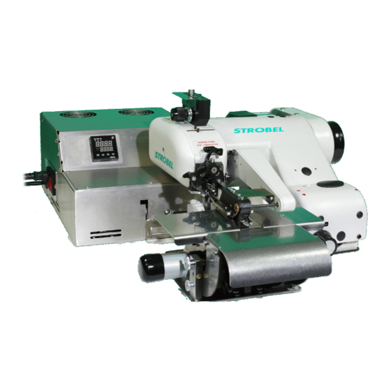
- Page 1 For the professional user Mechanic‘s Instructions Für den professionellen Anwender Mechanikeranleitung Class: VEB100-7 Klasse: Model: Ausführung: Dated: Stand: S p e z i a l m a s c h i n e n G m b H...
- Page 2 The sign of quality ou find the Strobel trademark on every Strobel machine leaving our works. And with good reason. This symbol is a guarantee of the high quality of our products. Quality which creates trust – trust in our technology, our service and, not least of all, in our good name.
- Page 3 Justify your trust. If you wish to profit from the performance and efficiency of your Strobel machine as long as possible, exact handling and thorough care is necessary. For this reason we kindly request that you read the operating instructions closely.
-
Page 5: Table Of Contents
Mechanic's instructions STROBEL Class VEB100-7 Contents Inhaltsverzeichnis General notes on safety .................... 5 General ........................7 Operating instructions ..................7 Class identification, serial number and orientation of the machine....7 Range of applications ..................7 Technical data ....................8 Setting instructions in brief ................9 Hints for repair and settings .................. - Page 6 Pressing unit......................22 General ......................22 Disassembly of the cover (Fig. 16) ............... 24 Adjusting the feed dog .................. 24 Changing the flat belt ..................25 Using sliding means ..................26 Using heat conducting paste ................ 26 Cooling air ....................26 Cutting system ......................
- Page 7 Connecting the sewing machine: 258.21.63 Electrical connection plan cl. 45, 58, 103, 120, 170, VEB 258.10.23 Electrical diagram (24VDC) cl. VEB100-7 from version 2 258.21.74 Electrical connection diagram cl. VEB100-7 distribution box 258.30.27 Electrical assembly diagram cl. VEB100-7 distribution box Connecting Pneumatic: 259.00.64...
- Page 8 MA_VEB100-7_A4_181015_en...
-
Page 9: General Notes On Safety
General notes on safety Every person in charge of setting up, operating, servicing and repairing the machine must first read and understand the operating instructions and particularly the safety instructions before starting up the machine. Failure to comply with the following safety instructions can lead to bodily injury or damage to the machine. - Page 10 14. Warning instructions given in the operating instructions that pertain to especially dangerous parts of the machine must be indicated at these positions using a safety symbol. Warning instructions given in the operating instructions that pertain to special injury hazards for operating personnel or technicians must be indicated at these positions using a safety symbol.
-
Page 11: General
11 mm hemmer. The supply of the sewing materials occurs by means of tape feed. The integradet pressing unit presses the belt loops sewn on Class VEB100-7. The steam can be supplied either by means of a central steam generating unit with interconnected solenoid valve box including condenser and steam trap or by means of a steam generator. -
Page 12: Technical Data
Technical data Recommended rated speed 1800 min Motor power 550 W Toothed belt pulley/machine Z = 38 Toothed belt profile HTD 5M-9 Stitch length 3 - 6 mm (depend on fabric) Kind of stitch single thread chainstitch blindstitch Stitch type Needle system GROZ-BECKERT 1669 EEO Needle size... -
Page 13: Setting Instructions In Brief
Setting instructions in brief Theoretic needle radius 41.3 mm Left needle guide 41.33 +0.02 mm Needle glide plate 41.30 ±0.01 mm Right needle guide 41.40 +0.05 mm Needle strike, needle eye to looper finger 1.5 +0.5 mm Ball pin to needle shaft 4 ±0.50 mm approx. -
Page 14: Hints For Repair And Settings
Hints for repair and settings C A U T I O N ! Danger of injury! Observe safety and operating instructions before realizing any maintenance and repair works. Failure to do so may result in heavy bodily injuries. Mounting the needle plate A t t e n t i o n ! Switch off machine electrically! Needle plates are set at works and can be replaced easily as complete kit. -
Page 15: Removing The Needle Plate (Fig. 1)
3.1.1 Removing the needle plate (Fig. 1) Switch off machine electrically, cloth support arm is lifted. Remove needle and needle lever. Release needle plate (1) fastening screws (2) and remove the complete needle plate unit to the front. 3.1.2 Remounting the needle plate Amount the needle plate in reversed order but make sure that the needle plate opening is mounted centrically to the plunger foot and that the needle plate is mounted horizontally. -
Page 16: Needle Lever
Needle lever 3.2.1 Mounting A t t e n t i o n ! Switch off machine electrically! Release screw (1), swivel the thread take-up and remove the needle lever. When mounting the needle lever make sure that the needle is mounted centrically to the needle channel and that the needle point is flush with the right hand edge of the left hand needle guide (Fig. -
Page 17: Setting The Needle Stroke (Fig. 3 And Fig. 4)
3.2.2 Setting the needle stroke (Fig. 3 and Fig. 4) Set the needle stroke in a way that at a loop stroke of 2.8 + 0.3 mm the left side of the needle eye has a distance of approx. 1.5 +0.5 mm to the right hand edge of the large looper finger, the point of the large looper finger being above needle center ( Fig. -
Page 18: Loop Stroke
Loop stroke The loop stroke is the needle's way from its right cusp point to the point where the point of the large looper finger is placed above needle center Fig. 5). Fig. 5 3.3.1 Setting the loop stroke A t t e n t i o n ! Switch off machine electrically! At factory the loop stroke is set to 2.8 +0.3 mm (Fig. -
Page 19: Looper
Looper 3.4.1 Removing and remounting the looper (Fig. 4) A t t e n t i o n ! Switch off machine electrically! Release cap screw (11) and pull the looper towards the front. When remounting the looper make sure that it is completely pushed in and that its positioning surface fits exactly to the looper take-up. -
Page 20: Setting The Looper (Fig. 4, Fig. 5 And Fig. 7)
3.4.4 Setting the looper (Fig. 4, Fig. 5 and Fig. 7) In the moment of the loop take-up the looper fingers should be placed 0.1 - 0.2 mm above the needle, also when a thicker needle is used. The needle should not be touched! The horizontal distance from the large looper finger to the needle eye should be 1.5 +0.5 mm (Fig. -
Page 21: Feed Dog (Top Feed)
Feed dog (top feed) The machine is equipped with a pyramid-teethed feed dog. Its movement in relation to the needle plate can be adjusted after releasing screws. Or it can be replaced by saw-teethed feed dog. 3.5.1 Setting the feed dog (Fig. 8) A t t e n t i o n ! Switch off machine electrically! Clamp the feed dog so that it is parallel to the needle plate and that it shows the... -
Page 22: Feed Plates
Feed plates 3.6.1 Setting the feed plate A t t e n t i o n ! Switch off machine electrically! The feed plate position is given by the symmetrical position of the angle levers to the plunger. They should tilt easily and fit closely to the needle plate. The pressure is approx. -
Page 23: Plunger
Plunger A t t e n t i o n ! Switch off machine electrically! The VEB100-7 is equipped with a rigid, roof-shaped plunger of radius 24.5 mm. 3.7.1 Replacing the plunger shaft (Fig. 9) Remove cloth support arm extension (2). -
Page 24: Adjusting The Plunger (Fig. 10)
3.7.2 Adjusting the plunger (Fig. 10) Remove the clamping screw on lever (4) Fig. 9. For blind stitches, the adjustment must be made according to Fig. 10a for thick materials and Fig. 10b for thin materials. The plunger is situated in the centre of the needle plate opening and is usually offset by 1 mm to the left of the needle shaft’s centre. -
Page 25: Adjusting The Material Support Arm
3.7.3 Adjusting the material support arm Turn the main shaft until the needle tip stands 1–2 mm behind the centre of the plunger. Adjust the control knob (1) Fig. 12 so that the needle is lifted by 0.2 mm, then screw in the threaded pin (2) Fig. 12 until it lies against the case. Next, counter the threaded pin (3) Fig. -
Page 26: Pressing Unit
Pressing unit C A U T I O N ! Danger of injury! When working on the pressing unit, switch off the power to the completemachine, disconnect the pneumatic supply and allow the device to cool down. Otherwise there is a danger of fingers getting crushed, scalding and electric shock! General... - Page 27 Fig. 14 Passage for steam connection Belt loop outlet Fig. 15 Blower connection Steam connection Step motor Pneumatic cylinder MA_VEB100-7_A4_181015_en...
-
Page 28: Disassembly Of The Cover (Fig. 16)
Disassembly of the cover (Fig. 16) Loosen the screws so that the two panels (1) and (2) can be removed. Fig. 16 Adjusting the feed dog The transport or the speed of the pressing unit is controlled automatically by the deflector roll ( Fig. -
Page 29: Changing The Flat Belt
Changing the flat belt C A U T I O N ! Danger of injury! When working on the pressing unit, switch off the power to the completemachine, disconnect the pneumatic supply and allow the device to cool down. Otherwise there is a danger of fingers getting crushed, scalding and electric shock! Loosen the screws so that the two panels (Fig. -
Page 30: Using Sliding Means
The flat belt can be exchanged (Fig. 19 (1)) by pressing the base of the press together. The base of the press can be re-installed in reverse order. The running (centrally/straight) of the flat belt can be set at the screw (Fig. 19 (2)). -
Page 31: Cutting System
Cutting system C A U T I O N ! Danger of injury! When working on the cutting system, switch off the power to the complete machine. Otherwise there is a danger of fingers getting crushed or cut! General 5.1.1 Note on the service life of the knifes The greater the setting of the contact pressure and the greater the setting angle, the greater the wear of the knife is, which reduces the service life. -
Page 32: Installing And Disassembling The Complete Knife Holder
Installing and disassembling the complete knife holder C A U T I O N ! Danger of injury! When working on the cutting system, switch off the power to the complete machine. Otherwise there is a danger of fingers getting crushed or cut! 5.2.1 Removing the complete knife holder (Fig. -
Page 33: Installing The Complete Knife Holder (Fig. 21, Fig. 22 And Fig. 23)
5.2.2 Installing the complete knife holder (Fig. 21, Fig. 22 and Fig. 23) Carry out the installation in the reverse order of the disassembly. ( Fig. 20) During installation, also pay attention to the axial play of the connecting rod to the curved knife when the journal (1) is inserted in the curved knife (8). - Page 34 Check the axial play by turning the eccentric on the connecting rod (3) by 360° with your finger. You thereby check the axial play between journal (1) and curved knife (2). Axial play has to be present in every position of the connecting rod (3).
-
Page 35: Setting The Knifes
Setting the knifes C A U T I O N ! Danger of injury! When working on the cutting system, switch off the power to the complete machine. Otherwise there is a danger of fingers getting crushed or cut! Only the setting of the left knife is described here as the right knife is constructed in mirror fashion. - Page 36 Fig. 25 Screw in the threaded pin (1) until it protrudes by 0.6 mm on the side where the curved knife contacts. (Fig. 26) The 0.6 mm serve as a guideline. Fig. 26 MA_VEB100-7_A4_181015_en...
-
Page 37: Setting The Setting Angle
5.3.2 Setting the setting angle The setting angle of the curved knife to the knife can be set at the right threaded pin (2) / nut (2). ( Fig. 24) Screw in = wider angle = more wear Screw out = narrower angle = less wear The curved knife needs to be removed for this setting. - Page 38 Fig. 27 Position 2 (Fig. 28 In this position, the contact plate should have no contact with the curved knife (= small gap); this should occur by itself, if not, then position 1 needs to be readjusted. Fig. 28 MA_VEB100-7_A4_181015_en...
- Page 39 258.00.35 Netz-Anschlussplan Kl. allg. (AB611A mit/ohne Nähleuchte allg.) Mains connection plan cl. gen. (AB611A with/without sewing light gen.) Kabelbefestigung mit Kabelbinder cable mounting with cable strap Nähleuchte (allg.) 3x 293.0290 sewing light (gen.) Kabelzugentlastung cable strain relief 193.0992 Netzanschluss Rechtes Gehäuseteil power connection right casing gn-ge / gn-ye...
-
Page 40: Electrical Connection Plan Cl. 45, 58, 103, 120, 170, Veb
LÜ ( MV1 ) 6,5A +24V(1) +24V(1) Control box Efka drive (1) Nominal voltage 24V, idle voltage max. 30V Designation Designation Colour code 37 pin Strobel operating manual Efka operating manual connection cable Sub-D Thread trimmer (FA) Output 1 (M1) yellow brown... - Page 41 258.10.23en Electrical wiring diagram cl. VEB100-7 as of version 2 front plate switch box pressing unit 24VDC X14 (ST2) 24V= / brown 0V / white X2-1 X2-6 X2-2 X2-4 green X2-3 X2-5 from sewing drive distribution box 24VDC -circuit terminal 195.0053...
-
Page 42: Electrical Connection Diagram Cl. Veb100-7 Distribution Box
258.21.74 Elektrischer Anschlussplan Kl. VEB100-7 - Verteilerkasten Electrical connection diagram cl. VEB100-7 - distribution box 195.0058... -
Page 43: Electrical Assembly Diagram Cl. Veb100-7 Distribution Box
258.30.27 Elektrischer Bauschaltplan Kl. VEB100-7 - Verteilerkasten Electrical assembly diagram cl. VEB100-7 - distributing box Steuerung control box Magnetventil solenoid valve Schneidstation 2x cutting station 2x Dampfgenerator steam generator Relais relay... -
Page 44: Pneumatic Circuit Diagram Cl. Veb100-7
259.00.64 Pneumatischer Schaltplan Kl. VEB100-7 Pneumatic circuit diagram cl. VEB100-7 1 A 1 1 V 10 1 V 1 0 Z 1 6bar 10bar max 195.0545 0 Z 1 Wartungseinheit service unit 1 V 1 4/2-Magnetventil "Trocknung"/"Lüftung Bügelstation" 4/2-solenoid-way valve "drying"/"lifting pressing unit"... -
Page 45: Pneumatic Construction Circuit Diagram Cl. Veb100-7
259.10.64en Pneumatic construction circuit diagram cl. VEB100-7 195.0546... - Page 47 Und wir können noch mehr für Sie tun! Unser Lieferprogramm bietet für jede Branche und jegliche Anforderung genau die richtige Problemlösung. And we can do a lot more for you! Our range offers the correct problem solution for every branch and for all requirements. Für die Bekleidungs- Für die Schuh- Für die Polster-...
- Page 48 Then phone, write or simply come and see us. You can have further information about our products at any time, or experience the Strobel machines live in our show room. We’re looking forward to meeting you! Spe zi a l ma s c hine n G m bH...
Need help?
Do you have a question about the VEB100-7 and is the answer not in the manual?
Questions and answers