SUTO S 551 Series Instruction And Operation Manual
Compressed air analyser
Hide thumbs
Also See for S 551 Series:
- Instruction and operation manual (36 pages) ,
- Instruction and operation manual (36 pages)
Table of Contents
Advertisement
Quick Links
Advertisement
Table of Contents

Related Manuals for SUTO S 551 Series


Summary of Contents for SUTO S 551 Series
- Page 1 English Instruction and operation manual S 551 Compressed air analyser...
- Page 2 The device is destined exclusively for the described application. SUTO offers no guarantee for the suitability for any other purpose. SUTO is also not liable for consequential damage resulting from the delivery, capability or use of this device.
-
Page 3: Table Of Contents
Table of contents 1. Safety instructions...............5 2. Application.................7 3. Features..................7 4. Technical Data................8 4.1 General.................8 4.2 Electrical Data................8 4.3 Input-Signals.................8 4.4 Output-Signals...............8 5. Installation ................9 5.1 Installation Requirements............9 5.2 Installation Procedure ............9 5.3 Electrical connection ............10 6. Configuration ................13 7. Operation ................13 7.1 Value screen................14 7.2 The main menu ..............15 7.3 Description of display icons in status bar .........16... - Page 4 14. Warranty................29 S 551...
-
Page 5: Safety Instructions
1. Safety instructions 1. Safety instructions Please check if this instruction manual accords to the product type. Please observe all notes and instructions indicated in this manual. It contains essential information which have to be observed before and during installation, operation and maintenance. - Page 6 1. Safety instructions WARNING! Permitted operating parameters! Observe the permitted operating parameters, any operation exceeding this parameters can lead to malfunctions and may lead to damage on the instrument or the system. • Do not exceed the permitted operating parameters. •...
-
Page 7: Application
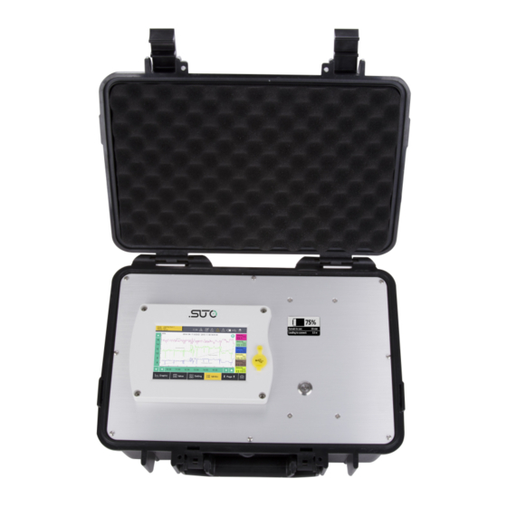
1. Safety instructions • Avoid direct UV and solar radiation during storage. • For the storage the humidity has to be <90%, no condensation. 2. Application The S 551 is a compressed air analyser which is designed to display and record all relevant parameters of compressed air and gases within the permissible operating parameters. -
Page 8: Technical Data
4. Technical Data 4. Technical Data 4.1 General Data logger 4 GB, up to 100 million values Operating temperature 0°C... 50°C Housing material PC + ABS Protection class IP 65 Dimensions 365 mm x 270 mm x 169 mm Display 5”... -
Page 9: Installation
5. Installation 5. Installation Please make sure that all components listed below are included in your package. Qty Description Item No. S 551-P4 / S 551-P6 P560 5100/5101 USB cable A553 0130 Instruction manual No P/N Calibration certificate 5.1 Installation Requirements ATTENTION! Wrong measurement is possible, if the device is not installed correctly. -
Page 10: Electrical Connection
5. Installation 5.3 Electrical connection Please connect all sensors before switch on the S 551. Flow / dew point sensors are detected automatically when connected. The same extension modules ( power meter, US flow meter, analog extension) which are connected to terminal M. Process signals can not be detected automatically. - Page 11 5. Installation To connect the different sensors please have a look to the designed terminal. Connector Connector Connector Connector Dew point/ Modbus / Pulse Pulse Signal Signal Signal Colour flow sensor active passive +I / Pulse brown 20 mA white blue black grey...
- Page 12 5. Installation In case the user want to connect other analog sensors such as 0...20 mA, 4... 20 mA, 0... 1 V, 0... 10 V and pulse types, this can be done trough connector 3-4 according to pinning shown in the table above. The S 551 can also supply the external sensor with 24 VDC.
-
Page 13: Configuration
5. Installation Sensors powered by S 551 The S 551 can supply 24 VDC to external sensors and a total power of 20 W. All sensors connected to S 551 and supplied by S 551 must not exceed this power limit. To determine the power consumption please use the table below: Sensor Power... -
Page 14: Value Screen
7. Operation When the S 551 starts up it will display the start up screen for a few seconds. During this time the sensor connections are established and a few other initialisation tasks are performed. 7.1 Value screen The S 551 will connect automatically to the connected sensors and starts to display the real time measurement values. -
Page 15: The Main Menu
7. Operation 7.2 The main menu Status Function buttons Quick buttons The menu consists of the following sub-menus: Sensor settings Settings related to the connected sensors. Logger S 551 data logger settings. Files All recorded files and the memory status can be checked. -
Page 16: Description Of Display Icons In Status Bar
7. Operation 7.3 Description of display icons in status bar USB stick connected System error Sensor connection has Sensor unit is not changed, not matching matching with with configuration configuration RTC backup battery Logger status status Sensor calibration is USB to PC connected expired Alarm triggered 7.4 Graphic screen... -
Page 17: Sensor Setting
7. Operation 7.5 Sensor setting The following chapters describe the available settings of the different sensors. The sensor setting menu allows specific settings at the connected sensor. After selecting of “Sensor setting”, the next screen will show which kind of sensors are programmed. Changes can be done individually for each sensor, by selecting the related sensor. - Page 18 7. Operation Dew point Dew point sensor can be adjust at one point a cali. reference value. We recommend to do this calibration only below -40°C dew point and by using a reliable reference. Pressure Some dew point sensor have integrated pressure calibration sensors which can be calibrated in the dialogue.
-
Page 19: Flow Sensor Setting
7. Operation 7.5.2 Flow sensor setting S 551... - Page 20 7. Operation Analog output Select physical flow unit and set scaling of analog output: whenever the flow unit is changes, it is recommended to adjust the scaling of the analog output. The S 551 will recommend a standard scaling. The scaling is used to express the flow through a 4...
-
Page 21: Oil Vapor Sensor Setting
7. Operation 7.5.3 Oil vapor sensor setting Basic setting Altitude: please enter the altitude level, default is 0. User slope: allows a correction of the oil content by a factor. Compressor oil: select oil type, which is under measurement. Output unit: select unit of oil content. Analog output Set scaling of analog output (4... -
Page 22: Analog Input Setting
7. Operation 7.5.4 Analog input setting The S 551 has optional two analog input channel for various analog signals (4... 20 mA, 0... 10 V, etc.). These channel have to be prepared by S4C software. The following settings are available on the interface of S 551: Basic setting Sensor description: enter a sensor name. -
Page 23: Power Meter S 110-P Setting
7. Operation connected to the terminal which was used for calibration. Make sure if other sensors are connected, that the calibration offset is deleted. Ch 2 setting Measure type: only counter is selectable. (counter only) Description: enter a channel name. Predefine unit: select a physical unit. -
Page 24: Logger
7. Operation 7.6 Logger In this sub-menu the logger status can be seen and programmed. Start time Logger start time Sample / Recorded sample number per logging channel Channel Logger channel Total recording channel number Sample rate Recording interval Status Logger status S 551... -
Page 25: Files
7. Operation 7.7 Files This menu shows all recorded files. Single files can be selected for some recording details or can be deleted. Memory status inform about available memory. 7.8 Service info Contact information of service company can be set via CSC software S 551... -
Page 26: System Setting
7. Operation 7.9 System setting Varicose system settings can be done under this menu. Just click press related buttons and following the instruction. Password Set password to protect some critical operations Back light Adjust brightens and dimming time out. Calibrate touch Calibrate touch accuracy screen Language... - Page 27 7. Operation Web server The S 551 can send out actual measurement and status information to a PC with fix domain name or IP address. By using our S4M-XL software on this PC a remote monitoring of the system can be achieved. Please contact your retailer or the manufacturer for further information.
-
Page 28: Signal Inputs
8. Signal inputs 8. Signal inputs 8.1 Digital inputs The analyser has two different digital inputs: • 2 x SDI Sensors • 16 x RS 485 Modbus RTU Sensors 8.2 Analog input In case the user want to connect other analog sensors the analyser has two optional analog / pulse inputs: •... -
Page 29: Calibration
14. Warranty SUTO provides a warranty for this product of 24 months covering the material and workmanship under the stated operating conditions from the date of delivery. Please report any findings immediately and within the warranty time. - Page 30 14. Warranty ◦ Use of unsuitable accessories. ◦ External influences (e.g. damage caused by vibration, damage during transportation, excess heat or moisture). S 551...
- Page 31 14. Warranty The warranty is cancelled: • If the user opens the measurement instrument without a direct request written in this instruction manual. • If repairs or modifications are undertaken by third parties or unauthorised persons. • If the serial number has been changed, damaged or removed. Other claims, especially those for damage occurring outside the instrument are not included unless responsibility is legally binding.
- Page 32 S 551...
- Page 33 SUTO iTEC GmbH SUTO iTEC Co., Ltd. Werkstr. 2 Room 10, 6/F, Block B, Cambridge Plaza 79426 Buggingen 188 San Wan Road, Sheung Shui, N.T. Germany Hong Kong Tel: +49 (0) 7631 936889-0 Tel: +852 2328 9782 Fax: +49 (0) 7631 936889-19...
Need help?
Do you have a question about the S 551 Series and is the answer not in the manual?
Questions and answers