SUTO S551 Instruction And Operation Manual
Portable data logger
Hide thumbs
Also See for S551:
- Instruction and operation manual (36 pages) ,
- Instruction and operation manual (33 pages)
Table of Contents
Advertisement
Quick Links
Advertisement
Table of Contents

Related Manuals for SUTO S551


Summary of Contents for SUTO S551
- Page 1 English Instruction and operation manual S551 Portable data logger...
- Page 2 The device is designed exclusively for the described application. SUTO offers no guarantee for the suitability for any other purpose. SUTO is also not liable for consequential damage resulting from the delivery, capability or use of this device.
-
Page 3: Table Of Contents
5.3 Signal inputs................9 5.4 Signal outputs..............9 6 Installation ................10 6.1 Installation Requirements.............10 6.2 Connectors on the case............11 6.3 Electrical connection............14 6.3.1 Sensors powered by S551 ..........14 6.3.2 Electrical connection............15 7 Configuration ................15 8 Operation ................16 8.1 Value screen...............16 8.2 Menu ................17 8.3 Icons in the status bar ............18... - Page 4 10.2 Analog input ..............33 11 Signal outputs.................33 12 Optional accessories..............33 13 Calibration................34 14 Maintenance................34 15 Disposal or waste..............34 S551...
-
Page 5: Safety Instructions
• Consider all regulations for electrical installations. • The system must be disconnected from any power supply during maintenance work. • Any electrical work on the system is only allowed by authorized qualified personal. S551... - Page 6 • For transportation it is recommended to use the packaging which comes with the device. • Please make sure that the storage temperature of the device is between -20 ... +50°C. • Avoid direct UV and solar radiation during storage. S551...
-
Page 7: Registered Trademarks
1 Safety instructions • For the storage the humidity must be <90% with no condensation. 2 Registered trademarks SUTO ® Registered trademark of SUTO iTEC MODBUS ® Registered trademark of the Modbus Organization, Hopkinton, USA HART ® Registered trademark of the HART Communication... -
Page 8: Application
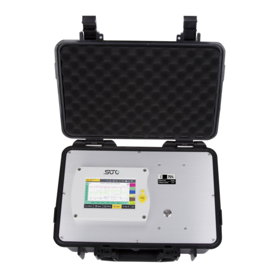
3 Application 3 Application The S551 is a portable data logger that displays and records various measurement data of compressed air and gases within the permissible operating parameters. (See Chapter 5 Technical data on the next page.) Incorporating with free or paid analysis software from SUTO, S551 enables you to analyze the measurement data in a flexible and efficient way. -
Page 9: Technical Data
5.3 Signal inputs Analog input 0 ... 1 V, 0 ... 10 V, 0 ... 20 mA, 4 ... 20 mA Digital input 2 x SDI Sensors 16 x RS-485 Modbus RTU Sensors 5.4 Signal outputs Communication Interface Ethernet, USB S551... -
Page 10: Installation
• The device is for indoor use only! At an outdoor installation, the device must be protected from solar radiation and rain. • It is strongly recommended you not install S551 permanently in wet environment such as the place right after a compressor outlet. -
Page 11: Connectors On The Case
Flow sensors: S401/421, S450/452, S430 • Dew point sensors: S220, S212, S215, S217, S201 • 3, 4 Optional. Available on the S551-P6 Connectors for process signal sensors (such as analog signal sensors and pulse sensors) M, M Connectors for the Modbus sensors and devices... - Page 12 6 Installation To connect sensors to the S551, refer to the following table for the designed connectors. Connector Connector Connector Connector Signal Signal Signal Colour Modbus / Pulse Pulse point/ flow active passive sensor +I / Brown Pulse 20 mA...
- Page 13 Legend to pin assignment Digital signal (internal use) Negative supply voltage Positive supply voltage Active 4 ... 20 mA signal Modbus Data + Modbus Data - Positive Voltage Input Not Applicable Pins of the ODU connector Connection pins (view onto the connector) S551...
-
Page 14: Electrical Connection
With the case design, the S551 does not need a costly installation. 6.3.1 Sensors powered by S551 The S551 supplies 24 VDC and totally 20 W to the connected sensors. Please make sure that the total power of all S551-powered sensors does not exceed this limit. -
Page 15: Electrical Connection
8.5.4 Analog input setting on page 24. 7 Configuration The S551 provides factory settings according to orders. All settings are stored in the S551. To change the factory settings on site, see section 8.5 Sensor settings on page 15. S551... -
Page 16: Operation
During this period, S551 detects the connected sensors and establishes the connections to sensors. 8.1 Value screen After the S551 is initialized, the measurement values from the connected sensors are displayed on the screen in the real-time. S551... -
Page 17: Menu
To enable the Specific Power (SP) channels and assign a power meter for each enabled channel. Logger To view and change the S551 data logger settings. Files To view and manage all recorded log files and the screenshots. To view the memory status. -
Page 18: Icons In The Status Bar
USB stick connected System error Sensor connection Sensor unit is not changed, not matching matching with the with the configuration configuration RTC backup battery Logger status status Sensor calibration USB to PC connected expired Connected to the Alarm triggered Internet S551... -
Page 19: Graphic Screen
4. Click Save. Changes are saved and downloaded to the sensors in the selected sensor type. Remark: The S551 can automatically detect the sensors that are manufactured by SUTO. The standard settings of these sensors are completed in factory. S551... -
Page 20: Dew Point Setting
Pressure Applicable to the dew point sensors that have pressure calibration sensors integrated. Calibrate the integrated pressure sensors. Modbus Applicable to the dew point sensors that come with the setting Modbus interface. Set the communication parameters S551... -
Page 21: Flow Sensor Setting
Shows the sensor information for service inquiries. 8.5.2 Flow sensor setting Remark: Reference pressure and reference temperature are not related to the actual process pressure or temperature. They are used to calculate the standard flow at standard conditions, for example: 1000 hPa, 20°C. S551... - Page 22 Altitude: Enter the altitude level. Default value: 0. User slope: To correct the flow by a factor, enable the user slope. Copy setting Applicable to S551-P6. Modbus Applicable to sensors with the Modbus interface. settings Set the Modbus communication parameters.
-
Page 23: Oil Vapor Sensor Setting
Shows the PID sensor lifetime, valid calibration time, remaining filter capacity (The filter is consumable component used for auto zero calibration.), gas temperature, and pressure. An indication is given at each line about whether the value is normal or not. S551... -
Page 24: Analog Input Setting
The calibration reference value will then be stored in the S551, and applied to the sensor that is connected to this channel. If you connect another sensor to this channel, make sure to delete the previous reference value. -
Page 25: Power Meter S110-P Setting
Count/pulse: Enter how many consumption units one pulse is equal to. 8.5.5 Power meter S110-P setting S110-P comes with the Modbus output. Please connect it to connector M of S551. Sensor type Select the right CT type (100 A, 1000 A, or 3000 A) Wire type... -
Page 26: Specific Power
The SP measurement is made available by having the S430 flow meters and S110-P power meters connected to the S551. An S430 can be connected to an S551 only through Connector 1 or 2. An S551 can enable two SP channels at maximum for measuring SPs for two sets of compressors. -
Page 27: Logger
Shows the total recording channel number Sample rate Shows the recording interval Status Logger status Key start To start logging immediately. Time start To configure a recording schedule Select channel To select the channel to record More setting To configure other logger settings S551... -
Page 28: Files
To view and manage all recorded files and screenshots. Single files can be selected for download or deletion. You can also check the memory status. 8.9 Service info. Shows the contact information of service company, which can be set via the S4C-Display software S551... -
Page 29: System Settings
8 Operation 8.10 System settings To configure the S551 system settings. Password To set a password to protect the settings menu from unauthorized access. Back light To configure the brightness and the auto dimming function of the screen. Calibrate touch... -
Page 30: Communication
8 Operation 8.11 Communication An S551 is provided with an Ethernet port through which the S551 communicates with application servers such as the S4M server for remote monitoring. This menu enables you to configure how S551 communicates with the peer application servers such as S4M. -
Page 31: Field-Bus Ethernet
8 Operation 8.11.2 Field-bus Ethernet When S551 communicates with the S4A or S4M server through the TCP protocol, do the following: 1. Click the Field-bus Ethernet icon. 2. Select a protocol as needed. 3. Select how the S551 is assigned with an IP address: •... -
Page 32: Application Example
SUTO's professional analysis software such as S4A, CAA, or S4M for measurement analysis. An S551 can provide two SP channels to measure SPs for two sets of compressors. To monitor the SP for a compressor, do the following: 1. -
Page 33: Signal Inputs
• 2 Modbus connectors, supporting a total of 16 x RS-485 Modbus/RTU sensors Remark: To connect a digital sensor with a digital input on the S551, please use the standard sensor cable (P/N: A553 0111). This cable is 5 m long with the M12 connector on one end (to connect a digital sensor) and the ODU connector on the other end (to connect a digital input on the S551). - Page 34 • Open-wire cable, 5 m cable with connector • Sensor cable, M12, 5 m with the ODU connector to S551 • Transport case S551 for sensors and cables, (560 x 450 x 160 13 Calibration The sensor is calibrated ex-works. The exact calibration date is printed on the certificate supplied together with the sensor.
- Page 35 S551...
- Page 36 SUTO iTEC GmbH SUTO iTEC (ASIA) Co., Ltd. Grißheimer Weg 21 Room 10, 6/F, Block B, Cambridge Plaza D-79423 Heitersheim 188 San Wan Road, Sheung Shui, N.T. Germany Hong Kong Tel: +49 (0) 7634 50488 00 Tel: +852 2328 9782...
Need help?
Do you have a question about the S551 and is the answer not in the manual?
Questions and answers