
Related Manuals for SUTO S435


Summary of Contents for SUTO S435
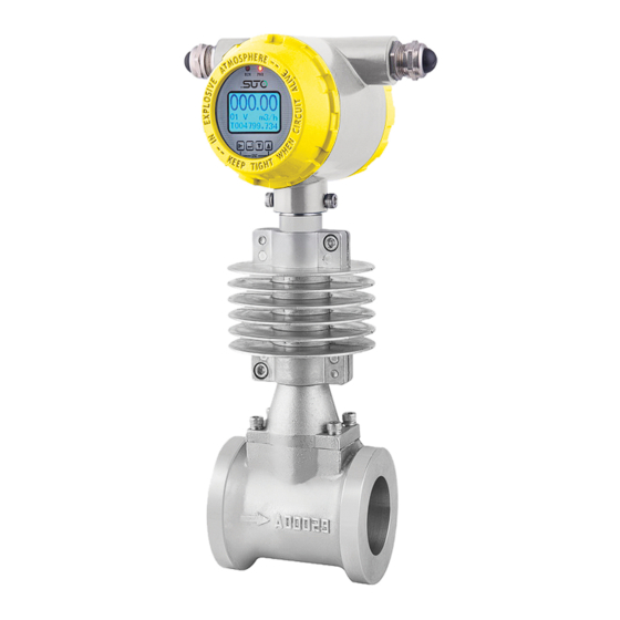
- Page 1 English Instruction and operation manual S435 Vortex Flow Meter for Steam (Inline)
- Page 2 The device is designed exclusively for the described application. SUTO offers no guarantee for the suitability for any other purpose. SUTO is also not liable for consequential damage resulting from the delivery, capability or use of this device.
-
Page 3: Table Of Contents
7.5.2 Flow Unit................23 7.5.3 LowFlow Cutoff..............23 7.5.4 Flow Range................23 7.5.5 Language................23 7.5.6 Output Mode..............23 7.5.7 Output Freq...............23 7.5.8 CommAddress ..............24 7.5.9 Band Rate.................24 7.5.10 CompensMode ..............24 7.5.11 CompSetTemp..............25 7.5.12 CompSetPress..............25 7.5.13 RTD Sel................25 7.5.14 PressMax.................25 7.5.15 VoltageMin/ VoltageMax/ Sensor Type........25 S435... - Page 4 11.3.1 Master Order Frame Structure..........32 11.3.2 Slave response frame structure...........32 11.4 Function Codes.................33 11.5 Definition of addresses..............33 11.6 Modbus Registers..............33 11.6.1 S435 Data Type..............33 11.6.2 Modbus Register Addresses..........34 11.6.3 Description of Data............36 11.7 Communication Data Analysis.............37 11.7.1 Read Instantaneous Flow...........37 11.7.2 Read Cumulative Flow............38...
-
Page 5: Safety Instructions
• Consider all regulations for electrical installations. • The system must be disconnected from any power supply during maintenance. • Any electrical work on system is allowed only by authorized qualified personal. S435... - Page 6 • Always observe the direction of the flow when installing the device. The direction is indicated on the housing. • Do not exceed the maximum operation temperature at the sensors tip. • Avoid condensation on the sensor element because it will affect accuracy enormously. S435...
-
Page 7: Registered Trademarks
• Avoid direct UV and solar radiation during storage. • The storage humidity must be between 5% … 90% with no condensation. 2 Registered Trademarks SUTO ® Registered trademark of SUTO iTEC MODBUS ® Registered trademark of the Modbus Organization, Hopkinton, USA HART ®... -
Page 8: Application
3 Application 3 Application The S435 Vortex Flow Meter for Steam operates based on the Karman Vortices principle, and is used to measure flow rates in saturated steam applications. 4 Technical Data 4.1 General Measured fluid Steam Gas Nominal diameter (mm) DN40 …... -
Page 9: Dimensional Drawing
5 Dimensional Drawing 5 Dimensional Drawing Figure 1 Outline dimensional drawing of Vortex Flow Meter for Steam Vortex Flow Meter Dimension Rated Pressure 1.6 MPa Unit: mm ΦD S435... -
Page 10: Installation
• Converter of the flow meter should be free from direct sunshine. (Shade is required) Observe the following rules when choosing the installation places: • No negative pressure in measuring tube. • Avoid being installed near motor, transformer, and other strong S435... - Page 11 • Avoid direct rain and soaked places. • Prevent liquid retention. • The flow meter should be mounted on a vertical pipe to prevent accumulation of fluid. • When the flow meter is installed horizontally, raise the pipe section installed with the flow meter. S435...
-
Page 12: Installation Instructions
1.Flow condition at the entrance shouldn’t be interfered ≥ 10D 2. Behind the valve ≥ 35D 3. Reducing pipe ≥ 15D 4. One 90° bent pipe ≥ 20D 5. Two 90° bent pipes on one flat surface ≥ 30D S435... - Page 13 1. Downstream Straight Pipe ≥ 5D 2. Measuring point away from vortex flow meter ≥ (4-6)D 3. Advice: The meter is installed upstream of the valve 4. Not advice: the meter is mounted directly behind the valve 5. Maximum height of insulation layer S435...
-
Page 14: Wafer Type Of Vortex Flow Meter Installation
When the flow meter is • installed vertically in an open position, the wiring port should face downwards, otherwise it will leak rain when it rains. S435... -
Page 15: Flange And Bolt
DN200 DN250 DN300 6.3 Electrical Connection 6.3.1 Requirements on Cable Cable Illustration According to requirement of the protection level, we advise that: Cable does not knot at the entrance, Use drip bend ( Cable U-bend to avoid water intake). S435... -
Page 16: Terminal Connection
DC 24 V+ DC 24 V- Output Current anode Output Current cathode pulse output pulse common RS-485 RS-485 Resistance Temperature Detector Signal positive Resistance Temperature Detector Signal negative Pressure sensors Power supply positive pole Pressure sensors power supply negative pole S435... -
Page 17: Power Supply Connection
0…5000 Hz, and the frequency output corresponds to the flow percentage. User can choose 0...5000 Hz, also can select a lower frequency, for example 0...1000 Hz or 0...2000 Hz, etc. POUT are transistor open collector output. Frequency output The frequency output is active digital output direct connection. S435... -
Page 18: Rs-485 Communication
In order to eliminate signal reflections in the communication cable, Parallel 120Ω termination resistor to the flow meter terminal A, B line at the end of the RS-485 which is close to the flow meter. The wiring can refer to the following: S435... -
Page 19: Parameter Setting
Up: In parameter setting status, press this key, screen can display the upper content circularly, and press this key can increase the numbers. Down: In parameter setting status, press this key, screen can display the next content circularly, and press this key can decrease the numbers. S435... - Page 20 “ENTER” to exit the menu. 5. Press “UP” or “DOWN”, choose the next menu that need to setup. After the setup, press “ENTER” for three seconds to exit the parameter setting. And press “SHIFT+UP”, return to the previous menus. S435...
-
Page 21: Parameter Setting Function And Operation
Filt Time 1 ~ 60s Flow Cutoff 0 ~ 10000 Total Reset Clear the cumulative flow Total Value 0 ~ 10000000000 Analog Test 0.0000 ~ 24.000 mA PO Test 0.0000 ~ 5000.0 Hz S435... -
Page 22: Quick Setup Menu List
7 Parameter Setting Menu Setting Description User Pwd. Set user password Information query Display the sensor information (No password) 7.4 Quick Setup Menu List S435... -
Page 23: Parameter Settings Instruction
Output frequency setting, that is, the output frequency upper limit setting; the output frequency lower limit defaults to 0, no setting is required; The output frequency setting range is (0 ~ 5000) Hz (can be set). The frequency output corresponds to the percentage of flow. S435... -
Page 24: Commaddress
10. Super_MTMP – Superheated Steam - Measure Temperature and Measure Pressure. 11. Super_MTSP – Superheated Steam - Measure Temperature and Set Pressure. 12. Super_STMP – Superheated Steam - Set Temperature and Measure Pressure. 13. Super_STSP – Superheated Steam - Set Temperature and Set Pressure. S435... -
Page 25: Compsettemp
The factory default is 101.325 kPa. For actual values, please refer to the local actual atmospheric pressure setting. 7.5.17 Press Unit The factory default is Pa, and can choose Pa, kPa, MPa. 7.5.18 Press Cut Off Cut off according to the percentage of pressure. And steady indication S435... -
Page 26: Instrument On-Site Debugging
It realizes the conversion of volume flow and mass flow under standard conditions and working conditions. In addition, the calculation of the working condition flow with compensation is realized. The source of pressure and temperature for compensation can be S435... - Page 27 Therefore, it is compensated when the medium is measured as gas. This is, the “Fluid Type” parameter is set to Gas. • Fow meter series with the temperature and pressure compensation function must be selected if the compensation function is required. S435...
-
Page 28: Troubleshooting
Check and modify the possible, increase • back pressure, flow configuration as following: rate, or operating Check size and flow range • Pressure. within the measurable flow Sensor • range. Inspect coaxial • Check output frequency sensor cable for cracks. S435... -
Page 29: Disposal Or Waste
The sensor, the accessories and its packings must be disposed according to your local statutory requirements. The dispose can also be carried by the manufacturer of the product, for this please contact the manufacturer. S435... -
Page 30: Appendix A: Flow Measurement Range
DN150 0.81 18.58 0.84 19.95 0.87 21.32 22.69 0.92 24.06 DN200 1.44 33.03 1.49 35.48 1.54 37.91 1.59 40.34 1.64 42.78 DN250 2.25 51.61 2.33 55.43 2.41 59.23 2.49 63.03 2.56 66.84 DN300 3.24 74.31 3.36 79.82 3.47 85.29 3.58 90.76 3.69 96.25 S435... -
Page 31: Appendix B: Modbus Communications
57600, or 115200. Through the Modbus communication network, hosts can collect instantaneous flow, accumulative flow, and so on. The serial port parameters that S435 uses: 1 start bit, 8 data bits, 1 stop bit, none parity bit. S435 Modbus communication port is electrically isolated in the physical structure. -
Page 32: Master Order Frame Structure
• Device address: This is S435’s communication address. Two identical addresses are not allowed in a network. • Function code: Defined by the Modbus protocol. S435 uses the function code 03, which realizes the data collection using the read holding register. -
Page 33: Function Codes
11 Appendix B: Modbus Communications 11.4 Function Codes Modbus function codes are listed in below table. S435 only uses 03 code. Function code Name Function Read coil status reservation Read input status reservation Read holding registers read S435 real-time information... -
Page 34: Modbus Register Addresses
40155 DWORD Integer Refer to P&T part of the “Instantane compensati cumulative ous flow on series value unit”register product, This value is after compensati 40157 REAL Decimal Refer P&T part of the to“Cumulati compensati cumulative ve flow on series S435... - Page 35 P&T unit”register compensati on series product 40165 DWORD Pressure blank unit 40167 REAL Working kg/m P&T condition compensati density on series product. This value is after compensati 40169 REAL Flow Instantane percentage flow/range *100 40055 REAL K-factor S435...
-
Page 36: Description Of Data
"Protocol address" converted from the "Modbus address" participates in the underlying communication. 11.6.3 Description of Data Unit code definition: Instantaneous flow Cumulative flow unit Cumulative flow unit unit Instantaneous Cumulative Pressure Code Code Code flow unit flow unit unit kg/h S435... -
Page 37: Communication Data Analysis
M=001 1100 0110 0000 0000 0000, The mantissa is: = -625.5 Note: Floating-point format: S435 Modbus uses IEEE754, 32-bit floating-point format. Its structure is shown as follows: (Take the instantaneous flow as an example.) 0X1010 (34113) 0x1011 (34114) BYTE 1... -
Page 38: Read Cumulative Flow
11.7.2 Read Cumulative Flow To express the cumulative value of S435 in full, the integer part and decimal part of the cumulative flow are expressed respectively. The integer part uses the long variable and the decimal part uses floating- point number. - Page 39 Slave Function Number 4 bytes floating-point numbers address code of data (decimal value of cumulative (low) (high) bytes flow) Floating-point number: 0011 1111 0000 0000 0000 0000 0000 0000 E= 0111111 126 M= 000 0000 0000 0000 0000 0000 S435...
- Page 40 SUTO iTEC GmbH SUTO iTEC (ASIA) Co., Ltd. Grißheimer Weg 21 Room 10, 6/F, Block B, Cambridge Plaza D-79423 Heitersheim 188 San Wan Road, Sheung Shui, N.T. Germany Hong Kong Tel: +49 (0) 7634 50488 00 Tel: +852 2328 9782 Email: sales@suto-itec.com...
Need help?
Do you have a question about the S435 and is the answer not in the manual?
Questions and answers