Table of Contents
Advertisement
Quick Links
1G Media Hub – PoE+ L2 Network Switch
VIP-NET-0424-1G
QUICK START GUIDE
For technical support, please contact us at support@purelinkav.com.
For order support, please contact your local dealer.
22-10 State Route 208
Fair Lawn, NJ 07410 USA
Tel: +1.201.488.3232
Fax: +1.201.621.6118
E-mail: sales@purelinkav.com
Advertisement
Table of Contents

Related Manuals for PureLink VIP-NET-0424-1G


Summary of Contents for PureLink VIP-NET-0424-1G
- Page 1 VIP-NET-0424-1G 1G Media Hub – PoE+ L2 Network Switch QUICK START GUIDE 22-10 State Route 208 Fair Lawn, NJ 07410 USA Tel: +1.201.488.3232 Fax: +1.201.621.6118 E-mail: sales@purelinkav.com For order support, please contact your local dealer. For technical support, please contact us at support@purelinkav.com.
-
Page 2: Table Of Contents
BEFORE YOU START ..............................4 Communication Settings ............................4 Windows 8.1 and Windows 10 Computer LAN Port Setup ................... 4 Front/Rear Panel ..............................8 LED Descriptions ..............................8 Reset Button ............................... 11 INSTALLATION ................................. 12 Package Contents ..............................12 19” Rack Installation ............................12 Desk or Shelf Mounting ............................13 Connecting the AC Power Cord ........................... 14 Connecting the DC Power Cord ........................... 14 Installing SFP/SFP+ Modules ..........................15 INITIAL CONFIGURATION ............................16 Initial Switch Configuration Procedure ....................... 16 TROUBLESHOOTING ..............................18 GLOSSARY ................................19 WARRANTY & CUSTOMER SERVICE ........................20 VIP-NET-0424-1G QUICK START GUIDE VERSION 1.1... -
Page 3: Introduction
INTRODUCTION Package Contents ü (1) VIP-NET 0424-1G Media Hub ü (1) AC power cord ü (1) RS232 console port cable Optional Accessories SFP 1G Multi mode modules • SFP 1G Single mode modules • SFP+ 10G Multimode modules • SFP+ 10G Single Mode modules • Product Overview The VIP-NET-0424-1G Media Hub is a PoE+ L2 managed network switch purpose built for AV over IP applications, and is ready for use out-of-the-box when installed in closed system applications. The VIP-NET-0424-1G provides (20) 1G SFP ports, (4) SFP/RJ45 combo ports, and (4) SFP+ ports, all with optional link aggregation. The VIP-NET- 0424-1G can be powered from a 100-240V AC or 48V DC power supply. Together with rear-facing connections, the VIP-NET-0424-1G makes rack installations cleaner and easier to manage. VIP-NET-0424-1G QUICK START GUIDE VERSION 1.1... -
Page 4: Before You Start
BEFORE YOU START Default IP address VIP-NET-0424-1G encoders are set factory default to a unique IP address of 169.254.1.10. The subnet mask is 255.255.255.0 Built-in web page login Username = admin Password = (empty) Communication Settings Devices that need to communicate with each other on a network must be in the same IP subnet and not separated by a VLAN configuration. You will need to set your PC to be on the same subnet. While the interface and steps on achieving this will be different for each OS and versions of OS, they all require that you set the ipv4 settings of your LAN adapter. You may have more than one LAN adapter, so be certain you are working with the correct one. Windows 8.1 and Windows 10 Computer LAN Port Setup Opening Network Page Option 1: Right Click on the taskbar icon that looks like a signal strength indicator. Then click on: Open Network and Sharing Center VIP-NET-0424-1G QUICK START GUIDE VERSION 1.1... - Page 5 Option 2: Use the search bar and type “Network and Sharing Center”. When the search function provides choices below, select Network and Sharing Center. The next window will be as shown below. Select Change Adapter Settings. VIP-NET-0424-1G QUICK START GUIDE VERSION 1.1...
- Page 6 When you are in the Change Adapter Settings, select the LAN adapter that you will use to communicate with the VIP-NET-0424-1G system. For this example, we will select the middle listing, Qualcomm Atheros LAN Adapter. Double-click on the listing. The Properties window will open as shown below. Select “Internet Protocol Version 4 (TCP/IPv4)” by double-clicking the text. Note: Do not deselect the checkbox or change the selections of any other properties in the menu. VIP-NET-0424-1G QUICK START GUIDE VERSION 1.1...
- Page 7 When the window changes to Properties for the Internet Protocol Version 4, enter the same IP subnet as the VIP-NET-0424-1G system. The default address of the VIP-NET-0424-1G is 169.254.1.10. Please see example below of one possible setting to connect to the device. Be careful not to use the same IP address as another device on the network. VIP-NET-0424-1G QUICK START GUIDE VERSION 1.1...
-
Page 8: Front/Rear Panel
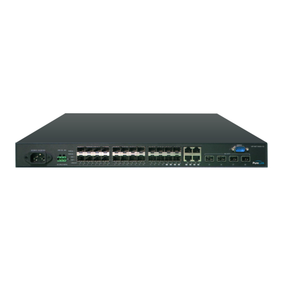
Front/Rear Panel Figure 1: VIP-NET-0424-1G Front Panel Figure 2: VIP-NET-0424-1G Rear Panel LED Descriptions The LEDs on the rear panel provide users with switch status checking and monitoring. There are two types of LEDs as follows: AC/DC Power LED • Indicates if the switch is powered up correctly or not. System LED • Indicates if the system is ready or not. Alarm LED • Indicates if the system is normal or not. Port Status LEDs • Indicates the current status of each port. Users can check these LEDs to understand the port status. VIP-NET-0424-1G QUICK START GUIDE VERSION 1.1... - Page 9 State Description An abnormal state, such as temperature, voltage or Alarm Red Off The system is normal. fan .speed, has been detected in the switch. Port Status LEDs LED Color State Description The port is enabled and established a link to connected Green device, and the connection speed is 1000Mbps. Blinking The port is transmitting/receiving packets, and the Green connection speed is 1000Mbps. The port is enabled and established a link to connected Amber On RJ45 Ports device, and the connection speed is 10/100Mbps. Amber Blinking The port is transmitting/receiving packets, and the connection speed is 10/100Mbps. The port has no active network cable connected, or it is Off not established a link to connected device. Otherwise, the port may have been disabled through the switch user interface. VIP-NET-0424-1G QUICK START GUIDE VERSION 1.1...
- Page 10 The port is enabled and established a link to connected Amber On device, and the connection speed is 100Mbps. SFP Ports Amber Blinking The port is transmitting/receiving packets, and the connection speed is 100Mbps. The port has no active network cable connected, or it is not established a link to connected device. Otherwise, Off the port may have been disabled through the switch user interface. The port is enabled and established a link to connected Blue device, and the connection speed is 10Gbps. Blinking The port is transmitting/receiving packets, and the Blue connection speed is 10Gbps. The port is enabled and established a link to connected Green SFP+ Ports device, and the connection speed is 1Gbps. Blinking The port is transmitting/receiving packets, and the Green connection speed is 1Gbps. The port has no active network cable connected, or it is Off not established a link to connected device. Otherwise, the port may have been disabled through the switch user interface. VIP-NET-0424-1G QUICK START GUIDE VERSION 1.1...
-
Page 11: Reset Button
Reset Button By pressing and holding the Reset button, users can perform the following tasks. Reset the Switch • To reboot and get the switch back to the previous configuration settings saved. Restore the Switch to Factory Defaults • To restore the original factory default settings back to the switch. NOTE: According to the table below, users can easily judge which task is being performed while pressing the Reset button by reading the LED behavior. Once the LED behaviors are correctly displayed, users may simply release the button. Reset Button Descriptions Port Status LED Task to be Performed Press & Hold Duration SYS LED Behavior Behavior Reset the Switch 2 ~ 7 seconds Blinking, Green ALL LEDs Light OFF Restore to Defaults 7 ~ 12 seconds Blinking, Green ALL LEDs Stay ON VIP-NET-0424-1G QUICK START GUIDE VERSION 1.1... -
Page 12: Installation
INSTALLATION Package Contents (1) VIP-NET-0424-1G Media Hub • (1) AC power cord • (1) Terminal Block • (4) Adhesive rubber feet • NOTE: This network switch is for indoor use. To use with outdoor devices such as outdoor (surveillance) cameras or outdoor Wi-Fi APs, installation of a surge protector or surge suppressor is highly recommended in order to protect the switch. 19” Rack Installation STEP 1: Attach the mounting brackets to both sides of the chassis. Insert screws and tighten then with a screwdriver to secure the brackets. Figure 3: Attaching brackets to the switch VIP-NET-0424-1G QUICK START GUIDE VERSION 1.1... -
Page 13: Desk Or Shelf Mounting
STEP 2: Place the switch on a rack shelf in the rack. Push it in until the oval holes in the brackets align with the mounting holes in the rack posts. STEP 3: A ttach the brackets to the posts. Insert screws and tighten them. Figure 4: Attaching brackets to the rack post Desk or Shelf Mounting Step 1: Verify that the workbench is sturdy and reliably grounded. Step 2: Attach the four adhesive rubber feet to the bottom of the switch. Figure 5: Attaching the rubber feet VIP-NET-0424-1G QUICK START GUIDE VERSION 1.1... -
Page 14: Connecting The Ac Power Cord
Connecting the AC Power Cord Step 1: Connect the AC power cord to the AC power receptacle of switch. Step 2: Connect the other end of the AC power cord to the AC power outlet. Step 3: Check the SYS LED. If it is ON, the power connection is correct. Figure 6: Connecting the AC power cord Connecting the DC Power Cord Step 1: Insert the negative/positive DC wires into the V-/V+ terminals, respectively. Step 2: To keep the DC wires from pulling loose, use a small flat-blade screwdriver to tighten the wire-clamp screws on the front of the terminal block connector. Step 3: Insert the terminal block connector prongs into the terminal block receptor. Step 4: Check the SYS LED. If it is ON, the power Figure 7: Connecting the DC power cord connection is correct. VIP-NET-0424-1G QUICK START GUIDE VERSION 1.1... -
Page 15: Installing Sfp/Sfp+ Modules
Installing SFP/SFP+ Modules You can install or remove a mini-GBIC SFP/SFP+ module from a SFP/SFP+ port without having to power off the switch. Step 1: Insert the module into the SFP/SFP+ port. Step 2: Press firmly to ensure that the module seats into the connector. Figure 8: Installing an SFP/SFP+ module NOTE: The SFP/SFP+ ports should use UL listed optional transceiver product - rated 3.3Vdc, Class 1 laser. VIP-NET-0424-1G QUICK START GUIDE VERSION 1.1... -
Page 16: Initial Configuration
192.168.1.250), then you can access the Web interface of the switch using the switch’s default IP address as shown below. NOTE: The factory default IP address of the switch is 169.254.1.10 The factory default Subnet Mask of the switch is 255.255.255.0 Initial Switch Configuration Procedure The initial switch configuration procedure is as follows: Turn on the PC that you will use for the initial configuration. Please make sure the PC has an Ethernet RJ45 connector. Reconfigure the PC’s IP address and Subnet Mask as below, so that it can communicate with the switch. The method to change the PC’s IP address, for example, for a PC running Windows® 7/8.x/10, is as follows: Step 1: Type “network and sharing“ into the Search box in the Start Menu Step 2: Select Network and Sharing Center Step 3: Click on Change adapter settings on the left of PC screen NOTE: Users can also skip step 1 to 3, by pressing WinKey+R and type ”ncpa.cpl” command to get to step 4 directly. Step 4: Right-click on your local adapter and select Properties Step 5: In the Local Area Connection Properties window highlight Internet Protocol Version 4 (TCP/IPv4) then click the Properties button. NOTE: Be sure to record all your PC’s current IP settings to be able to restore them later. Step 6: Select the radio button Use the following IP address and enter in the IP for the PC (e.g. any IP address not in use, and in between 192.168.1.2 and 192.168.1.254), Subnet mask (e.g. 255.255.255.0), and Default gateway that corresponds with your network setup. Then enter your Preferred and Alternate DNS server addresses. Step 7: Click OK to change the IP address of the PC. Power on the switch to be initially configured, and wait until it has finished its start-up processes. Connect the PC to any port on the switch using a standard Ethernet cable, and check the port LED on the switch to make sure the link status of the PC’s is OK. VIP-NET-0424-1G QUICK START GUIDE VERSION 1.1... - Page 17 Run your Web browser on the PC and enter the factory default IP address, so as to access the switch’s Web interface. If your PC is configured correctly, you will see the login page of the switch as shown in Figure 9 below. Figure 9: Web Interface login page If you do not see the above login page, please perform the following steps: Refresh the web page. • Check to see if there is an IP conflict issue. • Clean browser cookies and temporary internet files. • Check your PC settings again and repeat step 2. • Enter the factory default username and password in login page. Click “Login” to log into the switch. NOTE: The factory default Username of the switch is admin. There is no factory default Password of the switch. VIP-NET-0424-1G QUICK START GUIDE VERSION 1.1...
-
Page 18: Troubleshooting
TROUBLESHOOTING The following table provides information for users to easily troubleshoot problems by taking actions based on the suggested solutions within. Symptoms Possible Causes Suggested Solutions 1. Check if correct power cord is connected firmly to the switch and to the AC/DC outlet socket. 2. Perform power cycling the switch by unplugging and The switch is not SYSTEM LED is Off plugging the power cord back into the switch. receiving power. 3. If the LED is still off, try to plug power cord into different AC/DC outlet socket to make sure correct AC/DC source is supplied. 1. Check if the cable connector plug is firmly inserted and locked into the port at both the switch and the connected device. 2. Make sure the connected device is up and running The port is not correctly. Port Status LED is connected or the Off connection is not 3. If the symptom still exists, try different cable or different working. port, in order to identify if it is related to the cable or specific port. 4. Check if the port is disabled in the configuration settings via WEB user interface. VIP-NET-0424-1G QUICK START GUIDE VERSION 1.1... -
Page 19: Glossary
HTTP Live Streaming, found with browsers such as Chrome, Firefox, and Safari GOP Group of Pictures – terminology used when encoding MPEG video Bitrate quantity of bits per second sent from the encoder, in kilobits Encoded Size Horizontal and vertical pixel counts of output image resolution H.264 high quality, low bitrate motion-compensation based compression standard Bitrate Control refers to VBR (Variable Bit Rate), or CBR (Constant Bit Rate) CBR Constant Bit Rate, used to save file size when content has similar motion throughout VBR Variable Bit Rate, used vary bit rate dependent on content changes and provides most favorable results. Transport Stream, commonly used for audio/video streaming based on MPEG-2 RTSP Real Time Streaming Protocol for request communications between media servers and clients Multicast IP IP address for data (audio/video) broadcasting. An audio/video encoder such as the VIP-NET-0424-1G will have both a device IP address (192.168.1.168) and a multicast IP address for broadcasting the audio/video stream (e.g.: 238.0.0.1:1234) RTMP Real Time Messaging Protocol, a TCP based streaming protocol with persistent connectivity AAC Audio coding standard used by YouTube, Apple, Sony, etc. ONVIF Open Network Video Interface Forum, a standardization of IP based security products G711A A PCM audio companding standard used in telephony VIP-NET-0424-1G QUICK START GUIDE VERSION 1.1... -
Page 20: Warranty & Customer Service
Any implied warranties that may be imposed by law are limited to the terms of this limited warranty. This warranty statement supersedes all previous warranties. WARRANTY RETURNS/REPAIRS/EXCHANGES No merchandise may be returned without prior authorization from PureLink, and a Return Materials Authorization (RMA) number. Failure to comply with these conditions will result in rejection of the returned merchandise. Any warranty service on Products must be arranged through Dealer. Authorized returns must be shipped freight prepaid and fully insured to PureLink, Ramsey, NJ USA, with the RMA number clearly marked on the outside of all shipping boxes and containers. PureLink reserves the right at its sole discretion to refuse any shipments arriving freight collect or without an RMA number. Any authorized returned merchandise must be accompanied by a note describing the reason for return, along with contact information including name, phone number, return mailing and shipping addresses, e-mail address, and RMA number. - Page 21 Most problems can be corrected over the phone through close cooperation between Customer and a PureLink technician. To better enable PureLink to address a warranty claim, please have the Product’s serial and model numbers. If PureLink, in its sole discretion, determines that an on-site visit or other remedial action is necessary, PureLink may send a representative to Customer’s site.
Need help?
Do you have a question about the VIP-NET-0424-1G and is the answer not in the manual?
Questions and answers