Table of Contents
Advertisement
Quick Links
Advertisement
Table of Contents

Related Manuals for SIIG AV-GM0413-S1


Summary of Contents for SIIG AV-GM0413-S1
- Page 1 DVI Extender over Dual Cat.X with RS-232 P/N: AV-GM0413-S1...
-
Page 2: Table Of Contents
However, like all electronic equipments, the AV-GM0413-S1 should be used with care. Please read and follow the safety instructions to protect yourself from possible injury and to minimize the risk of damage to the unit. -
Page 3: Introduction
AV-GM0413-S1 makes your digital signage application with the upmost performance in pure digital domain. The AV-GM0413-S1 includes two units: transmitting and receiving units. The transmitting unit is connected to your PC DVI output and serial port, such as COM1, and the receiving unit is connected to the monitor with serial control such as touch panels. -
Page 4: Specifications
SPECIFICATIONS Model Name AV-GM0413-S1 Technical AV-GM0413-S1-TX AV-GM0413-S1-RX Role of usage Transmitter [TX] Receiver [RX] HDMI compliance DVI 1.1 HDCP compliance Single-link 165MHz [4.95Gbps] Video bandwidth Up to WUXGA [1920x1200@60Hz] & UXGA [1600x1200@60Hz] 1920x1200@60Hz – 30m [100ft] Video support 1024x768@60Hz – 60m [200ft]... -
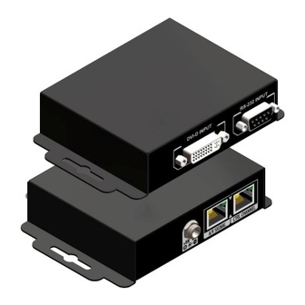
Page 5: Panel Descriptions
A/V SIGNAL: Plug in a Cat-5/5e/6 cable that needs to be linked to the A/V SIGNAL port of the receiving unit AV-GM0413-S1-RX. CTRL CHANNEL: Plug in a Cat-5/5e/6 cable that needs to be linked to the CTRL CHANNEL port of the receiving unit AV-GM0413-S1-RX. Receiving unit ► AV-GM0413-S1-RX Front Panel Rear Panel Signal Level: Adjust the 8-level equalization control to the received HDMI signals. - Page 6 RS-232 OUTPUT: Connect to a RS-232 enable device or Touch panel with serial port control +5V DC: Connect to 5V DC power supply. A/V SIGNAL: Plug in a Cat-5/5e/6 cable that needs to be linked to the RJ45 connector of the transmitter.
-
Page 7: Hardware Installation
HARDWARE INSTALLATION 1. Connect the transmitter to your DVI source (PC). 2. Connect the transmitter to your serial controlled device. 3. Connect the receiver to the remote DVI monitor. 4. Connect the receiver to the serial control device or monitor. 5. -
Page 8: Notice
NOTICE 1. If the DVI or HDMI device requires the EDID information, please use EDID Reader/Writer to retrieve and provide DVI/HDMI EDID information. 2. All HDMI over CAT5 transmission distances are measured using Belden 1583A CAT5e 125MHz LAN cable and ASTRODESIGN Video Signal Generator VG-859C. 3. -
Page 9: Warranty
The SELLER will NOT be liable for direct, indirect, incidental, special, or consequential damages resulting from any defect or omission in this manual, even if advised of the possibility of such damages. Also, the technical information contained herein regarding the AV-GM0413-S1 features and specifications is subject to change without further notice.
Need help?
Do you have a question about the AV-GM0413-S1 and is the answer not in the manual?
Questions and answers