
Related Manuals for Thermo Scientific 314


Summary of Contents for Thermo Scientific 314
- Page 1 Lab-Line Air-Jacketed Compact Automatic CO Incubators Model No. 314-1CE LT1447X1 • 4/11/07...
-
Page 2: Table Of Contents
Unpacking and Installation ............................6 Shipping Carton ..............................6 Location ................................6 Electrical Requirements ............................6 Humidification, 314 Series Automatic CO2 Incubators ..................7 Gas Filter Interface Assembly Kit ..........................7 Installation Procedure ............................7 Figure A: Back of Unit - Rear Panel View, Exterior ....................8 Description and Features ............................10 Basic Components ..............................10... -
Page 3: Safety Information
Safety Information Your Thermo Scientific Lab-Line Air-Jacketed Compact Alert Signals Automatic CO2 Incubator has been designed with func- tion, reliability, and safety in mind. It is your responsibility to install it in conformance with local electrical codes. It is Warning... -
Page 4: Specifications
Specifications Electrical Requirements 314: 120 Volts, 50/60 Hz, 200 Watts, 1.7 Amps 314-1CE: 230 Volts, 50/60 Hz, 200 Watts, 0.8 Amps Temperature Range Ambient +5°C to 60°C Temperature Control ±0.1°C at 37°C Uniformity in Chamber Within the chamber, ±0.25°C Algorithm... -
Page 5: Declaration Of Conformity
PECIFICATIONS Declaration of Conformity (for 220-240 volt, -33 CE models only) We hereby declare under our sole responsibility that this product conforms with the technical requirements of the following standards: EMC: EN 61000-3-2 Limits for harmonic current emissions EN 61000-3-3 Limits for voltage fluctuations and flicker EN 61326-1 Electrical equipment for measurement, control, and... -
Page 6: Unpacking And Installation
Unpacking and Installation Shipping Carton The shipping carton should be inspected upon delivery. When received, carefully examine for any shipping dam- age before unpacking. If damage is discovered, the deliv- ering carrier should both specify and sign for the damage on your copy of the delivery receipt. -
Page 7: Humidification, 314 Series Automatic Co2 Incubators
Gas Filter Interface Assembly Kit Models 314 and 314-1CE require this assembly to be used for both CO2 and air. Kit includes: • (4) Hose Clamps - #250-331-00 •... - Page 8 NPACKING AND NSTALLATION Figure A: Back of Unit – Rear Panel View, Exterior Back of unit In-line filter Hose clamp Hose clamp 1/4” (0.64 cm) ID tubing Hose clamp 1/4” (0.64 cm) hose barb connections (CO2 fitting) Pressure regulators and gauges must be installed on each tank.
- Page 9 NPACKING AND NSTALLATION Standard Type (Correct) Siphon Type (Incorrect) Compressed Gas Association #320 Warning tag indicating that cylinder is siphoning type. connector. Aluminum ring. Gas head space. Gold band. Liquid CO2 filled to 68% equal weight of water that cylinder would hold at Stamp or marking on cylinder: "Siphon"...
-
Page 10: Description And Features
Description and Features 9 10 11 12 1. Control panel 2. CO2 sensor 3. CO2 inlet port 4. Temperature sensor 5. Chamber gasket 6. Chamber shelves 7. Sample port inlet 8. Leveling feet 9. Inner glass door, handle shaft 10. Inner glass door 11. - Page 11 ESCRIPTION AND EATURES Chamber Ceiling, Interior Circulating Fan Rear Panel View, Exterior Gas Inlet Port Cordset Circuit Breaker(s) RS232 Data Pins Connector Power Switch...
-
Page 12: Description
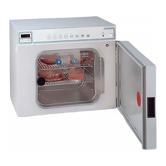
A double-door system has a tempered glass inner door that provides unobstructed viewing of the entire chamber. 314 series chambers are constructed of seamless stainless steel for cleaning ease and maintenance; 2 stainless steel shelves are standard—a total capacity is 5 shelves. -
Page 13: Features
Control Panel 314 series control panels have a series of command keys that enable users to enter set point values for tempera- ture, carbon dioxide, door heat and to calibrate a unit as required. - Page 14 ESCRIPTION AND EATURES CAL COMMAND KEY: The CAL key permits cal- ibration of temperature and CO2 when in this command mode. The Up and Down arrow keys are used to change the readout to correspond with the readings obtained from known stan- dards of temperature or CO2 measurement.
- Page 15 ESCRIPTION AND EATURES steps to correct the problem. Note that indicat- ing light continues to flash. If problem is not cor- rected, the alarm will resume after one hour has Note passed. Decreases in temperature and CO2 due to normal door openings are tol- •...
-
Page 16: Proper Sequencing Important In Operating Command Keys
ESCRIPTION AND EATURES 12. SAMPLE PORT: This access port is available for sampling the atmosphere in the chamber when executing calibration procedure such as might be done using a Fyrite or other CO2 analysis procedure. Proper Sequencing Important in Operating Command Keys To enter commands correctly, it is important to press the keys in SEQUENCE. -
Page 17: Alarms
ESCRIPTION AND EATURES Alarms POWER OUTAGE: In the event of a power outage, the LED display will flash to alert the user to take corrective action. If the power outage is of a temporary nature, pressing any key will restore unit to operating status. Everything operates normally after a power outage. -
Page 18: Additional Features
ESCRIPTION AND EATURES Additional Features • CO2 sensor (on thermal-conductivity units only). • Mechanically convected airflow. • 1.2 cubic feet, 304-stainless steel chamber; full- view heated glass door • 2 shelves... -
Page 19: Operation
Operation Startup and Operation Connect unit to power supply meeting the require- ments as noted on the nameplate. Turn the power switch ON. Press the SET key first and then the parameter— CO2, TEMP, DOOR HEAT—which is to be adjusted. Use the UP and DOWN arrow keys to enter the desired value. -
Page 20: Setting Operating Temperature And High Limit Setpoint
PERATION Once your password is entered, wait 5 seconds and the unit will store this value in its nonvolatile memory. REMEMBER TO NOTE THE PASS- WORD IN A PLACE FOR SAFEKEEPING AND ACCESSIBLE TO YOURSELF OR A COL- LEAGUE. Subsequent access is denied unless the correct password is entered. -
Page 21: Condensation On Inner Glass Door
PERATION After sufficient time has elapsed, rotate the high limit thermostat counterclockwise while watching the red lamp. When the lamp is lit, you have adjusted the high limit set point to be equal to the operating set point. Now rotate the high limit thermostat clockwise 30º... -
Page 22: Temperature Calibration
PERATION Correct setting of the door heat control depends on varying factors such as chamber tempera- ture. In general, the setting should produce the minimal amount of heat necessary to eliminate glass door condensation and no more. If unsure of the amount of heat to produce, start at a low value and increment the setting by 5% every couple of hours until condensation is eliminated. - Page 23 PERATION All internal CO2 parameters automatically track this change: FOR OPTIMUM OPERATION OF YOUR INCU- BATOR, CHECK CO2 WITH FYRITE OR OTHER CO2 ANALYZER WEEKLY.
-
Page 24: Using Fyrite
Using Fyrite Hints on Using the Fyrite The following information is intended to supplement that Note found in the Fyrite manual and is based on experience A little water goes a long way. Use working with users of our Incubators. only a couple drops of distilled water at once. -
Page 25: Taking A Fyrite Reading
SING YRITE water will transfer into the Fyrite causing the fluid level to rise. Repeat this procedure until the fluid level reads correctly. • Inspect the Fyrite filter in the clear plastic casing between the hoses for any contamination or growth. - Page 26 SING YRITE CO2, so that it is important to let most of the smaller bubbles surface. Turn it right side up and hold it at 45 degrees. Allow the fluid to fill the Fyrite and depress the plunger again. This clears the Fyrite of any CO2 that might cause a false reading.
- Page 27 SING YRITE 11. Once the bulb has been pumped the required number of times, HOLD THE SQUEEZE BULB IN THE "SQUEEZED" POSITION and release the pressure on the cup that will also release the plunger. This traps the sample from the Incubator in the Fyrite chamber and allows the fluid to absorb the CO2.
-
Page 28: Maintenance
Maintenance Cleaning Warning Every 6 months inspect the chamber. Clean the stainless Disconnect from the power supply steel interior with any good scale remover or dilute acetic acid prior to maintenance and servicing. and a synthetic scouring pad. DO NOT USE chlorine-based cleansers or bleach, scouring pads with metallic content, or harsh abrasives to clean any part of the Incubator. -
Page 29: The Ph Factor
AINTENANCE ed soft tap water provided the total solids concentration is < 500 PPM. We do NOT recommend using 18 meg-ohm deionized water. If this is the only source of treated water available, mix with regular tap water at a 50/50 ratio. The pH Factor Check pH regularly. -
Page 30: Cleansing Agents
AINTENANCE Cleansing Agents Anti-fungal and anti-bacterial additives are permissible to use as long as the pH of the aqueous solution is kept within the range of 7 to 9. These are available through laboratory distributors. Be sure to CONFIRM that they are not harmful to stainless steel. -
Page 31: Materials Effective In Disinfecting
AINTENANCE • Oxalic acid 2% to 5% in warm water. Swab solution on surface allowing it to remain until rust is loosened. Immediately follow with a clean water rinse. This method should ONLY be used if SEVERE rust and scale stains are present. Regardless of the approach utilized, ALWAYS follow the manufacturer’s directions and allow the chemicals to do the cleaning with MINIMAL scrubbing. -
Page 32: Replacement Parts
Replacement Parts 314 SERIES AUTOMATIC CO2 INCUBATORS: DESCRIPTION PART NUMBER Printed Circuit Board Assy: 018-478-00 CO2 Sensor Assy: TD1447X1 Axial Fan: FA1447X1 Solenoid Noise Suppressor: CA1447X4 Circuit Breaker, 5-Amp: 330-118-00 Line Filter: 330-347-00 Fuse, 0.3Amp: 330-404-00 Chamber Heater, 120V: EL1447X4... -
Page 33: Ordering Procedures
Ordering Procedures Please refer to the Specification Plate for the complete model number, serial number, and series number when requesting service, replacement parts or in any corre- spondence concerning this unit. All parts listed herein may be ordered from the Thermo Scientific dealer from whom you purchased this unit or can be obtained promptly from the factory. -
Page 34: Decontamination Statement
Decontamination Statement We cannot accept any product or component sent to the fac- tory for repair or credit that is contaminated with or has been exposed to potentially infectious agents or radioactive materi- als. No product or component will be accepted without a "Return Goods Authorization"... -
Page 36: Two Year Limited Warranty
(ii) misuse (including use inconsistent with written operating instructions for the product), mishandling, contamination, overheating, modification or alteration of the product by any customer or third party or (iii) use of replacement parts that are obtained from a party who is not an authorized dealer of Thermo Scientific prod- ucts.
Need help?
Do you have a question about the 314 and is the answer not in the manual?
Questions and answers