Table of Contents
Advertisement
Operating Instructions
Dulcodes M
UV-System
Please affix device label here!
Please read the operating instructions through completely before commissioning this equipment! Do not discard!
Any part which has been subject to misuse is excluded from the warranty!
Part No. 987340
ProMinent Dosiertechnik GmbH
69123 Heidelberg
Germany
BA DS 007 07/05 GB
•
•
Advertisement
Table of Contents

Related Manuals for ProMinent Dulcodes M


Summary of Contents for ProMinent Dulcodes M
- Page 1 Operating Instructions Dulcodes M UV-System Please affix device label here! Please read the operating instructions through completely before commissioning this equipment! Do not discard! Any part which has been subject to misuse is excluded from the warranty! Part No. 987340...
-
Page 2: Notes For The User
Ignoring safety information can result in damage to machinery or other materials. NOTE Special guidelines. Publishing details: Operating Instructions Dulcodes M UV-System © ProMinent Dosiertechnik GmbH, 2001 Address: ProMinent Dosiertechnik GmbH Im Schuhmachergewann 5-11 69123 Heidelberg · Germany info@prominent.com www.prominent.com Subject to technical alterations. -
Page 3: Table Of Contents
5.2.2 Electrical Connections ..........................5.2.3 Attaching the Temperature Sensor ....................5.2.4 Positioning and Connecting the Limit Switches ..............5.2.5 Connecting the UV Sensor ........................5.2.6 Attaching the Wiper Motor ........................5.2.7 Installing the Terminal Box ........................® Page 3 ProMinent... - Page 4 7.3.1 Calibrating the Sensor ..........................Wiper Maintenance ..............................Replacing the Fan Filter Mats and Air Exit Filter ................. 8 Troubleshooting ..................................Appendix Operation Log ....................................EC Declaration of Conformity ............................Data sheet ......................................Spare parts list ....................................Page 4 ® ProMinent...
-
Page 5: Application
UV radiation breaks down the harmful substances in swimming pool water effectively and reliably kills bacteria that even chlorine struggles to eradicate. Dulcodes M UV systems are supplied ready for connection. There are various models to choose from and each one has a specific identity code. -
Page 6: Function
(Only for maintenance: An attempt to ignite the lamp can be made during the cooling period by pressing the enter key). NOTE The radiation chamber cannot be emptied in order to carry out maintenance until the cooling period has elapsed. Page 6 ® ProMinent... -
Page 7: Controller
This should be given in the event of a query or complaint. Default setting The controller system of the Dulcodes M UV system is preset at the factory. Unless calibrating the sensor, it is not usually necessary to change the settings. NOTE The settings can only be changed if the UV system has been switched off. -
Page 8: Function Keys
NOTE • Keep the START/STOP key depressed for at least 2 seconds each time. • If none of the keys are pressed for 5 minutes, the display returns to the normal operating status display automatically. Page 8 ® ProMinent... -
Page 9: Operating Status Display And Parameter Setting
Time x:xx m Safety threshold xx % -xx [%] Safety threshold below setpoint Warning threshold xx % -xx [%] Warning threshold below setpoint Returns to trend display automatically Jumps to programming mode Jumps to “Change Access code” mode ® Page 9 ProMinent... - Page 10 Turn-ons xx min Lamp hours Start rinse duration xx h Lamp turn-ons x min only for equipment with a conventional ballast Control Control Control Control External Control control XmA = yy% 20 mA = zzz% manual Page 10 ® ProMinent...
-
Page 11: Trend Display
The warning and safety threshold is not indicated NOTE A full vertical line is shown in the trend display for each calibration of the UVC sensor. Default setting Time window 100 days Maximum sensor signal value 120 % ® Page 11 ProMinent... -
Page 12: Starting A Wiper Cycle
Access code” NOTE Make a note of the access code. The correct access code must be entered before parameters can be set. The default access code does not guarantee protection against unauthorized changes. Default setting 5000 Page 12 ® ProMinent... -
Page 13: Setting The Language
This results in the system independently adjusting variable operating conditions, such as radiator weathering, fluctuations in water quality, etc. NOTE The control of radiation output should only take place in an area designated for electrical control gear. Default value 100 % ® Page 13 ProMinent... -
Page 14: Sensor Signal System
An indicator can be connected to the SAFETY THRESHOLD relay of the control system. The relay closes when the signal falls below the safety threshold. Default setting The safety threshold is normally set at 50 % but it can be changed for special applications. Page 14 ® ProMinent... -
Page 15: Setting The Warning Threshold In Operating Mode "Control On
The warning threshold is normally set at 5 percentage points -5 [%] below the reference value (operating mode “control on”). E.g.: with a reference value of 60 % and a warning threshold of -5 [%] the system will issue a warning if a probe signal falls to 55 %. ® Page 15 ProMinent... -
Page 16: Setting The Wiper Interval
If the maximum water temperature does not fall by approximately 5 °C during the maximum flushing period (please refer to 4.3.14) and/or the water temperature increases to the maximum level, the control system switches off the lamp and reports a fault. Page 16 ® ProMinent... -
Page 17: Maximum Rinse Duration Following A Temperature Rise
When the water quality improves, the UV disinfection system returns to normal operation. If the UVC sensor signal does not rise above the safety threshold during the maximum free rinse duration, the UV disinfection system reports a fault. Default setting 1 minute ® Page 17 ProMinent... -
Page 18: Activating Lamp Post-Burn
4.3.20 Displaying/Resetting the Counters Operating hours Lamp hours 400 h 400 h Turn-ons Lamp turn-ons The OPERATING HOURS and TURN-ONS counters cannot be reset. The LAMP HOURS and LAMP TURN-ONS counters can be reset. Page 18 ® ProMinent... -
Page 19: Switching The Control On/Off
UV disinfection system can no longer be operated. IMPORTANT Remove the jumper when connecting a fault indicator. If you do not, faults will not be reported. ® Page 19 ProMinent... -
Page 20: Assembly And Installation
Screw auxiliary fitting into the radiation chamber on the side of the motor, if this has not already been done. • Insert the auxiliary assembly tube (PVC tube) into the radiation chamber from the lid end and clamp it gently in the assembly aid. Page 20 ® ProMinent... - Page 21 Assembly and Installation ® Page 21 ProMinent...
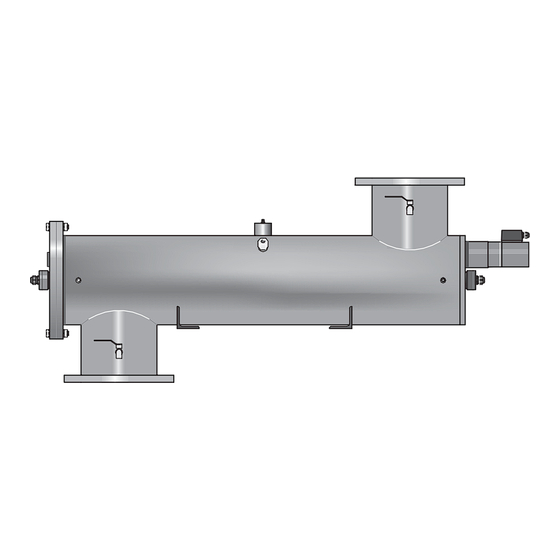
- Page 22 (only in systems with conventional ballast) Bleed valve Safety shield UV sensor Motor support Bleed valve Assembly support Plastic screw Locking nut Support stirrup Temperature sensor UV sensor O-ring Support panel Spindle nut Wiper Limit switch Base Page 22 ® ProMinent...
-
Page 23: Assembly
NOTE To prevent water from dripping into the end of the cable conduit, if necessary, provide appropriate protection for the end of the conduit and/or install it so that the opening is facing downwards. ® Page 23 ProMinent... -
Page 24: Electrical Connections
Connect the limit switches to the right angle plugs. Please note the designation of the cables and threaded pipe sockets. IMPORTANT If the limit switch connections are confused the wiper motor will not recognize the end positions. This will cause wiper failure. Page 24 ® ProMinent... -
Page 25: Connecting The Uv Sensor
Push the clamp over the protection tube on the motor side and screw it into the radiation chamber; tighten it by hand. Use the hook spanner to tighten the tube clamp on both sides. Only a small amount of force is required. ® Page 25 ProMinent... -
Page 26: Installing And Connecting The Lamp
Pull the safety shield (split tube made of transparent plastic) apart at the split carefully and push it down over the motor supports. The safety shield must be flush against the radiation chamber. The hole in the safety shield is for the protection tube clamp. Page 26 ® ProMinent... -
Page 27: Commissioning
Calibrate the UVC sensor to 100 % within the commissioning period as described in section 6.3. It is not necessary to wait for a stable sensor value. NOTE Please follow the separate operating instructions enclosed for special applications that require the sensor signal to be displayed in W/m ® Page 27 ProMinent... -
Page 28: Calibrating The Uvc Sensor
Please follow the separate operating instructions enclosed for special applications that require the sensor signal to be displayed in W/m . All new UV lamps need a run-in period of 100-200 hours. Therefore, the UVC sensor should be recalibrated approximately 200 hours after commissioning. Page 28 ® ProMinent... -
Page 29: Setting The Radiation Output In Operating Mode "Control Off
Press the CHANGE button to go to the CONTROL display. Confirm by pressing ENTER, REQUEST RELEASE CODE appears. Enter the release code and confirm by pressing ENTER; CONTROL re-appears; the setting to be adjusted now flashes. ® Page 29 ProMinent... - Page 30 20mA signal needs to allocated maximum permitted flow rate for the Dulcodes M according to the data sheet depending on UV transmission and required dose of radiation Press the CHANGE button to go to the CONTROL display.
-
Page 31: Maintenance
Keep a log of all maintenance work carried out. There is a template for this in the appendix. NOTE The X ring for sealing the wiper drive spindle must be changed at least once every two years. Any slight leakage which may occur beforehand (slight dripping) will not impair system performance. ® Page 31 ProMinent... -
Page 32: Replacing The Lamp
Remove the lamp cover carefully until the connection terminal is exposed. If necessary, hold the spacer (glass tube) with one hand. Loosen the lamp cable on the connection terminal and remove the lamp cover with the lamp connection cable. Remove the spacer. Remove the lamp. Page 32 ® ProMinent... -
Page 33: Cleaning The Lamp Protection Tube
For most applications, it is sufficient to clean the protective tube when the lamp is replaced. Acids such as dilute phosphoric acid, citric acid or dilute nitric acid are particularly suitable cleaning agents. ® Page 33 ProMinent... - Page 34 Clean the UV sensor as described in section 7.3. Finally, install the UV lamp and fill and bleed the radiation chamber (see section 7.1). NOTE Comply with current guidelines and regulations when disposing of the cleaning solution. Page 34 ® ProMinent...
-
Page 35: Cleaning The Uvc Sensor
2 years. After 4 years, the entire wiper mechanism should be replaced. IMPORTANT • The drive spindle may be damaged if the drive nut is damaged or worn. • The drive spindle may be damaged if the friction bearing is damaged or worn. ® Page 35 ProMinent... -
Page 36: Replacing The Fan Filter Mats And Air Exit Filter
The UV transmission of the water to be disinfected has deteriorated. Remedy Improve the water quality Possible cause The UV lamp is at the end of its useful life. Remedy Insert a new UV lamp Possible cause Sensor not calibrated. Remedy Calibrate the sensor Page 36 ® ProMinent... - Page 37 Press the ENTER key to acknowledge the fault message Water temperature to high Possible cause Inadequate water flow. Remedy Increase water flow Possible cause Flushing valve does not open. Remedy Replace flushing valve Possible cause Flushing valve too small. Remedy Replace flushing valve ® Page 37 ProMinent...
- Page 38 Possible cause Supply voltage too low on one or more of the ballasts. Remedy Check supply voltage and fine-wire fuse in the ballast (skilled electricians only) Possible cause Faulty ballast. Remedy Replace ballast (skilled electricians only) Page 38 ® ProMinent...
- Page 39 Replace the control system (skilled electricians only) Fault indication: signal < 4 mA Störung Signal < 4 mA Cause Input signal in external control setting 4-20 mA is < 4 mA Remedy check signal cable, check control signal ® Page 39 ProMinent...
-
Page 40: Operation Log
Operation Log Page 40 ® ProMinent... -
Page 41: Ec Declaration Of Conformity
EC Declaration of Conformity ® Page 41 ProMinent... -
Page 42: Data Sheet
40 °C • maximum operating pressure: 10 bar*) • no corrosive or abrasive properties, chloride content < 250 ppm • not liable to sediments *) lower operating pressures are possible for specially designed systems! Page 42 ® ProMinent... -
Page 43: Spare Parts List
2 years 901 Magnet 1009654 as required 904 Stop position switch 1009357 as required Spanner for d68-75 with pivot d6 1009515 as required Sealing cement Neofermit 553004 as required Tap grease OKS 477 791681 as required ® Page 43 ProMinent... - Page 44 Spare parts list Page 44 ® ProMinent...
- Page 45 Spare parts list ® Page 45 ProMinent...
- Page 46 Spare parts list Page 46 ® ProMinent...
- Page 47 Spare parts list ® Page 47 ProMinent...
Need help?
Do you have a question about the Dulcodes M and is the answer not in the manual?
Questions and answers