
Related Manuals for Festo HSP AE Series


Summary of Contents for Festo HSP AE Series
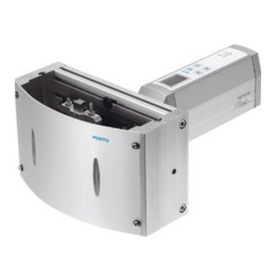
- Page 1 Handling module HSP−...−AE Manual Type HSP− −AE−IO− Manual 541 946 en 0510NH [691 172]...
- Page 2 ® ® Adobe and Reader are either a registered trademark or a trademark of Adobe Systems Incorporated in the United States and/or other countries.
- Page 3 ....... . . 541 946 E (Festo AG & Co. KG, D 73726 Esslingen, Federal Republic of Germany, 2005) Internet: http://www.festo.com...
- Page 4 Contents and general instructions Festo P.BE−HSP−AE−IO−EN en 0510NH...
-
Page 5: Table Of Contents
1−15 Festo Configuration Tool (FCT) ........ - Page 6 ........4−23 Festo P.BE−HSP−AE−IO−EN en 0510NH...
- Page 7 ..........7−9 Festo P.BE−HSP−AE−IO−EN en 0510NH...
- Page 8 ............B−1 Festo P.BE−HSP−AE−IO−EN en 0510NH...
-
Page 9: Designated Use
If additional commercially−available components such as sensors and actuators are connected, the specified limits for temperatures, electrical data, pressures, torques, etc. must be observed. Festo P.BE−HSP−AE−IO−EN en 0510NH... -
Page 10: Safety Instructions
Enable the controller only if the axis system is correctly installed and parametrized. Target group This manual is intended exclusively for technicians trained in control and automation technology, who have experience in installing, commissioning, programming and diagnosing positioning systems. VIII Festo P.BE−HSP−AE−IO−EN en 0510NH... -
Page 11: Service
Contents and general instructions Service Please consult your local Festo repair service or write to the following e−mail address if you have any technical problems: service_international@festo.com Scope of delivery Included in scope of delivery: handling module and motor unit with integrated controller user documentation on CD ROM (in paper form can be ordered as accessory). -
Page 12: Important User Instructions
This means that failure to observe this instruction may result in damage to property. The following pictogram marks passages in the text which describe activities with electrostatically sensitive compo nents. Electrostatically sensitive components may be damaged if they are not handled correctly. Festo P.BE−HSP−AE−IO−EN en 0510NH... - Page 13 Accessories: Information on necessary or sensible accessories for the Festo product. Environment: Information on environment−friendly use of Festo products. Text markings The bullet indicates activities which may be carried out in · any order. 1. Figures denote activities which must be carried out in the numerical order specified.
-
Page 14: Product−Specific Terms And Abbreviations
(can be edited later via positioning set table). Input Output Input and/or output Motor unit Integrated unit consisting of the controller, encoder and motor, e.g. motor unit type MTR−DCI−... Festo P.BE−HSP−AE−IO−EN en 0510NH... - Page 15 Software end position, positive: max. limit position of the stroke in the positive direction; must not be exceeded during positioning. Software end position, negative: min. limit position in the negative direction; must be reached during positioning. XIII Festo P.BE−HSP−AE−IO−EN en 0510NH...
- Page 16 M 0 Nmm. The torque is specified either automatically in the HSP mode or if the positioning set is parametrized. Tab. 0/1: Index of terms and abbreviations Festo P.BE−HSP−AE−IO−EN en 0510NH...
-
Page 17: Manuals On The Handling Module Type Hsp
I/O interface. It also contains information on the functions of the I/O interface, as well as on commissioning with the Festo Configuration Tool" (FCT) software package. Product variants are available for coupling to field bus sys tems. -
Page 18: Information On The Version
What is new? Which FCT PlugIn? V−HM1.20 For handling modules with motor unit type V1.0.0 MTR−DCI−...−IO−HM including integrated controller and I/O interface. Supports type: HSP−12−AE−IO HSP−12−AE−IO−SD HSP−12−AE−IO−GE HSP−12−AE−IO−SD−GE HSP−16−AE−IO HSP−16−AE−IO−SD HSP−16−AE−IO−GE HSP−16−AE−IO−SD−GE HSP−25−AE−IO HSP−25−AE−IO−SD HSP−25−AE−IO−GE HSP−25−AE−IO−SD−GE Festo P.BE−HSP−AE−IO−EN en 0510NH... -
Page 19: System Summary
System summary Chapter 1 1−1 Festo P.BE−HSP−AE−IO−EN en 0510NH... - Page 20 1−15 Festo Configuration Tool (FCT) ........
- Page 21 1. System summary Handling with electric positioning motors Higher−level controller e.g. Festo type FEC... Software level: Festo Configuration Tool Motor/controller level: MTR−DCI−...−HM + coupling Drive level: handling module Fig. 1/1: Handling with electric positioning motors (principle) 1−3 Festo P.BE−HSP−AE−IO−EN en 0510NH...
-
Page 22: Design And Components
Motor position variable Type HSP−...−AE−IO−SD−...(−GE) Handling module as above, also with protective cover and side plates The SD" design is recom mended for stand−alone mode. Tab. 1/1: Designs of the handling module 1−4 Festo P.BE−HSP−AE−IO−EN en 0510NH... - Page 23 Adapters (e.g. for grippers, rotary drives). Information on ordering can be found in appendix A.4, Accessories. Instructions on fitting further accessories in conjunction with Festo components are described in the chapter Handling technology" in the system manual. 1−5 Festo P.BE−HSP−AE−IO−EN en 0510NH...
- Page 24 Cover profile for cable bearing in the grooves of the base plate or side plates Adapter kit HAPG−... (B) and in some cases additional adapter plates (C) for fastening add−on components (grippers, swivel drive) Tab. 1/2: Kits (can be ordered as accessory) 1−6 Festo P.BE−HSP−AE−IO−EN en 0510NH...
-
Page 25: Method Of Operation
2 linear guides arranged in cross−form (cross guide) 2 stops in the end positions with rubber buffers and each with a fastening rail for proximity switches 2 adjusting screws (z−stroke) Base plate with variable fitting and fastening possibilities Fig. 1/2: Structure 1−7 Festo P.BE−HSP−AE−IO−EN en 0510NH... - Page 26 The free−of−play connection between the motor unit and the drive takes place via a clamp coupling. As a further variant, a very compact motor add−on unit can be implemented with a single−stage right−angle gear unit. 1−8 Festo P.BE−HSP−AE−IO−EN en 0510NH...
- Page 27 HMI). The user interface with display and four operating buttons enables positions and the speed to be parametrized directly on the drive. via the RS232 interface (with FCT software). 1−9 Festo P.BE−HSP−AE−IO−EN en 0510NH...
- Page 28 The CI commands listed in the Object Directory can be transmitted to the motor unit with all commercially−available terminal programs. Only experienced users may use the CI commands. If necessary consult the Festo Service. HSP mode Standard sequences can be parametrized in a simplified Teach procedure (HSP mode).
- Page 29 Step mode". Relative positioning movements can also be carried out if the reference system has not yet been referenced. 1−11 Festo P.BE−HSP−AE−IO−EN en 0510NH...
- Page 30 Additonal setup position (mid−position Pos 2), e.g. as reject position for bad position (mid position Pos 2), e.g. as reject position for bad parts. Tab. 1/3: Pick and place (standard applications) 1−12 Festo P.BE−HSP−AE−IO−EN en 0510NH...
- Page 31 Teach travel for automatic parametrizing of positioning sets for typical pick and place applications (HSP mode) Positioning travel for testing a certain positioning set in the positioning set table (Move position set). 1−13 Festo P.BE−HSP−AE−IO−EN en 0510NH...
- Page 32 If an EMERGENCY STOP circuit is required for your · application, use additional separate safety limit switches (e.g. as normally−closed contacst in a series circuit) for switching off the operating voltage. 1−14 Festo P.BE−HSP−AE−IO−EN en 0510NH...
-
Page 33: Operating Elements On The Motor Unit
The visual display of the operating states is shown with 3 LEDs: Chapter 7.2 Operating voltage Power" Positioning status/bus status I/F" (= interface/field bus) Error" fault Connections The motor unit has the following connections: Chapter 3 Power supply I/O control RS232 interface to PC 1−15 Festo P.BE−HSP−AE−IO−EN en 0510NH... -
Page 34: Festo Configuration Tool (Fct)
Festo Configuration Tool (FCT) The Festo Configuration Tool (or brief FCT) is the software platform for configuring and commissioning different compo nents or devices from Festo. The FCT consists of the following components: a framework as a program starting and entry point with uniform project and data management for all supported device types. - Page 35 The FCT offers various possibilities of obtaining information or help with operation. The help for the FCT contains the complete information on operating the Festo Configuration Tool. The device−specific PlugIns each have their own help files. Printed information In order to use the complete help or parts thereof indepen dently of a PC, you can use one of the following possibilities: Use the Print"...
- Page 36 The help for the PlugIn MTR−DCI−HM" contains the complete information on operating the PlugIn. You can open the help as follows: Command [Help] [Contents of installed PlugIns] [Festo · (manufacturer name)] [MTR−DCI−HM (PlugIn name)]. Help button in the window range or dialogue of the ·...
-
Page 37: Fitting
Fitting Chapter 2 2−1 Festo P.BE−HSP−AE−IO−EN en 0510NH... -
Page 38: Turning The Motor Unit (Only Type Hsp
........2−14 2.5.3 Replacing the silencers (rubber buffers) ..... 2−17 2−2 Festo P.BE−HSP−AE−IO−EN en 0510NH... -
Page 39: Fitting
Carry out the following com missioning steps: after turning/swivelling the motor unit (type HSP−...−GE), after setting the y−stroke, after setting the z−stroke, If the load changes, take the modified work load into consideration. 2−3 Festo P.BE−HSP−AE−IO−EN en 0510NH... -
Page 40: Fitting The Handling Module
HMBN−5−M5 or with fastening kit type HMBK−ND and connecting bracket type HMBV−ND. Recommendation: Fasten the handling module preferably vertically with fasten ing kit HMBK−ND and connecting bracket HMBV−ND to one or two profile columns. 2−4 Festo P.BE−HSP−AE−IO−EN en 0510NH... - Page 41 2. Fitting Fig. 2/1: Example of fitting (accessories) Please note Note that two profile columns are required for stable fastening of the HSP−25−..2−5 Festo P.BE−HSP−AE−IO−EN en 0510NH...
- Page 42 Make sure there is sufficient space for connecting the · power cables and compressed air tubing. Avoid where possible mechanical stress of the supply · lines due to rotary and swivel movements of the handling module. 2−6 Festo P.BE−HSP−AE−IO−EN en 0510NH...
-
Page 43: Attachment Components
HSP−12 HSP−16 HSP−25 per (permitted) Dynamic torque 1.1 Nm 2.4 Nm 3.2 Nm Static toeque 5 Nm 10 Nm 15 Nm When observing the maximum work load For press−in and joining procedures without dynamic loading 2−7 Festo P.BE−HSP−AE−IO−EN en 0510NH... - Page 44 Recommendation: Use adapter kit type HAPG−..The standard hole pattern of the universal adapter forms the interface to selected Festo products, e.g. micro grippers. Mount the work load (adapter plate, rotary drive and/or gripper, gripper finger, work item) within the mounting surface of the universal adapter.
-
Page 45: Fitting The Motor Unit
Fig. 2/3: Fitting the motor unit In the case of handling modules type HSP−...−GE you can turn or swivel the motor unit. Turning the motor unit 90° ... 360° (see chapter 2.4.1) Swivelling the motor unit ±90° (see chapter 2.4.2) 2−9 Festo P.BE−HSP−AE−IO−EN en 0510NH... - Page 46 Loosen only the fastening screw of the motopr clamp. In particular, screws which are locked with sealing plugs, may not be loosened. 1. Loosen the motor clamp. 2. Screw the motor unit into the desired position. 2−10 Festo P.BE−HSP−AE−IO−EN en 0510NH...
-
Page 47: Swivelling The Motor Unit (Only Type Hsp
(see chapter 2.4.1). 2. Loosen the four fastening screws of the motor flange. 3. Swivel the drive 90° into the desired direction. 4. Tighten the four fastening screws with the specified torque (alignment on centring collar). 2−11 Festo P.BE−HSP−AE−IO−EN en 0510NH... - Page 48 3 Nm 3 Nm 6 Nm In order to carry out the functional check, swivel the · moveable mass by hand into the end positions. If necessary, correct the alignment of the motor unit. · 2−12 Festo P.BE−HSP−AE−IO−EN en 0510NH...
-
Page 49: Static Adjustment Of The Mechanical End Positions
3. Tighten the locking screw (torque 1 Nm). 4. Repeat the procedure for setting the place position. 2−13 Festo P.BE−HSP−AE−IO−EN en 0510NH... -
Page 50: Setting The Y−Stroke
One additional fastening screw of the link part (only HSP−16/25−AE−...) Do not loosen the two fastening screws of the centre piece (only HSP−16/25−AE−...) Fig. 2/7: Setting the y−stroke: Fastening screws 2−14 Festo P.BE−HSP−AE−IO−EN en 0510NH... - Page 51 If side plates are fitted: set the adjusting screws with a hexagon socket screw key through the holes in the side plates. Fastening screws (left−hand link part) Adjusting screw (y−stroke, left−hand link part) Stop strip Fig. 2/8: Setting the y−stroke: Alignment without offset 2−15 Festo P.BE−HSP−AE−IO−EN en 0510NH...
- Page 52 Swivel the moveable mass by hand into the end positions. · When doing this, check that the double rollers run · smoothly in the path guide. If necessary, correct the alignment of the link parts. · 2−16 Festo P.BE−HSP−AE−IO−EN en 0510NH...
-
Page 53: Replacing The Silencers (Rubber Buffers)
After commissioning, adjust the cushioning elements so that there is just a metallic impact and the noise is kept as low as possible. If the impact noises become loud during operation, the rubber buffers should be readjusted. 2−17 Festo P.BE−HSP−AE−IO−EN en 0510NH... - Page 54 2. Fitting 2−18 Festo P.BE−HSP−AE−IO−EN en 0510NH...
- Page 55 Installation Chapter 3 3−1 Festo P.BE−HSP−AE−IO−EN en 0510NH...
- Page 56 ........3−14 3−2 Festo P.BE−HSP−AE−IO−EN en 0510NH...
-
Page 57: Installation
Pass the cables and tubing through the hole in the base · plate or use protective tubing. 3−3 Festo P.BE−HSP−AE−IO−EN en 0510NH... - Page 58 The installation tube may be filled to max. 70 %. Cable binder support (universal adapter) Cable ducts Cable binder support (cross guide) Protective tubing Through hole Fig. 3/1: Installation (example) 3−4 Festo P.BE−HSP−AE−IO−EN en 0510NH...
-
Page 59: Electrical Connection Of The Motor Unit
· ical stress, if necessary use a drag chain. Observe the maximum specified cable lengths. · Serial interface Without function (do not connect) I/O control Power supply (POWER) Fig. 3/2: Connections of the motor unit 3−5 Festo P.BE−HSP−AE−IO−EN en 0510NH... - Page 60 Place protective caps on unused connections in order to prevent such discharges. The plug connectors of the following Festo cables have been designed so that, when inserted and screwed tight or if fitted...
- Page 61 In order to guarantee compliance with the IP protection class: Tighten the union nuts/locking screws of the plugs by · hand. Seal unused connections with protective caps. · Observe the permitted tightening torques specified in the documentation for the cables and connectors used. 3−7 Festo P.BE−HSP−AE−IO−EN en 0510NH...
-
Page 62: Power Supply
DC voltage via the power supply connection. Plug Colour Description black (1) POWER +24 V DC black (2) POWER GND Cable colours with power cable type KPWR−MC−1−SUB−9HC−... Tab. 3/3: Connecting the power supply to the motor unit 3−8 Festo P.BE−HSP−AE−IO−EN en 0510NH... - Page 63 Install an external fuse in the 24 V DC supply in order to · limit the available current (see Fig. 3/3). Fig. 3/3: Connection example power supply with external fuse 3−9 Festo P.BE−HSP−AE−IO−EN en 0510NH...
- Page 64 (> POWER DOWN fault). Therefore use a closed−circuit power unit with high output reserve: 24 V DC / 6 A peak current for MTR−DCI−42−...−HM 24 V DC / 10 A peak current for MTR−DCI−52−...−HM 3−10 Festo P.BE−HSP−AE−IO−EN en 0510NH...
-
Page 65: Serial Interface
3. Installation 3.2.2 Serial interface Serial interface for parametrizing, commissioning and diagnosing Please note Use the following cable from Festo for connecting a PC: programming cable KDI−MC−M8−SUB−9−... cable length 2.5 m. If necessary, remove the protective cap from the serial ·... -
Page 66: I/O Control
Long I/O signal cables reduce the immunity to interference. Do not, therefore, exceed the maximum permitted · I/O signal cable length of 30 m. Use control cable KES−MC−1−SUB−9 for connecting the motor unit to a higher−order controller (PLC). 3−12 Festo P.BE−HSP−AE−IO−EN en 0510NH... - Page 67 If a voltage is applied and the output pins are used incorrectly, the device may be seriously damaged, therefore: Do not connect voltage to the outputs. · Note the current limit at the outputs, (see I/O specifica · tion, appendix A.1). 3−13 Festo P.BE−HSP−AE−IO−EN en 0510NH...
-
Page 68: Proximity Switch (Optional)
· installation kit (cut to size). Pass the cables back through the through hole in the · base plate. Sensor slot Stop screws Cover profile Side plates Through hole Fig. 3/4: Fitting the proximity switch 3−14 Festo P.BE−HSP−AE−IO−EN en 0510NH... - Page 69 The control panel Chapter 4 4−1 Festo P.BE−HSP−AE−IO−EN en 0510NH...
- Page 70 ........4−23 4−2 Festo P.BE−HSP−AE−IO−EN en 0510NH...
-
Page 71: The Control Panel
Make sure that the serial interface, the control interface · and the control panel are not used at the same time. Please note If applicable, remove any protective foil on the display before commissioning. 4−3 Festo P.BE−HSP−AE−IO−EN en 0510NH... -
Page 72: Composition And Function Of The Control Panel
[LCD adjustment]. Touch−sensitive keyboard The touch−sensitive keyboard offers the following settings and functions for commissioning menu−controlled via four butttons. parametrizing and referencing the drive teaching standard applications and editing positioning sets processing/testing individual positioning sets. 4−4 Festo P.BE−HSP−AE−IO−EN en 0510NH... - Page 73 SAVE Saves parameter settings permanently in the EEPROM. START Starts a positioning procedure. <− −> Scrolls within a menu level in order to select a menu command. EDIT Sets parameters Tab. 4/1: Button function (overview) 4−5 Festo P.BE−HSP−AE−IO−EN en 0510NH...
-
Page 74: The Menu System
When the power supply is switched on, the MTR−DCI auto MTR–DCI–XX–IO–HM matically carries out an internal check. At first the display á = 0 deg briefly shows the Festo Logo then changes to the status HMI = off display. <Menu> The status display shows the following information: the type designation of your motor unit the current type of the handling module (e.g. - Page 75 If necessary password protection Control interface must be deactivated, see [HMI control]: HMI = on Teach mode Only possible with absolute positioning Cannot be set for positions 0 and 1 Tab. 4/2: Menu structure (overview) 4−7 Festo P.BE−HSP−AE−IO−EN en 0510NH...
-
Page 76: Diagnostic] Menu
P = absolute positioning, without torque switching R = relative positioning Target position Positioning speed [Limit param] Maximum positioning speed á Software end position Pick" á Software end position Place" á Offset of zero point 4−8 Festo P.BE−HSP−AE−IO−EN en 0510NH... - Page 77 Referencing is always made to the fixed stop Pick" Gear Gear reduction of the motor unit (e.g. 6.75) [SW information] Version of the firmware of the motor unit e.g. V−HM 1.20 Tab. 4/3: [Diagnostic] menu 4−9 Festo P.BE−HSP−AE−IO−EN en 0510NH...
-
Page 78: Positioning] Menu
2. Select the menu command: Homing [Move positioning set] for testing a certain positioning set in the positioning set table (see chapter 4.4.1). [Homing] for referencing after the operating voltage has been switched on (see chapter 4.4.2). 4−10 Festo P.BE−HSP−AE−IO−EN en 0510NH... -
Page 79: Positioning] [Move Positioning Set]
When positioning travel is completed: Move posit set Pos 2 á = 100 deg With the <Menu> button you can return to the = 20 deg/s á = 100 deg selection of the positioning set. ESC<menu> 4−11 Festo P.BE−HSP−AE−IO−EN en 0510NH... -
Page 80: Positioning] [Homing]
If necessary, reference travel can be interrupted with the <Menu> button (EMERG.STOP > HOMING ERROR fault). Quit the fault message with <Enter>. · Repeat reference travel. · After successful reference travel the menu [Positioning] will be shown. 4−12 Festo P.BE−HSP−AE−IO−EN en 0510NH... -
Page 81: Menu [Settings]
(e.g. HSP−...) for adapting the device parameters and the setup functions. [Password edit] Setting up a local password with 3 figures for the control panel 4.5.6 Only for service personnel. Not contained in version V−HM 1.20. Tab. 4/4: Menu [Settings] 4−13 Festo P.BE−HSP−AE−IO−EN en 0510NH... -
Page 82: Settings] [Hsp Setup] [Hsp Mode]
You can save the taught positions with the Pos0 = 1 deg. <Enter> button. Only then does the setting Pos1 = 194 deg. become effective in the drive and is retained ESC <menu> when the power supply is switched off. SAVE <Enter> 4−14 Festo P.BE−HSP−AE−IO−EN en 0510NH... -
Page 83: Settings] [Hsp Setup] [Positioning Set]
[Torque] for teaching the insert torque (torque switch ing only if [Pos set mode] = absolute) [Position] for teaching the target position for all inter mediate positions (Pos 0, 1: Teaching only possible in HSP mode) [Velocity] for setting the positioning speed. 4−15 Festo P.BE−HSP−AE−IO−EN en 0510NH... - Page 84 EEPROM with the menu command [Save...]: Save the parameter settings with [SAVE]. Only then will · the settings be retained even if the power supply is switched off or if there is a power failure. 4−16 Festo P.BE−HSP−AE−IO−EN en 0510NH...
-
Page 85: Settings] [Hsp Setup] [Count Direction]
The pick and place positions are swapped. Due to the modified pick position, reference travel must be carried out. Positioning behaviour, as well as the effect of the holding/ insert torque M take place in the opposite direction. Intermediate positions are mirrored. 4−17 Festo P.BE−HSP−AE−IO−EN en 0510NH... - Page 86 Check the validity of existing position and torque specifi · cations in the positioning set table (usually only valid with symetric applications). Recommendation: Teach the positioning sets again if the count direction has been modified. 4−18 Festo P.BE−HSP−AE−IO−EN en 0510NH...
-
Page 87: Settings] [Hsp Setup] [Delivery Status]
After returning to the factory setting: Carry out a Teach procedure in HSP mode in order to · define the reference system and the end positions (see chapter 5.1). 4−19 Festo P.BE−HSP−AE−IO−EN en 0510NH... -
Page 88: Settings] [Hm Type]
[HSW Setup] corresponding to the type of the Password edit handling module set under [HM type] will then be displayed. With the <Menu> button you can interrupt the activity and return to the higher−order menu. 4−20 Festo P.BE−HSP−AE−IO−EN en 0510NH... -
Page 89: Settings] [Password Edit]
If the password is lost in spite of care being taken: you can delete the password by entering a master password. In this case please contact your Festo Service partner. Activate password [Password] Select [Settings] [Password] in the menu: Enter a password with 3 figures 0 ... - Page 90 2. Confirm the figure with OK <Enter>. 3. Set the figure for the next entry position ?". After selecting the 3rd. figure of the previous password, you can modify or deactivate the password. 4−22 Festo P.BE−HSP−AE−IO−EN en 0510NH...
-
Page 91: Menu Command [Hmi Control]
The actual status of the ENABLE input then has no effect. The device control is carried out via the control interface of the motor unit. Human Machine Interface 4−23 Festo P.BE−HSP−AE−IO−EN en 0510NH... - Page 92 4. The control panel 4−24 Festo P.BE−HSP−AE−IO−EN en 0510NH...
- Page 93 Commissioning with the control panel Chapter 5 5−1 Festo P.BE−HSP−AE−IO−EN en 0510NH...
- Page 94 ........5−32 5.6.3 Description of function (pulse−time diagram) ....5−36 5−2 Festo P.BE−HSP−AE−IO−EN en 0510NH...
-
Page 95: Commissioning With The Control Panel
(stops) have been reached whether the link parts are aligned without offset. If necessary, correct the stroke setting and the alignment · of the link parts. Note here the instructions on adjustment in chapter 2.4.2. 5−3 Festo P.BE−HSP−AE−IO−EN en 0510NH... - Page 96 Notes on carrying out refer ence travel for the first commissioning (see chapter 5.3.2) via the control panel (see chapter 4.4.2) via the I/O control interface (see chapter 5.6) FCT (see FCT help). 5−4 Festo P.BE−HSP−AE−IO−EN en 0510NH...
-
Page 97: Commissioning Procedure
Faults may occur if control and operating functions are accessed simultaneously via different user interfaces. Make sure that the FCT, the control panel and the control · interface of the MTR−DCI are not used at the same time. 5−5 Festo P.BE−HSP−AE−IO−EN en 0510NH... - Page 98 When selecting the menu commands [Settings] [...] and [Positioning], you will be requested to modify the HMI setting. You can also modify the setting directly in the main menu with the menu command [HMI control]. 5−6 Festo P.BE−HSP−AE−IO−EN en 0510NH...
- Page 99 If necessary, optimize the positioning sets via the positioning set table. If necessary, parametrize additional positioning sets via the positioning set table. Check the function of the contol interface of the MTR−DCI. Before completing commissioning, note the instructions on operation. 5−7 Festo P.BE−HSP−AE−IO−EN en 0510NH...
-
Page 100: Reference Points And Limits Of The Work Range
(after approx. 20 ms) the drive is at the zero point á = 0. The search speed is specified at the factory such that the end positions can be reached reliably even at low mass or without additional mass. 5−8 Festo P.BE−HSP−AE−IO−EN en 0510NH... - Page 101 Menu [Positioning] [Homing] on the control panel (see chapter 4.4.2) I/O control interface, positioning set 15 (see chapter 5.6.3) FCT software Reference travel is carried out automatically: during teaching of the Pick&Place" sequences in HSP mode (Teach the pick position). 5−9 Festo P.BE−HSP−AE−IO−EN en 0510NH...
-
Page 102: Limits Of The Work Range In Hsp Mode
(approx. 20 ms) as reference point and for calcu lating Pos 1. After travel to the stop of the place position and the settling time, position á will be accepted for calculating Pos 1. 5−10 Festo P.BE−HSP−AE−IO−EN en 0510NH... - Page 103 + Pos 1 ) D Offset HSP−12−AE−... HSP−16/25−AE−... K5° K2° Please note If no teach procedure is carried out in HSP mode, the software end positions are preset at the factory: á = −5° á = 205° 5−11 Festo P.BE−HSP−AE−IO−EN en 0510NH...
- Page 104 Pick" stop End position Pos 0 Zero point Software end position á Place" stop Ç Ç Ç Ç End position Pos 1 Software end position á Fig. 5/2: Reference points and limits of the work range 5−12 Festo P.BE−HSP−AE−IO−EN en 0510NH...
-
Page 105: Teaching Typical Pick&Place" Positioning Sets
(see also section 5.4.2, Insert torque). The following representation of the Pick&Place" applications refers to the factory setting of the count direction [Count − direction] = negative. Note the instructions in chapter 4.5.3 if you are modifying the count direction. 5−13 Festo P.BE−HSP−AE−IO−EN en 0510NH... - Page 106 87.5 % Mid−position 50 % No = Number of the positioning set M = Position−controlled, with torque switching, direction of insert torque (+) or (−) P = Position−controlled Tab. 5/1: Pick&Place" sequences for standard applications 5−14 Festo P.BE−HSP−AE−IO−EN en 0510NH...
-
Page 107: Teach Procedure
For eliminating faults, please refer to the instructions in · chapter 6. Discontinuing the Teach procedure If necessary, the Teach procedure can be discontinued with the <Menu> button (EMERG.STOP). 5−15 Festo P.BE−HSP−AE−IO−EN en 0510NH... - Page 108 6. Save the taught positions with <SAVE>. Only then does the HSP mode 1 Pos0 = 1 deg. setting become effective in the drive and is retained when Pos1 = 194 deg. the power supply is switched off. ESC <Menu> SAVE <Enter> 5−16 Festo P.BE−HSP−AE−IO−EN en 0510NH...
- Page 109 Note the instructions on parametrizing in chapter 5.5.1. · If necessary, teach further intermediate positions via the · positioning set table (chapter 5.5.2). If necessary, modify the parameters via the positioning · set table (chapter 5.5.3). 5−17 Festo P.BE−HSP−AE−IO−EN en 0510NH...
-
Page 110: Parametrizing Via The Positioning Set Table
Nominal values for Pos 0 and Pos 1 are taught in [HSP mode] and cannot be edited. [Velocity] v [°/s] Setting the speed. The average speed of the positioning procedure amounts to 50 % of the set speed. Tab. 5/3: Parametrizing the positioning sets 5−18 Festo P.BE−HSP−AE−IO−EN en 0510NH... -
Page 111: Notes On Parametrizing
Due to the play of the curve roll of the swivel lever, positioning in the curve sections of the link guide is not reliable. Non−linear sections Linear section in the y−direction Linear section in the z−direction 5−19 Festo P.BE−HSP−AE−IO−EN en 0510NH... - Page 112 Use preferably torque switching for insert procedures. · With torque switching the speed is specified at the factory. Blocking positioning sets: Positioning sets with the speed v = 0 are not processed. 5−20 Festo P.BE−HSP−AE−IO−EN en 0510NH...
- Page 113 Make sure that the pulse time does not drop below the · shortest permitted time. Parameters HSP−12−... HSP−16−... HSP−25−... Speed [Velocity] [°/s] 50 ... 1602 50 ... 1179 50 ... 1048 Minimum permitted pulse time t Recommended speed for [°/s] 1400 1048 standard applications 5−21 Festo P.BE−HSP−AE−IO−EN en 0510NH...
- Page 114 [ms] Fig. 5/3: Travel time t as a factor of the work load m Definition Work load m = additional mass on the vertical guide rail, e.g. adapter, swivel drive, gripper and work item 5−22 Festo P.BE−HSP−AE−IO−EN en 0510NH...
- Page 115 A shorter travel time amd therefore a higher pulse rate is possible in the end positions without torque switching. If a precise mechanical end position is not required, [Torque] = 0 can be set via the parametrizing of the positioning set table. 5−23 Festo P.BE−HSP−AE−IO−EN en 0510NH...
- Page 116 [Torque]. The drive moves torque−controlled at a constant, factory−specified speed to the stop (= mechanical end posi tion) and presses" torque−controlled against the stop. At the next positioning command the drive positions itself again with the rated motor torque. 5−24 Festo P.BE−HSP−AE−IO−EN en 0510NH...
- Page 117 Insert torque [Nmm] +67 ... +506 +137 ... +1030 +412 ... +3090 M = [Torque] ±20 % −67 ... −506 −137 ... −1030 −412 ... −3090 Recommended insert torque [Nmm] 1648 for standard applications 5−25 Festo P.BE−HSP−AE−IO−EN en 0510NH...
- Page 118 52 mm HSP−12−AE−... y−stroke 60 mm y−stroke 68 mm y−stroke 90 mm HSP−16−AE−... y−stroke 100 mm y−stroke 110 mm y−stroke 130 mm HSP−25−AE−... y−stroke 150 mm y−stroke 170 mm Fig. 5/6: Setting the insert torque 5−26 Festo P.BE−HSP−AE−IO−EN en 0510NH...
-
Page 119: Creating New Positioning Sets (Intermediate Positions)
6. Then select [Save] in order to save the positioning set. All } HSP Setup Position set settings will be displayed. Check the settings shown and Position nr confirm the positioning set with OK <Enter>. Pos set mode Torque Position Velocity Save 5−27 Festo P.BE−HSP−AE−IO−EN en 0510NH... -
Page 120: Adapting Existing Positioning Sets
3. Then select [Save] in order to save the positioning set. } HSP Setup All current settings will be displayed. Check the settings Position set Position nr shown and confirm the positioning set with [OK]. Pos set mode Torque Position Velocity Save 5−28 Festo P.BE−HSP−AE−IO−EN en 0510NH... -
Page 121: Processing Individual Positioning Sets (Test Run)
2. Select [Positioning] [Move position set] in order to process } Positioning Move position set a certain positioning set or start a test run via the I/O Homing interface (see chapter 5.6). 5−29 Festo P.BE−HSP−AE−IO−EN en 0510NH... -
Page 122: Delete Positioning Sets
Saving the taught positions in HSP mode will overwrite the positioning sets 0 ... 4; the positioning sets 4 ... 15 will not be overwritten. Blocking positioning sets: Positioning sets with the speed v = 0 are not processed. 5−30 Festo P.BE−HSP−AE−IO−EN en 0510NH... -
Page 123: Communication With The Higher−Order Controller
Program or start reference travel as well as some · positioning movements. Check the behaviour of the handling module. · 5−31 Festo P.BE−HSP−AE−IO−EN en 0510NH... -
Page 124: Description Of The I/Os
15 positioning sets (0...14) can be freely selected in the I/O variant. Positioning sets 0 and 1 are reserved for the end positions Pos 0 and Pos 1. Positioning set 15 starts reference travel. The remaining positioning sets contain intermediate positions. 5−32 Festo P.BE−HSP−AE−IO−EN en 0510NH... - Page 125 A falling edge (> 0) at the ENABLE input causes the controller and the power end stage of the drive to be switched off. Current travel will be interrupted. When enabled again the drive will be at the current position and controlled. 5−33 Festo P.BE−HSP−AE−IO−EN en 0510NH...
- Page 126 It is not necessary to carry out new reference travel. Status ENABLE 1−signal Controller and power end stage are switched on 0−signal Controller and power end stage are switched off 1 > 0 Quit fault 5−34 Festo P.BE−HSP−AE−IO−EN en 0510NH...
- Page 127 Shows that a positioning order has been completed and that the START input has been reset. Status MOTION COMPLETE 0−signal Positioning procedure is being carried out or the START signal is still at 1. 1−signal Positioning task is completed 5−35 Festo P.BE−HSP−AE−IO−EN en 0510NH...
- Page 128 Ï Ï Ï Ï 10 ms READY Ï Ï Drive in motion Cancel Cancel Enable Reference trave Initialization > Faults completed Start Delete reference travel Reference travel faults Fig. 5/7: Pulse−time diagram (switch−on reference travel fault) 5−36 Festo P.BE−HSP−AE−IO−EN en 0510NH...
- Page 129 1, HOMING ERROR). The MC signal and the READY > signal will be reset When reference travel has been successfully completed, the > MC signal is set again ( 1). After that, any number of posi tioning procedures can be carried out. 5−37 Festo P.BE−HSP−AE−IO−EN en 0510NH...
- Page 130 10 ms READY Drive in motion Nominal position Nominal Ready for Cancel Enable reached position operation Start reached Nominal Start torque reached Fig. 5/8: Pulse−time diagram (positioning procedure without torque switching with torque switching cancel) 5−38 Festo P.BE−HSP−AE−IO−EN en 0510NH...
- Page 131 During operation the outputs READY and MC will be reset if there is a fault. A fault in operation is clearly indicated by the following I/O status: Inputs: ENABLE = 1 and START = 0 Outputs: MC = 0 and READY = 0. 5−39 Festo P.BE−HSP−AE−IO−EN en 0510NH...
- Page 132 Further instructions on fault treatment via the I/O interface can be found in Fig. 5/7. Information about the fault mess ages can be found in chapter 7.3. 5−40 Festo P.BE−HSP−AE−IO−EN en 0510NH...
- Page 133 Operation and maintenance Chapter 6 6−1 Festo P.BE−HSP−AE−IO−EN en 0510NH...
- Page 134 Replacing the rubber buffers ......6−9 6−2 Festo P.BE−HSP−AE−IO−EN en 0510NH...
- Page 135 Carry out the following com missioning steps: after turning/swivelling the motor unit (type HSP−...−GE), after setting the y−stroke, after setting the z−stroke, if the load changes, repeat the test taking the modified work load into consideration. 6−3 Festo P.BE−HSP−AE−IO−EN en 0510NH...
- Page 136 Device connection Caution The RS232 interface is not electrically isolated. It is intended for permanent connection to PC systems and not as a control interface. Use the connection only for parametrizing and · diagnosis. 6−4 Festo P.BE−HSP−AE−IO−EN en 0510NH...
- Page 137 Please note Take into account any functions implemented within the framework of the EMERGENCY STOP concept correspon dingly in the control programs. 6−5 Festo P.BE−HSP−AE−IO−EN en 0510NH...
- Page 138 Position the swivel lever of the handling module there · fore in mid−position before the device is switched off. 6−6 Festo P.BE−HSP−AE−IO−EN en 0510NH...
- Page 139 The motor units are maintenance−free during the specified service life. If the handling module or the motor unit is defective: · Send the handling module to Festo for repairs. If the handling module is dirty, clean the exterior with a · soft cloth.
- Page 140 2. Remove the protective cover and the side plates. 3. Move the cross guide into the mid−position. 4. Use a hexagon socket screw key to unscrew the defective clamping element. 5. Move the cross guide into the end position. 6−8 Festo P.BE−HSP−AE−IO−EN en 0510NH...
- Page 141 1. Switch off the power supply for the drive. 2. Remove the protective cover. 3. Use a suitable tool (e.g. pliers or screwdriver) to remove the rubber buffers. 4. Press a new rubber buffer into the stop. 5. Fasten the protective cover. 6−9 Festo P.BE−HSP−AE−IO−EN en 0510NH...
- Page 142 6. Operation and maintenance 6−10 Festo P.BE−HSP−AE−IO−EN en 0510NH...
- Page 143 Diagnosis Chapter 7 7−1 Festo P.BE−HSP−AE−IO−EN en 0510NH...
- Page 144 ..........7−9 7−2 Festo P.BE−HSP−AE−IO−EN en 0510NH...
- Page 145 The FCT (with active device connection): Displays the current positioning set, target and actual positions as well as speed. Displays the operating mode, outputs and operating states as swell as fault messages of the connected motor unit. 7−3 Festo P.BE−HSP−AE−IO−EN en 0510NH...
- Page 146 Nominal position not reached (positioning procedure stopped) (positioning procedure stopped) Controller and power end stage not enabled Ready to operate, enable missing Positioning procedure is completed (Motion Complete) (Motion Complete) Controller and power end stage not enabled green/red 7−4 Festo P.BE−HSP−AE−IO−EN en 0510NH...
- Page 147 If there is no fault, i.e. LED ERROR = out Fault display ERROR Status Fault. The motor unit is not ready to operate (deactivated). No internal fault registered. The motor unit is operational. The motor unit is operational. 7−5 Festo P.BE−HSP−AE−IO−EN en 0510NH...
- Page 148 Operating temperature 70 °C < T < 80 °C, TEMPERATURE check whether drive is overloaded, check the mechanical parts, e.g. for stiffness, reduce ambient temperature. COLD Operating temperature < −10 °C, TEMPERATURE if necessary, increase ambient temperature. 7−6 Festo P.BE−HSP−AE−IO−EN en 0510NH...
- Page 149 · Acknowledge the fault message. · on the control panel with <Enter>, via I/O with a falling edge at the ENABLE signal, with the Quit fault" button in the Festo Configuration Tool. Fault Possible cause HARDWARE ERROR Device fault e.g. EEPROM defective.
- Page 150 The specified nominal position is outside the permitted positioning range. OF LIMIT Check the ... · software end positions ((if necessary, carry out Teach procedure in HSP mode) nominal position the reference of the nominal position (absolute or relative). 7−8 Festo P.BE−HSP−AE−IO−EN en 0510NH...
- Page 151 Link parts offset Align link parts free of offset not run smoothly in the (see chapter 2.5.2). path guide Play of the vertical Spring clamping element defective Replace spring clamping element. guide rail in the end positions 7−9 Festo P.BE−HSP−AE−IO−EN en 0510NH...
- Page 152 7. Diagnosis 7−10 Festo P.BE−HSP−AE−IO−EN en 0510NH...
- Page 153 Technical appendix Appendix A A−1 Festo P.BE−HSP−AE−IO−EN en 0510NH...
- Page 154 ........A−13 A−2 Festo P.BE−HSP−AE−IO−EN en 0510NH...
- Page 155 ±30 g at 11 ms duration 5 shocks in each direction Electromagnetic compatibility EMC interference emission See conformity declaration (www.festo.com) EMC interference immunity Protection against electric shock Protection against direct and indirect contact as per IEC/DIN EN 60204−1 by PELV circuits (Protected Extra−Low Voltage)
- Page 156 Mechanical components HSP−12−... HSP−16−... HSP−25−... Lubrication Cross guide with service life basis lubrication, further lubrication recommended after 10 million strokes (Festo special grease: LUB−KC1, silicon−free) End bearing adjustment Adjusting screws in the y−direction Adjusting screws in the z−direction Stroke ranges y−stroke...
- Page 157 Input current at 24 V input voltage [mA] > 4 > 7 Maximum permitted input voltage [V DC] Minimum input voltage [V DC] −30 Outputs Number of digital logic outputs Overload protection Flow resistance 1 Maximum current [mA] Rated current [mA] A−5 Festo P.BE−HSP−AE−IO−EN en 0510NH...
- Page 158 Dimensions Type HSP−...−AE−... HSP−...−AE−...−GE [mm] Size B1 ±3 B2 ±2 B3 ±0.5 H2 ±0.2 92.5 H11 ±3 @ D1 (4x) @ D2 @ D3 @ D4 L1 ±0.6 L2 ±0.2 Download CAD data under www.festo.com/en/engineering A−6 Festo P.BE−HSP−AE−IO−EN en 0510NH...
- Page 159 A. Technical appendix HSP−...−AE−... HSP−...−AE−...−GE Fig. A/1: Dimensions of the handling module A−7 Festo P.BE−HSP−AE−IO−EN en 0510NH...
- Page 160 A. Technical appendix A.2.1 Through holes for attachment to the base plate Dimension HSP−12−... HSP−16−... HSP−25−... Base plate [mm] 40 ±0.2 100 ±0.2 100 ±0.2 @ D1 200 ±0.6 280 ±0.6 370 ±0.6 A−8 Festo P.BE−HSP−AE−IO−EN en 0510NH...
- Page 161 A. Technical appendix Characteristic curves A.3.1 Setting the speed via the positioning time HSP−12−AE−... HSP−16−AE−... HSP−25−AE−... Fig. A/2: Diagram of speed v (t) A−9 Festo P.BE−HSP−AE−IO−EN en 0510NH...
- Page 162 Stroke 52 mm HSP−12−AE−... Stroke 60 mm Stroke 68 mm Stroke 90 mm HSP−16−AE−... Stroke 100 mm Stroke 110 mm HSP−25−AE−... Stroke 130 mm Stroke 150 mm Stroke 170 mm Fig. A/3: Diagram of insert torque A−10 Festo P.BE−HSP−AE−IO−EN en 0510NH...
- Page 163 Positioning time t = the time which the handling module requires in order to move from the stop of the pick position to the stop of the place position and back. m [kg] t [ms] Fig. A/4: Diagram of positioning time t(m) A−11 Festo P.BE−HSP−AE−IO−EN en 0510NH...
- Page 164 Connecting bracket HMBV−ND Sliding block HMBN−5−M5 Proximity switch (optional) SMT−8(F)−... Instructions on fitting further accessories in conjunction with Festo components are summarized in the system manual Handling technology". A.4.2 Cable for connecting the motor unit Cable 2.5 m 10 m Control cable KES−MC−1−SUB−9−2,5...
- Page 165 A. Technical appendix A.4.3 User documentation User documentation in paper form German P.BE−HSP−AE−IO−DE English P.BE−HSP−AE−IO−EN French P.BE−HSP−AE−IO−FR Italian P.BE−HSP−AE−IO−IT Spanish P.BE−HSP−AE−IO−ES Swedish P.BE−HSP−AE−IO−SV A−13 Festo P.BE−HSP−AE−IO−EN en 0510NH...
- Page 166 A. Technical appendix A−14 Festo P.BE−HSP−AE−IO−EN en 0510NH...
- Page 167 Index Appendix B B−1 Festo P.BE−HSP−AE−IO−EN en 0510NH...
- Page 168 ............B−1 B−2 Festo P.BE−HSP−AE−IO−EN en 0510NH...
- Page 169 ........A−6 B−3 Festo P.BE−HSP−AE−IO−EN en 0510NH...
- Page 170 ........A−5 Switch−on behaviour ......5−37 B−4 Festo P.BE−HSP−AE−IO−EN en 0510NH...
- Page 171 ........Operating principle ....... 1−7 B−5 Festo P.BE−HSP−AE−IO−EN en 0510NH...
- Page 172 ....... . . 5−21, 5−22 B−6 Festo P.BE−HSP−AE−IO−EN en 0510NH...
- Page 173 ....... . . XIV, 1−7 B−7 Festo P.BE−HSP−AE−IO−EN en 0510NH...
- Page 174 ........5−8 B−8 Festo P.BE−HSP−AE−IO−EN en 0510NH...
Need help?
Do you have a question about the HSP AE Series and is the answer not in the manual?
Questions and answers