Advertisement
Quick Links
Einbau und Inbetriebnahme
nur von qualifiziertem Fachpersonal,
gemäß Bedienungsanleitung.
Fitting and commissioning to be
carried out by qualified personnel
only in accordance with the operating
instructions.
Es bedeuten/Symbols:
Warnung
Warning, Caution
Hinweis
Note
Recycling
Recycling
Zubehör
Accessories
0001a
Bedienungsanleitung
Pneumatisch-elektrisches
Abschlußmodul
Typ HMP-...-AD/-EL
Operating instructions
Pneumatic-electric
end module
type HMP-...-AD/-EL
D/GB 1
Advertisement

Subscribe to Our Youtube Channel
Related Manuals for Festo HMP AD Series


Summary of Contents for Festo HMP AD Series
- Page 1 Bedienungsanleitung Operating instructions Pneumatisch-elektrisches Pneumatic-electric Abschlußmodul end module Typ HMP-...-AD/-EL type HMP-...-AD/-EL Einbau und Inbetriebnahme nur von qualifiziertem Fachpersonal, gemäß Bedienungsanleitung. Fitting and commissioning to be carried out by qualified personnel only in accordance with the operating instructions. Es bedeuten/Symbols: Warnung Warning, Caution Hinweis...
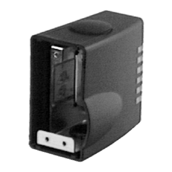
- Page 2 HMP-...-AD/-EL Bedienteile und Anschlüsse Operating parts and connections Abschlußdeckel mit 2 Schrauben M 3 an befestigt Sichtfenster für LED’s Bohrungen zur Befestigung des Abschlußmoduls Verschlußkappe für Kabel- austrittsöffnung Klemmleiste für Sensorenkabel Gelbe LED’s für Schaltzustandsan- zeige für sechs mögliche Sensoren Stecker für Sammelkabel Steckersockel Metallträger...
- Page 3 Funktion und Anwendung Function and application pneumatisch-elektrische The pneumatic-electric end module schlußmodul HMP-...-AD/-EL dient be- HMP-...-AD/-EL is used for grouping to- stimmungsgemäß zur zentralen Zufüh- gether the following supply lines: rung folgender Versorgungsleitungen: Mögliche zentrale Zuführung von Possible central grouping of Versorgungsleitungen supply lines HMP-...-AD...
- Page 4 HMP-...-AD/-EL Voraussetzungen für den Conditions of use Produkteinsatz Allgemeine, stets zu beachtende Hin- These general conditions for the correct weise für den ordnungsgemäßen und si- and safe use of the product must be ob- cheren Einsatz des Produkts: served at all times. •...
- Page 5 1. Die zwei Schrauben aus dem Ab- 1. Unscrew the two screws from the end schlußdeckel drehen (gut verwahren). cover (keep in a safe place). 2. Pull the end cover down from the Me- 2. Abschlußdeckel vom Metallträger herunterziehen. tallträger end module.
- Page 6 HMP-...-AD/-EL Electrical elektrisch • Use only power units which ensure • Verwenden Sie nur Netzteile, die reliable electrical isolation of the eine sichere elektrische Trennung der Betriebsspannung nach IEC 742/ operating voltages with at least 4 kV isolation resistance as per EN 60742/VDE 0551 mit mindestens IEC 742/ EN 60742/VDE 0551.
- Page 7 • Verkabeln Sie die elektrischen An- • Wire the electrical connections as fol- schlüsse wie folgt (siehe Bild 8 u. 9): lows (see Fig. 8 and 9): 1. Sensoren an der Klemmleiste verka- 1. Connect the terminal strip for the beln (auf Polung der Sensoren achten) sensors (check polarity of the sensors).
- Page 8 HMP-...-AD/-EL Inbetriebnahme Commissioning • Starten Sie einen Probelauf anhand • Start a test run with the operating in- der Bedienungsanleitung des Linear- structions with the linear module. modul. • Prüfen Sie im Probelauf, ob folgende • During the test run, check whether Punkte erfüllt sind: the following conditions are fulfilled: –...
- Page 9 Störungsbeseitigung Störung mögliche Ursache Abhilfe LED leuchtet nicht – Anschlußfehler beheben – unzulässige Kabelbiegung Jumpereinstellung an der HMP- Jumper an der HMP-...-EL ...-EL entspricht nicht dem gemäß Kapitel ’Einbau Schalterausgang der Sensoren elektrisch’ plazieren Druckluftversorgung Kabelschutzschlauch zu stark Zul. Mindest-Biegeradius unterbrochen gebogen einhalten (siehe Technische...
- Page 10 HMP-...-AD/-EL Technische Daten HMP-...-AD HMP-...-EL Bauart Pneumatisches Abschlußmodul Pneumatisch-elektrisches Abschlußmodul Einbaulage am hinteren Enddeckel des Linearmodul HMP-... gemäß Bohrbildcodierung Zulässiger Temperaturbereich 0 ... max. +60 Schutzart nach EN 60529 IP 40 IP 40 Zul. Leitungsquerschnitt – 0,08 ... max. 0,5 mm /AWG 28-20 Abisolierlänge –...
- Page 11 Technical specifications Type HMP-...-AD HMP-...-EL Design Pneumatic end module Pneumatic-electric end module Fitting position On rear end cover of linear module HMP-... Permitted temperature range 0 ... max. +60 Protection class as per EN 60529 IP 40 IP 40 Permitted cable cross section –...
- Page 12 Postfach 6040 D-73726 Esslingen Phone +49 / 711 / 347-0 Zubehör Accessories Quelltext: deutsch Version: 0001a Bezeichnung Designation Type Weitergabe sowie Vervielfätigung dieses Kabelschutz- MKR-... / MKG-... Protective MKR-... / MKG-... Dokuments, Verwertung und Mitteilung schlauch tubing seines Inhalts verboten, soweit nicht ausdrücklich gestattet.
Need help?
Do you have a question about the HMP AD Series and is the answer not in the manual?
Questions and answers