Advertisement
Quick Links
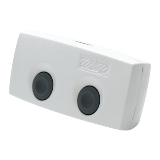
1142 SERIES WIRELESS
TWO-BUTTON TRANSMITTER
Installation Guide
Figure 1: 1142 Series Wireless
Two-Button Transmitter
DESCRIPTION
The 1142 Series are wireless two-
button hold-up transmitters that can
be mounted under a counter or on a
wall. They provide a tamper switch to
identify if the unit has been removed
from its mounted location. The 1142E
features 128-bit AES encryption.
The 1142BC wireless two-button
panic transmitter is designed to clip
to a belt or pocket. Optionally, the
1142BC can be mounted under the
counter or on a wall.
Both 1142 Series units provide two
buttons that, when pressed at the
same time, send a panic message to
the control panel. They also provide
an LED that can be programmed to
provide visual indication that a panic
alarm has been transmitted.
Compatibility
All DMP XT Series and XR Series and
all 1100 Series Wireless Receivers.
To enable encryption on 1142E
models, Version 183 is required
for XT and XR Series panels and
Version 300 is required for Wireless
Receivers.
What is Included?
• One 1142 Wireless Two-Button
Transmitter
• One 3.0V Lithium CR123A Battery
• Hardware Pack
• Belt Clip (If 1142BC was ordered)
1
PROGRAM THE PANEL
Refer to the panel programming guide as needed.
1.
At a keypad, enter 6653 (PROG) to access the Programmer
Menu.
Note: Steps 2 and 3 are for the 1142E to enable encryption. If
using an 1142, proceed to step 4 to continue the installation.
2.
(1142E only) Navigate to System Options. At the
1100 ENCRYPTION prompt, select ALL to only add encrypted
wireless devices to the system. Select BOTH to allow both
encyrpted and non-encrypted wireless devices to be
programmed.
3.
(1142E only) The default passphrase appears at the
ENTER PASSPHRASE prompt. Press CMD to keep the default.
Press any select key or area to change the passphrase and
enter an 8-character hexidecimal string (0-9, A-F).
4.
In ZONE INFORMATION, enter the wireless ZONE NO:.
Enter the ZONE NAME.
5.
Select PN (panic) as the ZONE TYPE.
6.
7.
At the NEXT ZN? prompt, select NO.
8.
Select YES when WIRELESS? displays.
Enter the eight-digit SERIAL# and press CMD.
9.
10. Enter in the SUPRVSN TIME (supervision time) and press CMD.
For the 1142BC applications where the transmitter may be
taken off-site, set the supervision time to zero (0).
11. At LED OPER (operation), select YES to activate or NO to
not activate the LED when a panic signal is transmitted or
acknowledged by the receiver. The LED pulses for five minutes
after the acknowledgement is received from the panel.
12. At the NEXT ZN? prompt, select YES if you are finished
programming the zone. Select NO if you would like to access
additional programming options.
2
OPEN THE 1142
Because of the strength and the snap-on design of the plastic, the
1142 can only be opened by using a 3/16" slotted tip screwdriver.
Insert the screwdriver in Tab 1 and twist it clockwise as
1.
seen in Figure 2.
Insert the screwdriver in Tab 2 and twist it
2.
counterclockwise until the housing completely opens.
Tab 2
Tab 1
Figure 2: Open the 1142
Advertisement

Subscribe to Our Youtube Channel
Related Manuals for DMP Electronics 1142 Series


Summary of Contents for DMP Electronics 1142 Series
- Page 1 In ZONE INFORMATION, enter the wireless ZONE NO:. Enter the ZONE NAME. Select PN (panic) as the ZONE TYPE. The 1142 Series are wireless two- button hold-up transmitters that can At the NEXT ZN? prompt, select NO. be mounted under a counter or on a wall.
- Page 2 INSTALL THE BATTERY Use a 3.0V lithium battery or a DMP Model CR123A battery. It is recommended for UL installations to use either an Energizer 123 battery or a CR123A battery manufactured by Panasonic or Tekcell. Keep in mind, when setting up a wireless system, program zones and connect the receiver (if needed) before installing the battery.
- Page 3 Install the Belt Clip BELT CLIP Set aside the top housing containing the PCB, Spacer battery, and LED. Align the belt clip spacer with the housing indention. Using the supplied screw, secure the belt clip to the housing. Insert Align the top housing and LED cut out with the base Screw housing and LED cut out and snap into place.
- Page 4 établies par le Code de sécurité 6 de Santé Canada. Le système doit être installé à une distance minimale de 7.87 pouces (20 cm) séparant l’antenne d’une personne présente en conformité avec les limites permises d’exposition du grand pub- lic. 1142 SERIES WIRELESS Ordering Information 1142-W Standard Wireless Two-Button Transmitter...
Need help?
Do you have a question about the 1142 Series and is the answer not in the manual?
Questions and answers