Table of Contents
Advertisement
Quick Links
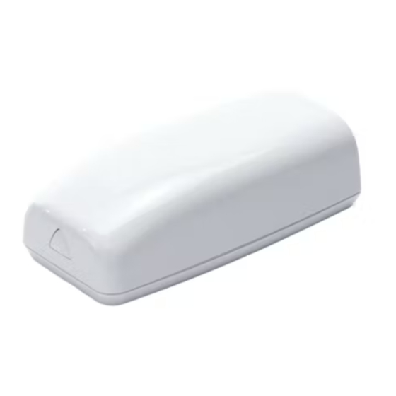
Description
The 1101 is a two-input transmitter that is typically used
for door and window applications. The 1101 provides two
internal magnetic reed switches and an on-board terminal
block to allow for external contact wiring. Both sets of
contacts, internal and external, can be programmed to
operate at the same time allowing for two independent
zones from one transmitter.
Using the on-board LED the 1101 Universal Transmitter
provides built-in survey capability to allow for single-person
installations, eliminating the requirement for an external
survey kit. For added security, an internal case tamper
switch is provided.
Compatibility
All DMP 1100 Series Wireless Receivers and Panels
Included Components
• One 1101 transmitter PCB mounted in a two-part housing (base and cover)
• One magnet housing and base
• One 3V lithium CR123A battery
• Hardware pack
Programming the Transmitter in the Panel
Program the device as a zone in Zone Information during panel programming. At the Serial Number: prompt, enter
the eight-digit serial number. Continue to program the zone as directed in the panel programming guide.
Note: When a receiver is installed, powered up, or the panel is reset, the supervision time for transmitters is reset.
If the receiver has been powered down for more than one hour, wireless transmitters may take up to an additional
hour to send a supervision message unless tripped, tampered, or powered up. This operation extends battery life for
transmitters. A missing message may display on the keypad until the transmitter sends a supervision message.
Selecting the Proper Location (LED Survey Operation)
The 1101 Transmitter provides a survey capability to allow one person to confirm transmitter communication
with the receiver while the cover is removed. The 1101 Transmitter PCB Red Survey LED turns on whenever data
is sent to the receiver then immediately turns off when the receiver acknowledgement is received. Pressing the
tamper switch is a convenient way to send data to the receiver to confirm operation. When the tamper switch is
pressed or released, the LED blinks once to indicate proper operation. When the transmitter does not receive an
acknowledgement from the receiver the LED remains on for about 8 seconds to let you know communication is
not established. Communication is also faulty when the LED flashes multiple times in quick succession. Relocate
the transmitter or receiver until the LED immediately turns off indicating the transmitter and receiver are
communicating properly. Proper communication between the transmitter and receiver is verified when for each press
or release of the tamper switch, the LED blinks immediately on and immediately off. Repeat this test to confirm five
separate consecutive LED blinks. Any indication otherwise means proper communication has not been established.
Mounting the Transmitter and Magnet Assemblies
For internal contact operation, the transmitter and magnet assembly should have no more than a 5/8" space
between the assembled housings after installation. When mounting on metal surfaces, this distance is slightly less.
For door installations, it is recommended the transmitter be mounted on the door frame and the magnet assembly
be mounted on the door. See Figure 2 for transmitter and magnet placement options.
1101 Universal Transmitter
Side Mounting
Figure 2. Transmitter and Magnet Placement Options
INSTALLATION GUIDE
Figure 1: Transmitter and Magnet
End Mounting
Advertisement
Table of Contents

Related Manuals for DMP Electronics 1101


Summary of Contents for DMP Electronics 1101
- Page 1 The 1101 Transmitter provides a survey capability to allow one person to confirm transmitter communication with the receiver while the cover is removed. The 1101 Transmitter PCB Red Survey LED turns on whenever data is sent to the receiver then immediately turns off when the receiver acknowledgement is received. Pressing the tamper switch is a convenient way to send data to the receiver to confirm operation.
- Page 2 • XTLplus Series - zones 3 and 4 Note: For UL listed installations, program the external contact as Normally Closed (N/C). Refer to the Contact option under Zone Information in the appropriate panel programming guide. Digital Monitoring Products 1101 Installation Guide...
- Page 3 Properly dispose of used batteries. Battery Life Expectancy Typical battery life expectancy for DMP Model 1101 wireless transmitters is 5 years. DMP wireless equipment uses two-way communication to extend battery life. The following situations can reduce battery life expectancy: •...
- Page 4 FCC Information This device complies with Part 15 of the FCC Rules. Operation is subject to the following two conditions: (1) This device may not cause harmful interference, and (2) this device must accept any interference received, including interference that may cause undesired operation. The antenna used for this transmitter must be installed to provide a separation distance of at least 20 cm from all persons.
Need help?
Do you have a question about the 1101 and is the answer not in the manual?
Questions and answers