
Subscribe to Our Youtube Channel
Related Manuals for GIGAIPC QBiX Jumbo Series


Summary of Contents for GIGAIPC QBiX Jumbo Series
-
Page 1: Qbix-Jwb Industrial Embedded System
QBiX-JWB-SKYA110H-A1 (QJ-H110A-SI) QBiX-JWB Industrial Embedded System Quick Start Guide www.gigaipc.com... -
Page 2: Copyright Notice
While reasonable efforts have been made in the preparation of this document to assure its accuracy, GIGAIPC assumes no liabilities resulting from errors or omissions in this document, or from the use of the information contained herein. -
Page 3: Acknowledgement
Core, Atom are trademarks of Intel Corporation • • ITE is a trademark of Integrated Technology Express, Inc. IBM, PC/AT, PS/2, and VGA are trademarks of International Business • Machines Corporation. All other product names or trademarks are properties of their respective owners. www.gigaipc.com... -
Page 4: Packing List
Before setting up your product, please make sure the following items have been shipped: Item Quantity System kit 1 pcs HDD screw, M3 x 8L 8 Pcs Exsiccator (10g) 1 pcs If any of these items are missing or damaged, please contact your distributor or sales representative immediately. www.gigaipc.com... -
Page 5: About This Document
(if any), its specifications, dimensions, jumper/ connector settings/definitions, and driver installation instructions (if any), to facilitate users in setting up their product. Users may refer to the GIGAIPC.com for the latest version of this document. www.gigaipc.com... -
Page 6: Safety Precautions
Make sure the device is installed near a power outlet and is easily accessible. 10. Keep this device away from humidity. 11. Place the device on a solid surface during installation to prevent falls 12. Do not cover the openings on the device to ensure optimal heat dissipation. www.gigaipc.com... - Page 7 20. D O N O T L E AV E T H I S D E V I C E I N A N U N C O N T R O L L E D ENVIRONMENT WITH TEMPERATURES BEYOND THE DEVICE’S PERMITTED STORAGE TEMPERATURES (SEE CHAPTER 1) TO PREVENT DAMAGE. www.gigaipc.com...
-
Page 8: Fcc Statement
Il y a un risque d’explosion si la batterie est remplacée de façon incorrecte. Ne la remplacer qu’avec le même modèle ou équivalent recommandé par le constructeur. Recycler les batteries usées en accord avec les instructions du fabricant et les directives gouvernementales de recyclage. www.gigaipc.com... -
Page 9: Table Of Contents
Industrial Embedded System Kit Dimension ..............18 Getting Familiar with Your Unit........19 Support ................ 21 Safety and Regulatory Information ....... 22 Chapter 3 – Hardware Information Jumpers and Connectors ..........24 3.2.1 AT_CN (AT/ATX power mode select jumper) ....27 www.gigaipc.com... - Page 10 3.2.15 JCOM11 (Default COM1 is RI pin, can select RI/5V/12V) ..................41 3.2.16 JCOM21 (Default COM2 is RI pin, can select RI/5V/12V) ..................42 3.2.17 JCOM12 (COM1 RS-232/RS-422/RS-485 Select) ..43 3.2.18 JCOM22 (COM2 RS-232/RS-422/RS-485 Select) ..44 3.2.19 JRS21-24 (COM2 JRS21-24 select jumper for serial port) ..................45 www.gigaipc.com...
- Page 11 The Main Menu ............58 Advanced Menu ............60 4.2.1 CPU Configuration Menu ..........61 4.2.2 A Trusted Computing Menu ......... 63 4.2.3 SATA and RST Configuration Menu ......64 4.2.4 Hardware Monitor Menu ..........65 4.2.5.1 Super IO Configuration Menu ........66 www.gigaipc.com...
- Page 12 OS Selection Menu ............69 4.2.8 Digital IO Port Configuration Menu ......70 Chipset Menu ..............71 Security Menu ............... 73 4.4.1 Secure Boot Menu ............74 4.4.2 Key Management Menu ..........75 Boot Menu ..............76 Save & Exit Menu ............77 www.gigaipc.com...
-
Page 13: Chapter 1 - Product Specifications
Chapter 1 Chapter 1 - Product Specifications www.gigaipc.com... - Page 14 99.0 92.6 www.gigaipc.com...
-
Page 15: Specifications
1 x Power & HDD LED 2 x Remote control header 4 x USB 2.0 Front I/O 4 x COM ports (RS-232/422/485) 1 x COM port (RS-232) 1 x GPIO (8 bit) 4 4r 2 x External Antenna Hole (Optional) www.gigaipc.com... - Page 16 Use wide temperature range memory and storage Vibration During Operation Shock During Operation Order Information 9BQJH110AMR-SI (Box packing) CPU: Intel® Core™ i3-7100T Processor, 3M Cache, 3.40 GHz Build in Memory: 4GB DDR4 SO-DIMM Components Storage: 128GB, 2280 M.2, SSD www.gigaipc.com...
-
Page 17: Chapter 2 - Qbix-Jwb-Skya110H-A1 (Qj-H110A-Si)
Chapter 2 Chapter 2 – QBiX-JWB-SKYA110H-A1 (QJ-H110A-SI) Industrial Embedded System Kit www.gigaipc.com... -
Page 18: Dimension
Dimension 99.0 92.6 www.gigaipc.com... -
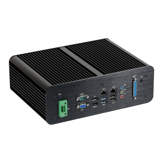
Page 19: Getting Familiar With Your Unit
Getting Familiar with Your Unit [Front Side] [Rear Side] Note: The LVDS output connector of the unit is only intended to be connected to an UL/IEC/EN approval equipment with fire enclosure. www.gigaipc.com... - Page 20 [Install] x Before opening the case, make sure to unplug the power cord. x Before Connecting the power, make sure to fasten the case securely. www.gigaipc.com...
-
Page 21: Support
Support ● For a list of tested memory, M.2, 2.5’’ SSD, wireless adapters and OS supported, go to: http://www.gigaipc.com ● To download the latest drivers and BIOS updates, go to: http://www. gigaipc.com ● For product support, go to: http://www.gigaipc.com www.gigaipc.com... -
Page 22: Safety And Regulatory Information
At the end of its serviceable life, this product should not be treated as household or general waste. It should be handed over to the applicable collection point for the recycling of electrical and electronic equipment, or returned to the supplier for disposal. www.gigaipc.com... -
Page 23: Chapter 3 - Hardware Information
Chapter 3 Chapter 3 – Hardware Information www.gigaipc.com... -
Page 24: Jumpers And Connectors
Jumpers and Connectors www.gigaipc.com... - Page 25 Default COM1 is RI pin, can select RI/5V/12V JCOM12 COM1 RS-232/RS-422/RS-485 Select JCOM21 Default COM2 is RI pin, can select RI/5V/12V JCOM22 COM2 RS-232/RS-422/RS-485 Select JRS21 RS21 select jumper for serial port for COM2 JRS24 RS24 select jumper for serial port for COM2 www.gigaipc.com...
- Page 26 Front panel header TPM_LPC TPM connector USB20_LAN2 USB 2.0 ports + GbE LAN port USB30_LAN1 USB 3.0 ports + GbE LAN port VGA (Bottom) VGA port COM1 (TOP) Serial port M.2 Slot, M-Key, SATA 6Gb/s & PCIe, Supports M2_M NGFF-2280 Card www.gigaipc.com...
-
Page 27: At_Cn (At/Atx Power Mode Select Jumper)
AT_CN (AT/ATX power mode select jumper) Pin 1 AT/ATX power mode select jumper Connector PN Vendor PH03N33BAAA00 HORNGTONG Pin No. Definition AT MODE Detect ATX MODE Jumper setting 1-2 Close : AT mode. 2-3 Close : ATX mode.(Default setting) www.gigaipc.com... -
Page 28: Battery
3.2.2 Battery Pin 1 Battery Cable Connector Connector PN Vendor 85205-0270L ACES A1250WV-S-02PC JOINT-TECH Pin No. Definition 3.3V www.gigaipc.com... -
Page 29: Bkl_Cn (Back Light Brightness Control Connector)
3.2.3 BKL_CN (Back light brightness control connector) Pin 1 Back light brightness control Connector PN Vendor connector 85205-0270L ACES A1250WV-S-02PC JOINT-TECH Pin No. Definition Back Light Enable www.gigaipc.com... -
Page 30: Clr_Cmos
3.2.4 CLR_CMOS Pin 1 Clear COMS Jumper Connector PN Vendor 210-91-02GB01 PINREX PH02R23BAZ000 HORNGTONG Pin No. Definition Clear CMOS Open: Normal Operation (Default setting) Close: Clear COMS data. www.gigaipc.com... -
Page 31: Com2 (Serial Port Header)
3.2.5 COM2 (Serial Port header) Pin 1 Serial Port Cable Connector Connector PN Vendor 725-81-10TW00 PINREX A2004WV-2X05P46 JOINT-TECH Definition Pin Definition No Connect RI/ 5V/ 12V www.gigaipc.com... -
Page 32: Cpu_Fan (Cpu Fan Connector)
3.2.6 CPU_FAN (CPU fan connector) Pin 1 CPU FAN Connector PN Vendor 744-81-045W11 PINREX WF04R22WJQ195 HORNGTONG Pin No. Definition Detect Speed Control www.gigaipc.com... -
Page 33: Dc_In (Dc In Jack Connector)
3.2.7 DC_IN (DC In JACK Connector) DC JACK Connector Connector PN Vendor 2MJ-3422A1I0 SINGATRON Note: *Connect only to a properly wired and ground outlet. www.gigaipc.com... -
Page 34: Dc_In2 (Atx 2X2 Pin Power Connector)
3.2.8 DC_IN2 (ATX 2x2 pin power connector) Pin 1 Power Connector Connector PN Vendor 740-81-04TW56 PINREX 25104A0400B3-93LF ATRC Note: *Connect only to a properly wired and ground outlet. Pin No. Definition +12V +12V www.gigaipc.com... -
Page 35: Edp (Embedded Display Port Connector)
3.2.9 EDP (Embedded Display Port Connector) Pin 1 Note: * Please ensure pin 8 is Embedded Display Port connector connected to Ground. Connector PN Vendor Definition Pin Definition A1252WV-SF- JOINT-TECH 2X10PN6BG1G00L 50286-02071-001 ACES AUX- AUX+ SW * 3.3V www.gigaipc.com... -
Page 36: F_Audio (Front Audio Header)
3.2.6 F_Audio (Front audio header) Pin 1 Front Audio Connector Connector PN Vendor 725-81-10TW00 PINREX A2004WV-2X05P46 JOINT-TECH Definition Pin Definition MIC_L MIC_R No Connect Detect HPOUT_L HPOUT_R www.gigaipc.com... -
Page 37: F_Usb 30 (Usb 3.0 Header)
3.2.11 F_USB 30 (USB 3.0 header) Pin 1 USB 3.0 Header Pin No. Definition P2_TX+ P2_TX- Pin No. Definition P2_RX+ Power P2_RX- P1_RX- Power P1_RX+ No Pin P1_TX- Connector PN Vendor P1_TX+ 52X-80-20GU65 PINREX WUIR-19A9N4BU3W WINWIN P1_D- P1_D+ P2_D+ P2_D- www.gigaipc.com... -
Page 38: F_Usb 20_1 (Usb 2.0 Header)
3.2.12 F_USB 20_1 (USB 2.0 header) Pin 1 USB 2.0 Header Connector PN Vendor 210-92-05GB04 PINREX PH10R53BAZ009 HORNGTONG Pin No. Definition No Pin No Connect www.gigaipc.com... -
Page 39: F_Usb 20_2 (Usb 2.0 Header)
3.2.13 F_USB 20_2 (USB 2.0 header) Pin 1 USB 2.0 Header Connector PN Vendor 210-91-05GB02 PINREX PH05R23BAZ005 HORNGTONG Pin No. Definition www.gigaipc.com... -
Page 40: 3.2.14 Gpio_Cnt
3.2.14 GPIO_CNT Pin 1 GPIO Connector Pin No. Definition SMB_CLK SMB_DATA Connector PN Vendor Pin No. Definition 725-81-12TW00 PINREX GPO1 GPI1 A2004WV-2X06P46 JOINT-TECH GPO2 GPI2 GPO3 GPI3 GPO4 GPI4 www.gigaipc.com... - Page 41 3.2.15 JCOM11 (Default COM1 is RI pin, can select RI/5V/12V) Pin 1 JCOM11 Jumper Connector PN Vendor 220-97-03GB01 PINREX 1-2 Close: PH06N53BAZ000 HORNGTONG 5V (Power COM) 3-4 Close: RI (Stand COM)(Default) 5-6 Close: 12V (Power COM) www.gigaipc.com...
- Page 42 3.2.16 JCOM21 (Default COM2 is RI pin, can select RI/5V/12V) Pin 1 JCOM11, JCOM21 Jumper Connector PN Vendor 220-97-03GB01 PINREX 1-2 Close: PH06N53BAZ000 HORNGTONG 5V (Power COM) 3-4 Close: RI (Stand COM)(Default) 5-6 Close: 12V (Power COM) www.gigaipc.com...
-
Page 43: Jcom12 (Com1 Rs-232/Rs-422/Rs-485 Select)
3.2.17 JCOM12 (COM1 RS-232/RS-422/RS-485 Select) Pin 1 JCOM12 Jumper Pin No. Definition RX232 1-2 Close: RS-232 (Default) RX422 3-4 Close: RX485 RS-422 5-6 Close: RS-485 Connector PN Vendor 220-97-03GB01 PINREX PH06N53BAZ000 HORNGTONG www.gigaipc.com... -
Page 44: Jcom22 (Com2 Rs-232/Rs-422/Rs-485 Select)
3.2.18 JCOM22 (COM2 RS-232/RS-422/RS-485 Select) Pin 1 JCOM22 Jumper Pin No. Definition RX232 1-2 Close: RS-232 (Default) RX422 3-4 Close: RX485 RS-422 5-6 Close: RS-485 Connector PN Vendor 222-97-03GBE1 PINREX www.gigaipc.com... -
Page 45: Jrs21-24 (Com2 Jrs21-24 Select Jumper For Serial Port)
RS-485 Half Duplex 1T/1R RS-485, TX ENABLE Low Active RS-485 Half Duplex 1T/1R RS-485, TX ENABLE High Active RS-422 Full Duplex 1T/1R RS-422 with termination resistor and bias resistor. 1T/1R RS-485 with termination resistor and bias resistor. RS-485 Half Duplex TX ENABLE Low Active www.gigaipc.com... -
Page 46: Jrs 11-14 (Com1 Jrs11-14 Select Jumper For Serial Port)
RS-485 Half Duplex 1T/1R RS-485, TX ENABLE Low Active RS-485 Half Duplex 1T/1R RS-485, TX ENABLE High Active RS-422 Full Duplex 1T/1R RS-422 with termination resistor and bias resistor. 1T/1R RS-485 with termination resistor and bias resistor. RS-485 Half Duplex TX ENABLE Low Active www.gigaipc.com... -
Page 47: Lsw (Lvds Resolution Jumper)
1024 x 600 1600 x 900 18bit 24bit 1280 x 800 1680 x 1050 18bit 24bit 1280 x 960 1600 x 1200 18bit 24bit 1280 x 1024 1920 x 1080 24bit 24bit 1366 x 768 1920 x 1200 18bit 24bit www.gigaipc.com... -
Page 48: Lvds (Lvds Connector)
Definition Pin No. Definition 3.3V 3.3V Connector PN Vendor 712-76-40GWE0 PINREX SPEC0 SPED0 A1252WV-SF-2X20PD01 JOINT-TECH Note: *The LVDS output connector of the unit is only intended to be connected to an UL/IEC/EN approval equipment with fire enclosure. CLK2+ CLK1+ www.gigaipc.com... - Page 49 3.2.23 SATAIII_0, SATAIII_1, SATAIII_2 (SATA 6GB/s Connector) SATA Connector SATAIII_1,SATAIII_0 Connector PN Vendor WATM-07ABNB2BAUW3 WINWIN 770-83-07SW19 PINREX SATAIII_2 Connector PN Vendor ASAT0014-P008C LOTES Definition Pin Definition www.gigaipc.com...
-
Page 50: Satapw_1, Satapw_2 (Sata 6Gb/S Power Connector)
3.2.24 SATAPW_1, SATAPW_2 (SATA 6GB/s Power Connector) 34 35 Pin 1 Hard Disk Power Connector Connector PN Vendor 743-81-04TW00 PINREX WF04Q2-3BJQ000 HORNGTONG Pin No. Definition www.gigaipc.com... -
Page 51: Spk_Out (Speaker Out Connector)
3.2.25 SPK_OUT (Speaker out Connector) Pin 1 Audio Amplifie Connector Connector PN Vendor 721-81-045W00 PINREX A2001WV-04P146 JOINT-TECH Pin No. Definition Speaker Out L+ Speaker Out L- Speaker Out R- Speaker Out R+ www.gigaipc.com... -
Page 52: Sys_Fan (System Fan Connector)
3.2.26 SYS_FAN (System Fan Connector) Pin 1 System FAN Connector PN Vendor 744-81-045R11 PINREX WF04R22RJQ105 HORNGTONG Pin No. Definition Detect Speed Control www.gigaipc.com... -
Page 53: Sys_Panel (Front Panel Header)
3.2.27 SYS_PANEL (Front Panel Header) Pin 1 System Panel Header Connector PN Vendor 210-92-05G111 PINREX Pin No. Definition HDD LED+ Power LED+ HDD LED- Power LED- Power Button+ Reset Button Power Button- No Connect No Pin www.gigaipc.com... -
Page 54: Tpm_Lpc (Trusted Platform Module Connector)
3.2.28 TPM_LPC (Trusted Platform Module Connector) Pin 1 TPM Module Connector Pin No. Definition TPM_DET LAD2 LAD3 Pin No. Definition LFRAME LPCCLK 3VDUAL PFM RST VCC3 Connector PN Vendor LAD0 52M-90-14GBE7 PINREX IRQ_SERIAL LAD1 www.gigaipc.com... -
Page 55: M2_M (M.2 Slot, M-Key, Sata 6Gb/S & Pcie, Supports Ngff-2280/2242 Card)
3.2.29 M2_M (M.2 Slot, M-Key, SATA 6Gb/s & PCIe, Supports NGFF-2280/2242 Card) www.gigaipc.com... - Page 56 www.gigaipc.com...
-
Page 57: Chapter 4 - Bios
Chapter 4 Chapter 4 – BIOS www.gigaipc.com... -
Page 58: The Main Menu
• When the system is not stable as usual, select the Restore User Defaults item to set your system to its defaults. • The BIOS Setup menus described in this chapter are for reference only and may differ by BIOS version. www.gigaipc.com... - Page 59 » LAN1/2 MAC Address » Total Memory Displays the technical specifications for the installed memory. » ME FW Version » System Date Set the date following the weekday-month-day- year format. » System Time Set the system time following the hour-minute- second format. www.gigaipc.com...
-
Page 60: Advanced Menu
Advanced Menu The Advanced menu display submenu options for configuring the function of various hardware components. Select a submenu item, and then press Enter to access the related submenu screen. www.gigaipc.com... -
Page 61: Cpu Configuration Menu
Enables or disables Intel® Virtualization Technology. Virtualization enhanced by Intel® Virtualization Technology will allow a platform to run multiple operating systems and applications in independent partitions. With virtualization, one computer system can function as multiple virtual systems. Options available: Enabled/Disabled. Default setting is Enabled www.gigaipc.com... - Page 62 Options available: Enabled/Disabled. Default setting is Enabled » Intel® Speed Shift Technology Enables or disables support for Intel® Speed Shift Technology Options available: Enabled/Disabled. Default setting is Enabled » CFG lock Enable/Disable CFG lock. Options available: Enabled/Disabled. Default setting is Disabled www.gigaipc.com...
-
Page 63: A Trusted Computing Menu
4.2.2 A Trusted Computing Menu » Security Device Support Select Enabled to activate TPM support feature. Options available: Enabled/Disabled. Default setting is Disabled. www.gigaipc.com... -
Page 64: Sata And Rst Configuration Menu
The hard disk will not work properly if you enter improper information for this category. Hard drive information should be labeled on the outside device casing. Enter the appropriate option based on this information. www.gigaipc.com... -
Page 65: Hardware Monitor Menu
4.2.4 Hardware Monitor Menu » CPU / System Temperature Displays current system/ CPU temperature. » VCORE/ DDR1.2V/ +12V/ VCC/ VCC3 Displays a real-time record of the related system voltage. www.gigaipc.com... -
Page 66: 4.2.5.1 Super Io Configuration Menu
4.2.5.1 Super IO Configuration Menu » Serial Port 1 Configuration Press [Enter] for configuration of advanced items. www.gigaipc.com... -
Page 67: 4.2.5.2 Serial Port 1/2 Configuration Menu
Disabled, displays no configuration for the serial port. Options available: Enabled/Disabled. Default setting is Enabled. » Device Settings Display the specified Serial Port base I/O address and IRQ. » Mode Select Mode of serial port. Options available: RS232 / RS485 / RS485&RS422 Default setting is RS232. www.gigaipc.com... -
Page 68: S5 Rtc Wake Settings Menu
Press <+> and <-> to define the wake up hour. » Wake up minute (Note) Press <+> and <-> to define the wake up minute. » Wake up second (Note) Press <+> and <-> to define the wake up second. www.gigaipc.com... -
Page 69: Os Selection Menu
Enabled/Disabled. Default setting is Disabled. If the CSM is set to Disabled, the following five items will not be able to support Legacy mode. » LAN EFI driver Enable/Disable LAN EFI driver. Options available: Enabled/Disabled. Default setting is Disabled www.gigaipc.com... -
Page 70: Digital Io Port Configuration Menu
» SOGPO_1 / 2 / 3 / 4 Set the GPIO port as Input or output. Options available: Input / Output Default setting is Output. » Select Level Select Output Level High or Low. Options available: High / Low Default setting is High. www.gigaipc.com... -
Page 71: Chipset Menu
Default setting is Enabled. » DVMT Pre-Allocated Select DVMT 5.0 Pre-Allocated (Fixed) Graphics Memory size used by the Internal Graphics Device. Options available: 32M/64M/128M/256M. Default setting is 64M. » Onboard Audio Enable/Disable onboard audio controller. Options available: Enabled/Disabled. Default setting is Enabled. www.gigaipc.com... - Page 72 Default setting is Power Off. » WatchDog Timer Force system reboot if system gang up by memory detection fail. This option provides user to set watchdog timer as default. Options available: Disabled / 15s / 30s / 60s Default setting is Disabled. www.gigaipc.com...
-
Page 73: Security Menu
A user can only access and modify the System Time, System Date, and Set User Password fields. » Administrator Password Press Enter to configure the Administrator password. » User Password Press Enter to configure the user password. » Secure Boot menu Press [Enter] for configuration of advanced items. www.gigaipc.com... -
Page 74: Secure Boot Menu
This way, the system knows all the files being loaded before Windows 8 loads and gets to the login screen have not been tampered with. Options available: Enabled/Disabled. Default setting is Disabled. www.gigaipc.com... -
Page 75: Key Management Menu
» Secure Boot Mode (Note) Define the Secure Boot Mode. Set this item to Custom to advanced items configuration. Option available: Standard/Custom. Default setting is Custom. » Key Management Press Enter to configure the advanced items. 4.4.2 Key Management Menu www.gigaipc.com... -
Page 76: Boot Menu
The Boot menu allows you to set the drive priority during system boot- up. BIOS setup will display an error message if the drive(s) specified is not bootable. » Boot Option Priorities » Boot Option #1 / #2 / #3 Press Enter to configure the boot priority. www.gigaipc.com... -
Page 77: Save & Exit Menu
Highlight any of the exit options then press Enter. » Save Changes and Reset Saves changes made and reset the system. Options available: Yes/No. » Discard Changes and Reset Discards changes made and reset the system. Options available: Yes/No. www.gigaipc.com... - Page 78 If you are using low-speed memory chips or other kinds of low- performance components and you choose to load these settings, the system might not function properly. Options available: Yes/No. » Me FW Image Re-Flash Enable/Disable Me FW Image Re-Flash function. Options available: Enabled/Disabled. Default setting is Disabled. www.gigaipc.com...
Need help?
Do you have a question about the QBiX Jumbo Series and is the answer not in the manual?
Questions and answers