
Related Manuals for GIGAIPC QBiX-Lite-TGLA1135G7-A1


Summary of Contents for GIGAIPC QBiX-Lite-TGLA1135G7-A1
-
Page 1: Qbix-Lite Industrial Embedded System
QBiX-Lite-TGLA1135G7-A1 QBiX-Lite-TGLA1145G7E-A1 QBiX-Lite Industrial Embedded System Quick Start Guide www.gigaipc.com... -
Page 2: Copyright Notice
While reasonable efforts have been made in the preparation of this document to assure its accuracy, GIGAIPC assumes no liabilities resulting from errors or omissions in this document, or from the use of the information contained herein. -
Page 3: Acknowledgement
Core, Atom are trademarks of Intel Corporation ITE is a trademark of Integrated Technology Express, Inc. • • IBM, PC/AT, PS/2, and VGA are trademarks of International Business Machines Corporation. All other product names or trademarks are properties of their respective owners. www.gigaipc.com... -
Page 4: Packing List
PSU ADP 19.5V 135W 100-240VAC (25EP4-201352-C1S) 1 Power Cord (Optional, by region) Thermal Pad for Memory (25ST3-200086-T5R) SATA Cable (25CRI-180002-S9R) Screws for 2.5” HDD #2-M3x4L (25KS2-13004G-S0R) Exsiccator (10g) If any of these items are missing or damaged, please contact your distributor or sales representative immediately. www.gigaipc.com... -
Page 5: About This Document
(if any), its specifications, dimensions, jumper/ connector settings/definitions, and driver installation instructions (if any), to facilitate users in setting up their product. Users may refer to the GIGAIPC.com for the latest version of this document. www.gigaipc.com... -
Page 6: Safety Precautions
Make sure the device is installed near a power outlet and is easily accessible. 10. Keep this device away from humidity. 11. Place the device on a solid surface during installation to prevent falls 12. Do not cover the openings on the device to ensure optimal heat dissipation. www.gigaipc.com... - Page 7 18. D O N O T L E AV E T H I S D E V I C E I N A N U N C O N T R O L L E D ENVIRONMENT WITH TEMPERATURES BEYOND THE DEVICE’S PERMITTED STORAGE TEMPERATURES (SEE CHAPTER 1) TO PREVENT DAMAGE. www.gigaipc.com...
-
Page 8: Fcc Statement
Il y a un risque d’explosion si la batterie est remplacée de façon incorrecte. Ne la remplacer qu’avec le même modèle ou équivalent recommandé par le constructeur. Recycler les batteries usées en accord avec les instructions du fabricant et les directives gouvernementales de recyclage. www.gigaipc.com... -
Page 9: Table Of Contents
(Wireless Module inclusion may vary based on local distribution) ..............22 B) Memory Installation: DDR4 SO-DIMM ....23 Antenna Installation (Antenna inclusion may vary based on local distribution) ............ 24 DB9 COM Pin Define ........... 25 Support ................ 26 Safety and Regulatory Information ....... 27 www.gigaipc.com... - Page 10 3.2.19 HDMI_DP_1, HDMI_DP_2 (HDMI (Bottom) & DP (Top) connector) ..............50 3.2.20 LAN1, LAN2 (LAN Connector) ........51 3.2.21 USB3CM (USB 3.2 Gen 2x1 Type C connector) ..... 52 3.2.22 USB3CP (USB 3.2 Gen 2x1 Type C connector) ....52 www.gigaipc.com...
- Page 11 Chapter 4 – BIOS Introduction ..............57 The Main Menu............. 58 Advanced ..............59 4.3.1.1 Advanced menu items for QBiX-Lite-TGLA1135G7-A1 59 4.3.1.2 Advanced menu items for QBiX-Lite-TGLA1145G7E-A1 ..................59 4.3.2 A M T C o n f i g u r a t i o n ( F o r M o d e l Q B i X - L i t e - TGLA1145G7E-A1 only) ..........
- Page 12 Chipset ................80 Security ................. 81 Boot ................84 Save & Exit ..............85 www.gigaipc.com...
-
Page 13: Chapter 1 - Product Specifications
Chapter 1 Chapter 1 - Product Specifications www.gigaipc.com... - Page 14 171.54 130.0 155.00 30.00 154.20 136.20 130.00 37.00 40.00 40.00 www.gigaipc.com...
-
Page 15: Specifications
Specifications System QBiX-Lite-TGLA1135G7-A1 QBiX-Lite-TGLA1145G7E-A1 (QL-1135A-SI) (QL-1145A-SI) Dimension System Size : 234W x 155D x 30H (mm) Intel® Core™ i5-1135G7 Intel® Core™ i5-1145G7E Processor Processor 10nm SuperFin, 4 cores, 10nm SuperFin, 4 cores, 8 threads, up to 4.2 GHz 8 threads, up to 4.1 GHz Chipset 2 x DDR4 SO-DIMM sockets, Max. - Page 16 System QBiX-Lite-TGLA1135G7-A1 QBiX-Lite-TGLA1145G7E-A1 (QL-1135A-SI) (QL-1145A-SI) 1 x COM Port (RS-232) 2 x USB 2.0 Rear I/O 1 x Headphone Jack 1 x Screw type DC Jack 2 x External Antenna Holes (Optional) Side I/O 1 x External Antenna Hole (on each side) Power +12V~24VDC (Adapter 19.5V/135W)
-
Page 17: Chapter 2 - Qbix- Lite -Tgl A1135G7-A1/Qbix- Lite - Tgla1145G7E-A1 Industrial Embedded System Kit
Chapter 2 Chapter 2 – QBiX-Lite-TGLA1135G7-A1 QBiX-Lite-TGLA1145G7E-A1 Industrial Embedded System Kit www.gigaipc.com... -
Page 18: Dimension
Dimension 171.54 130.0 155.00 30.00 154.20 136.20 130.00 37.00 40.00 40.00 www.gigaipc.com... -
Page 19: Dimension - Including Wall Mount Brackets
16.3 268.6 253.6±0.3 30.0±0.3 235.0±0.3 149.0 30.5 24.4 80.0 268.6±0.3 NOTE : The wall mount bracket will be shipped as an accessory instead of assembled on the system. Above dimension drawing including wall mount backets is for reference only. www.gigaipc.com... -
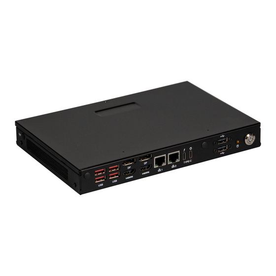
Page 20: Getting Familiar With Your Unit
It does not support hot swap. ※ Note 2 : When plug-in 100W adapter into USB Type C (USB3CM) port, power max of USB Type C (USB3CP) would restrict to 36W (12V/3A) only, to maintain stable of the system. www.gigaipc.com... - Page 21 2 x DDR4 SO-DIMM sockets, Max. 1 x 2230 M.2 E-Key Capacity 64 GB, Support Dual 1 x 2280 M.2 M-Key Channel DDR4 3200 MHz (PCIe x2, SATA 6Gb/s) 1 x 3052 M.2 B-Key with SIM Slot Support 2.5’’ Hard drive/ SSD (Support 5G) www.gigaipc.com...
-
Page 22: A) Wireless Module: How To Safely Install The Module (Wireless Module Inclusion May Vary Based On Local Distribution)
Module (Wireless Module inclusion may vary based on local distribution) Carefully insert the wireless module into Lock the screw in the middle. the M.2 slot 鎖入固定於無線模組中央頂端的螺 小心地將無線模組安裝於M.2插槽中。 絲。 青山依舊在,幾度夕陽紅。慣看秋月春風。一 壺濁酒喜相逢,浪花淘盡英雄。是非成敗轉頭 Install the antenna on the left side of the connection wireless module down. 向下安裝連結於無線模組左側頂端天線。 www.gigaipc.com... -
Page 23: B) Memory Installation: Ddr4 So-Dimm
B) Memory Installation: DDR4 SO-DIMM SO-DIMM www.gigaipc.com... -
Page 24: Antenna Installation (Antenna Inclusion May Vary Based On Local Distribution)
Antenna Installation (Antenna inclusion may vary based on local distribution) www.gigaipc.com... -
Page 25: Db9 Com Pin Define
DB9 COM Pin Define DB9 COM 25CF8-120600-S9R Pin No. Pin Define www.gigaipc.com... -
Page 26: Support
Support ● For a list of tested memory, M.2, 2.5’’ SSD, wireless adapters and OS supported, go to: http://www.gigaipc.com ● To download the latest drivers and BIOS updates, go to: http://www. gigaipc.com ● For product support, go to: http://www.gigaipc.com www.gigaipc.com... -
Page 27: Safety And Regulatory Information
At the end of its serviceable life, this product should not be treated as household or general waste. It should be handed over to the applicable collection point for the recycling of electrical and electronic equipment, or returned to the supplier for disposal. www.gigaipc.com... -
Page 28: Chapter 3 - Hardware Information
Chapter 3 Chapter 3 – Hardware Information www.gigaipc.com... -
Page 29: Jumpers And Connectors
Jumpers and Connectors 22 21 www.gigaipc.com... - Page 30 Embedded Display Port power connector PCIE_X4 PCIe Gen3 x4 connector M.2 Slot, SATA/PCIex2, NGFF 2280 SODIMM1 DDR4 SO-DIMM Slot SODIMM2 Trusted Platform Module connector USB31_1 USB 3.2 Gen 2x1 connector USB31_2 HDMI_DP_1 DP connector (Top) HDMI_DP_2 HDMI connector (Bottom) LAN1, LAN2 LAN connector www.gigaipc.com...
- Page 31 Code Description USB3CM USB 3.2 Gen 2x1 Type C connector (Output) USB3CP USB 3.2 Gen 2x1 Type C connector (Input) M.2 Slot, E-key, NGFF2230, WiFi & Bluetooth module M.2 Slot, B-key, NGFF3052 BATTERY Battery cable connector www.gigaipc.com...
-
Page 32: Cpu_Fan2 (Cpu Fan Connector)
3.2.1 CPU_FAN2 (CPU fan connector) Pin 1 CPU fan Connector Connector PN Vendor 85205-0470N ACES A1250WV-S-04PC JOINT-TECH Pin No. Definition Detect Speed control www.gigaipc.com... -
Page 33: Edp (Embedded Display Port Connector)
Pin 1 Embedded Display Port Connector Pin No. Definition Pin No. Definition EDP_TX2+ EDP_TX3- EDP_TX3+ Pin No. Definition Pin No. Definition Connector PN Vendor 115B20-100020-G4-R STARCONN EDP_TX0- EDP_AUX- EDP_TX0+ EDP_AUX+ Hotplug EDP_TX1- Detect Backlight EDP_TX1+ Enable Backlight EDP_TX2- cotrol www.gigaipc.com... -
Page 34: Fusb1, Fusb2 (Usb2.0 Headers)
3.2.3 FUSB1, FUSB2 (USB2.0 headers) Pin 1 USB 2.0 Header Connector PN Vendor 210-92-05GB04 PINREX PH10R53BAZ009 HORNGTONG 9 10 Pin No. Definition No Pin No Connect www.gigaipc.com... -
Page 35: Dc_In (Dc In 1X4 Pin Power Connector)
3.2.4 DC_IN (DC IN 1x4 pin power connector) Pin 1 DC IN 1x4 pin power connector Connector PN Vendor 753-81-04TW00 PINREX 1 2 34 Pin No. Definition POWER IN POWER IN www.gigaipc.com... -
Page 36: Sys_Panel (Front Panel Header)
3.2.5 SYS_PANEL (Front panel header) Pin 1 System Panel Header Connector PN Vendor 210-92-05G111 PINREX 210-92-05GW5W PINREX Pin No. Definition HDD LED+ Power LED+ HDD LED- Power LED- Power Button+ Reset Power Button- No Connect No Pin www.gigaipc.com... -
Page 37: Com (Serial Port Header, Rs-232)
3.2.6 COM (Serial port header, RS-232) Pin 1 Serial Port Cable Connector Connector PN Vendor 725-81-10TW00 PINREX A2004WV-2X05P46 JOINT-TECH Definition Definition No Connect RI/ 5V/ 12V www.gigaipc.com... -
Page 38: Fp_Audio (Front Audio Connector)
3.2.7 FP_AUDIO (Front Audio connector) Pin 1 Front Audio Connector Connector PN Vendor 725-81-10TW00 PINREX A2004WV-2X05P46 JOINT-TECH Definition Pin Definition MIC_L MIC_JD FAUDIO_JD MIC_R No Connect Detect HPOUT_L HPOUT_R www.gigaipc.com... -
Page 39: Satapwr (Sata Power Connector)
3.2.8 SATAPWR (SATA power connector) Pin 1 Hard Disk Power Connector Connector PN Vendor 743-91-045W00 PINREX A2540WR- JOINT-TECH 04PR6NG1N10G Pin No. Definition www.gigaipc.com... -
Page 40: Spkr (Speaker Out Connector)
3.2.9 SPKR (Speaker out connector) Pin 1 Speaker out Connector Connector PN Vendor 721-81-045W00 PINREX A2001WV-04P146 JOINT-TECH Pin No. Definition Speaker Out L+ Speaker Out L- Speaker Out R- Speaker Out R+ www.gigaipc.com... -
Page 41: Me (Me Enable Jumper)
3.2.10 ME (ME Enable jumper) ME Enable Connector Connector PN Vendor 220-96-02GB01 PINREX ME Enable jumper Enable (Default) Disable (Close) www.gigaipc.com... -
Page 42: Sata0 (Sata 6Gb/S Connector)
3.2.11 SATA0 (SATA 6Gb/s connector) SATA Connector Connector PN Vendor WATF-07DBLBA1UW WINWIN Pin No. Definition www.gigaipc.com... -
Page 43: Jcom1 (Com1 Ri# Pin Ri#/5V/12V Select)
3.2.12 JCOM1 (COM1 RI# pin RI#/5V/12V Select) JCOM1 Jumper Select Connector PN Vendor 222-97-03GBE1 PINREX 1-2 Close: 5V (Power COM) 3-4 Close: RI (Stand COM) (Default-Setting) 5-6 Close: 12V (Power COM) www.gigaipc.com... -
Page 44: Edp_Pwr (Embedded Display Port Power Connector)
3.2.13 ED P_ P WR (Emb e d de d D i s p lay Po r t p ower connector) Pin 1 Embedded Display Port power Connector PN Vendor connector 85205-0770N ACES A1250WV-S-07PC JOINT-TECH Pin No. Definition www.gigaipc.com... -
Page 45: Pcie_X4 (Pcie Gen3 X4 Connector)
Pin No. Definition Pin No. Definition RX0_DP RX0_DN CK_REQ CLK_DP CLK_DN SMB_CLK SMB_DATA PLT_RST# PCIE_WAKE# Pin No. Definition Pin No. Definition TX3_DP TX3_DN Connector PN Vendor TX2_DP 115B30-000040-G4-R STARCONN TX2_DN TX1_DP TX1_DN TX0_DP TX0_DN RX3_DP RX3_DN RX2_DP RX2_DN RX1_DP RX1_DN www.gigaipc.com... -
Page 46: M2M (M.2 Slot, Sata/Pciex2, Ngff 2280)
Pin No. Definition Pin No. Definition CK_REQ 3.3V CLK_N PCIE_WAKE# 3.3V CLK_P Pin No. Definition Pin No. Definition M2_LED SUSCLK 3.3V M2_SSD_ 3.3V 3.3V Detect 3.3V 3.3V 3.3V 3.3V Connector PN Vendor 2E0BC41-C85CM-LH FOXCONN PCIE_RXN PCIE_RXP PCIE_TXN PCIE_ TXP DEVSLP www.gigaipc.com... -
Page 47: Sodimm1, Sodimm2 (Ddr4 So-Dimm Slot)
3.2.16 SODIMM1, SODIMM2 (DDR4 SO-DIMM Slot) www.gigaipc.com... -
Page 48: Tpm (Trusted Platform Module Connector)
3.2.17 TPM (Trusted Platform Module Connector) Pin 1 TPM Module Connector Connector PN Vendor 87216-1004-06 ACES Pin No. Definition Pin No. Definition TPM_CLK SPI_CS TPM_SO TPM_RST# TPM_SI 3.3V www.gigaipc.com... -
Page 49: Usb31_1, Usb31_2 (Usb 3.2 Gen 2X1 Connector)
3.2.18 USB31_1, USB31_2 (USB 3.2 Gen 2x1 Connector) USB Connector Connector PN Vendor 18-A5950-6A33-A TCONN Definition Definition USB_D- USB_D- USB_D+ USB_D+ USB3_RX- USB3_RX- USB3_RX+ USB3_RX+ USB3_TX- USB3_TX- USB3_TX+ USB3_TX+ www.gigaipc.com... -
Page 50: Connector)
Pin No. Definition Pin No. Definition Pin No. Definition HDMI_D2+ DATA_0P DATA_3N HDMI_D2- HDMI_SCL DATA_0N CONFIG1 HDMI_D1+ HDMI_SDA DATA_1P AUX_P HDMI_D1- DATA_1N HDMI_D0+ HDMI_HPD DATA_2P AUX_N DP HPD HDMI_D0- DATA_2N DATA_3P DP PWR HDMI_CLK+ Connector PN Vendor HDMI_CLK- DPHDDPHD0172201AN0 FENYING www.gigaipc.com... -
Page 51: Lan1, Lan2 (Lan Connector)
LAN Connector State Description Orange On 1Gbps data rate Green On 100Mbps data rate 10Mbps data rate Link / Connection/ Activity LED Speed LED Pin No. Definition Connector PN Vendor TX+_D1 RB1-GB-0008 TX-_D1 RX+_D2 BI+_D3 BI-_D3 RX-_D2 BI+_D4 BI-_D4 www.gigaipc.com... -
Page 52: Usb3Cm (Usb 3.2 Gen 2X1 Type C Connector)
3.2.22 USB3CP (USB 3.2 Gen 2x1 Type C connector) Input Output USB Type C Connector Connector PN Vendor WU3CR- WINWIN 24A5L1CU5T41 Pin No. Definition Pin No. Definition TX1+ TX2+ TX1- TX2- VBUS VBUS VBUS VBUS RX2- RX1- RX2+ RX1+ www.gigaipc.com... -
Page 53: M2E (M.2 Slot, E-Key, Ngff2230, Wifi & Bluetooth Module)
M.2 E Key Connector WLAN_RXN CL_CLK CLK_DP CLK_DN SUSCLK Pin No. Definition Pin No. Definition CLK_REQ PLT_RST# PCIE_WAKE BT_Disable# WIFI_Disable# USB_D+ USB_D- BT_WAKE Connector PN Vendor APCI0095-P002A LOTES Pin No. Definition Pin No. Definition 80152-8521 BELLWETHER WLAN_TXP WLAN_TXN CL_RST# www.gigaipc.com... -
Page 54: M2B (M.2 Slot, B-Key, Ngff3052)
3.3V CLK_N CK_REQ WWAN_PWR_ CLK_P PCIE_WAKE WWAN_ USB D+ Disable USB D- Pin No. Definition Pin No. Definition GPP_RESET M2B_DET 3.3V M2B_WAKE 3.3V M2B_DRP 3.3V WWAN_ Disable2 Connector PN Vendor USB3 RXN 80149-8521 BELLWETHER USB3_RXP SIM_RST# SIM_CLK USB3_TXN SIM_DATA www.gigaipc.com... -
Page 55: Battery (Battery Cable Connector)
3.2.25 BATTERY (Battery cable Connector) Pin 1 Battery cable Connector Connector PN Vendor 85205-0270L ACES A1250WV-S-02PC JOINT-TECH Pin No. Definition 3.3V www.gigaipc.com... -
Page 56: Chapter 4 - Bios
Chapter 4 Chapter 4 – BIOS www.gigaipc.com... -
Page 57: Introduction
Execute command or enter the submenu Increase the numeric value or make + changes Decrease the numeric value or make – changes General Help Previous Values Load Optimized Defaults Settings Save changes & Exit the BIOS Setup program Exit the BIOS Setup program www.gigaipc.com... -
Page 58: The Main Menu
ME FW version Shows ME firmware version Set the Date for the system System Date (Format : Week - Month - Day - Year) Set the time for the system System Time (Format : Hour - Minute - Second) www.gigaipc.com... -
Page 59: Advanced
The Advanced menu is to configure the functions of hardware settings through submenu. Use arrow keys to move among the items, and press <Enter> to access into the related submenu. 4.3.1.1 Advanced menu items for QBiX-Lite-TGLA1135G7-A1 4.3.1.2 Advanced menu items for QBiX-Lite-TGLA1145G7E-A1 www.gigaipc.com... -
Page 60: Amt Configuration
AMT Disabled : Disables USB Provisioning of AMT Enabled : Enables USB Provisioning of AMT (Default setting) Disabled : Disables MAC Pass Through function MAC Pass (Default setting) Through Enabled : Enables MAC Pass Through function www.gigaipc.com... - Page 61 CIRA Configuration Item Description Trigger CIRA boot Activate Remote Disabled : Disables TPM feature (Default setting) Assistance Process Enabled : Enables TPM feature www.gigaipc.com...
- Page 62 Disabled : Disables watchdog Timer (Default setting) Enabled : Enables watchdog Timer OS Timer Sets OS Watchdog Timer. BIOS Timer Sets BIOS Timer. ASF Sensors Disabled : Disables ASF Sensors Table (Default setting) Table Enabled : Enables ASF Sensors Table www.gigaipc.com...
- Page 63 Simulated : Performs SE flow without erasing SSD Secure Erase mode (Default setting) Real : Erase SSD Force Secure Erase on next boot. Force Secure Erase Disabled : Disables Force Secure Erase (Default setting) Enabled : Enables Force Secure Erase www.gigaipc.com...
- Page 64 Disabled : Disables MEBx OEM Debug Menu Enable Debug Menu (Default setting) Enable Enabled : Enables MEBx OEM Debug Menu Enable To Un-configure ME without password. Unconfigure ME Disabled : Disables Unconfigure ME (Default setting) Enabled : Enables Unconfigure ME www.gigaipc.com...
- Page 65 Option items : Auto (Default setting), 80x25, 100x31 Resolution for UI text mode. UI Mode Resolution Option items : Auto (Default setting), 80x25, 100x31 Resolution for graphics mode. Graphics Mode Option items : Auto (Default setting), 640x480, 800x600, Resolution 1024x768 www.gigaipc.com...
-
Page 66: Tpm Configuration
4.3.2 TPM Configuration Use TPM Configuration submenu to choose TPM interface. Item Description PTT : Internal TPM (Default setting) TPM Device dTPM : External TPM (When using External TPM module or Selection having TPM chip on MB) www.gigaipc.com... - Page 67 Item Description Security Device Enabled : Enables TPM feature (Default setting) support Disabled : Disables TPM feature None : No execution will be conducted (Default setting) Pending operation TPM clear : Set to clear data on TPM www.gigaipc.com...
-
Page 68: Sata And Rst Configuration
Intel VMD feature helps you to control and manage NVMe PCIe SSD. / Enable VMD Enabled : Enables Intel VMD feature controller Disabled : Disables Intel VMD feature (Default setting) Serial ATA Port 0 shows 2.5" SATA HDD/SSD information shows M.2 SATA interface SSD information www.gigaipc.com... -
Page 69: Cpu Configuration
To speed up CPU frequency transition time from basic frequency to maximum frequency. Intel(R) Speed Enabled : Enables Intel(R) Speed Shift Technology Interrupt control (Default Shift Technology setting) Interrupt control Disabled : Disables Intel(R) Speed Shift Technology Interrupt control www.gigaipc.com... -
Page 70: Super I/O Configuration
Serial Port 1 Enabled : Enables allows you to configure the serial port settings Disabled : if Disabled, displays no configuration for the serial port Configuration Device settings : Display the specified Serial Port base I/O address and IRQ www.gigaipc.com... -
Page 71: Hardware Monitor
Normal : Fan speed set by BIOS default (Default setting) Control Full Speed : Set Fan operates at full speed CPU temperature Shows current CPU temperature System Shows current system temperature temperature Fan Speed Shows current CPU fan Speed www.gigaipc.com... -
Page 72: S5 Rtc Wake Settings
Enable or Disable System to wake on a specific time. Wake system Disabled : Disables system to wake on a specific time (Default setting) from S5 Fixed Time : Enables system to wake on a specific time (Format : hr : min : sec) www.gigaipc.com... -
Page 73: Serial Port Console Redirection (For Model Qbix-Lite-Tgla1145G7E-A1 Only)
Flow Control : None (Default setting), Hardware RTS/CTS VT-UTF8 Combo Key Support : Disableds, Enabled (Default setting) Recorder Mode : Disabled (Default setting), Enabled Resolution 100x31 : Disabled (Default setting), Enabled Putty KeyPad : VT100 (Default setting), LINUX, XTERMR6, SCO, ESCN, VT400 www.gigaipc.com... - Page 74 Item Description Legacy Console Redirection Settings : Redirection COM Port : COM0 (Default setting), COM1 (Pci, Bus0, Dev0, Legacy Console Func0) (Disabled) Redirection Resolution : 80x24 (Default setting), 80x25 Redirect After POST : Always Enable (Default setting), BootLoader www.gigaipc.com...
- Page 75 Out-of-Band Mgmt Port : COM0 (Default setting), COM1 (Pci, Bus0, Dev0, Emergency Func0) (Disabled) Management Terminal Type EMS : VT100, VT100+, VT-UTF8 (Default setting), ANSI Services (EMS) Bits per second EMS : 9600, 19200, 57600, 115200 (Default setting) Flow Control EMS : None (Default setting), Hardware RTS/CTS, Software Xon/Xoff www.gigaipc.com...
-
Page 76: Tgla1145G7E-A1 Only)
I n t e l T X T I n f o r m a t i o n ( F o r M o d e l Q B i X - L i t e - TGLA1145G7E-A1 only) This submenu shows detailed Intel TXT informations. www.gigaipc.com... -
Page 77: Network Stack Configuration
When Network stack is enabled : Ipv4 PXE Support Disabled : Disables Ipv4 PXE Support Enabled : Enables Ipv4 PXE Support When Network stack is enabled : Ipv6 PXE Support Disabled : Disables Ipv6 PXE Support Enabled : Enables Ipv6 PXE Support www.gigaipc.com... -
Page 78: Nvme Configuration
4.3.11 NVMe Configuration NVMe Configuration shows information when your M.2 NVMe PCIe SSD is installed. www.gigaipc.com... -
Page 79: Offboard Sata Controller Configuration
4.3.12 Offboard SATA Controller Configuration www.gigaipc.com... - Page 80 Enable/Disable Watchdog Timer function Watchdog Timer Enabled : Enables Watchdog Timer function Disabled : Disabled Watchdog Timer function (Default setting) Enable/Disable BIOS Lock function BIOS Lock Enabled : Enables BIOS Lock function (Default setting) Disabled : Disabled BIOS Lock funtion www.gigaipc.com...
- Page 81 To set up Administrator's password Administrator Minimum length : 3 Password Maximum length : 20 To set up User's password User Password Minimum length : 3 Maximum length : 20 Secure Boot Press <Enter> to configure the advanced items www.gigaipc.com...
- Page 82 No : Cancel to restore factory settings Reset To Setup Yes : Agree to setup mode Mode No : Cancel to setup mode Enables expert users to modify Secure boot policy variables without full Key Management authentication Press <Enter> to configure the advanced items www.gigaipc.com...
- Page 83 'UEFI CA' from database from DB No : Cancel to remove 'UEFI CA' from database Restore DB variables to fac tor y Restore DB defaults defaults Yes : Agree to restore DB defaults No : Cancel to restore DB defaults www.gigaipc.com...
- Page 84 Enabled : Enables Full screen LOGO Show on POST screen LOGO Show Disabled : Disables Full screen LOGO Show on POST screen (Default setting) Shows the information of the storage that be installed in the system Boot Option #1 Choose/set the boot priority www.gigaipc.com...
- Page 85 Yes : Agree to load optimized defaults No : Cancel to load optimized defaults Enable/Disable Me FW image re-flash function Me FW Image Enabled : Enables Me FW image re-flash function Re-Flash Disabled : Disables Me FW image re-flash function (Default setting) www.gigaipc.com...
Need help?
Do you have a question about the QBiX-Lite-TGLA1135G7-A1 and is the answer not in the manual?
Questions and answers