Table of Contents
Advertisement
Quick Links
Advertisement
Table of Contents

Related Manuals for Simons Voss Technologies SmartHandle AX


Summary of Contents for Simons Voss Technologies SmartHandle AX
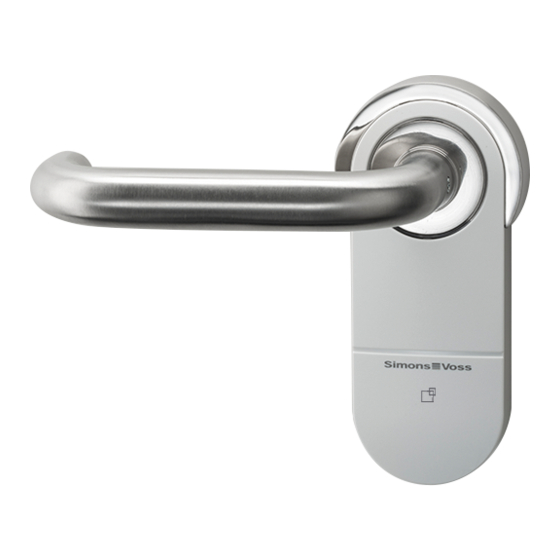
- Page 1 SmartHandle AX Manual 08.05.2020...
-
Page 2: Table Of Contents
General safety instructions........................ 8 Product-specific safety instructions.................... 12 Versions................................ 13 Mechanical Override (MO)......................... 13 Profiles.................................. 13 Fastening................................ 13 Distances and door thicknesses...................... 14 PAS24.................................. 15 SmartHandle AX without electronics .................... 15 Spindle ................................ 15 Network ................................ 16 Handle variants............................... 16 5.10 Surface finishes.............................. 17 5.11 Reader technology ............................ 17 5.12... - Page 3 Contents SmartHandle AX (Manual) 3 / 178 6.5.4 Procedure (BKS) ......................... 83 6.5.5 Procedure (CISA) ......................... 97 6.5.6 Information for panic bar....................... 109 Variants E0 and E1 (Scandinavian Oval) .................. 109 6.6.1 Contents of packaging...................... 110 6.6.2 Tools.............................. 110 6.6.3 Procedure............................ 111 LockNode (LNI) ............................ 127 6.7.1...
- Page 4 Contents SmartHandle AX (Manual) 4 / 178 13.1 Instructions on battery replacement.................... 148 13.2 Procedure ............................... 148 Maintenance, cleaning and disinfection.................. 151 Disassembly............................. 152 15.1 Variant A0 (vertical)........................... 152 15.2 Variant A1/A2 (suspended short/long)..................... 153 15.3 Variant A3 (steel frame) .......................... 155 15.4 Variant A4 (Panic bar) ..........................
-
Page 5: Intended Use
1 Intended use Products in the SmartHandle AX range consist of electronic door fittings. Users can engage the SmartHandle AX and open the door onto which it is fitted with an authorised ID medium, such as a transponder. The corresponding authorisations need to be issued using an electronic locking plan. -
Page 6: General
2. General SmartHandle AX (Manual) 6 / 178 2 General SmartHandle AX an electronic fitting which can be used to open and close doors. Electronic fittings from this series are available in the following models (also see Versions [ 13]... - Page 7 2. General SmartHandle AX (Manual) 7 / 178 Digital SmartHandle AX Description Digital door fitting for mounting on prepared metal frame doors Suitable for handle locks with a Euro Variant A3 Profile Outer side operated with identification ...
-
Page 8: General Safety Instructions
3. General safety instructions SmartHandle AX (Manual) 8 / 178 3 General safety instructions Possible immediate effects of non- Signal word (ANSI Z535.6) compliance DANGER Death or serious injury (likely) Death or serious injury (possible, but WARNING unlikely) CAUTION Minor injury... - Page 9 3. General safety instructions SmartHandle AX (Manual) 9 / 178 IMPORTANT Damage resulting from electrostatic discharge (ESD) This product contains electronic components that may be damaged by electrostatic discharges. 1. Use ESD-compliant working materials (e.g. Grounding strap). 2. Ground yourself before carrying out any work that could bring you into contact with the electronics.
- Page 10 3. General safety instructions SmartHandle AX (Manual) 10 / 178 IMPORTANT Failure of operation due to different discharged batteries This product uses one or more batteries for power supply. The batteries are discharged at approximately the same rate. Always replace all batteries at the same time.
- Page 11 3. General safety instructions SmartHandle AX (Manual) 11 / 178 NOTE Dispose of the batteries as per local and country-specific regulations. NOTE Function error due to poor battery contact If the contact surface to the battery is too small, then the battery connec- tion may not create a stable connection to the battery.
-
Page 12: Product-Specific Safety Instructions
Use only the supplied SimonsVoss opening tool. NOTE Effect on the mortise lock The SmartHandle AX acts exclusively on the latch of the mortise lock. NOTE Locking and insurances Insurance companies place increased demands on a closure. 1. If you want to lock the door under insurance law, use a self-locking panic lock or a locking cylinder in addition to the SmartHandle AX. -
Page 13: Versions
Cut-out for the cylinder concealed on both sides (completely concealed and invisible cylinder) 5.2 Profiles Choose from the following mortise lock profiles for your SmartHandle AX: Euro profile cylinder Swiss Round Scandinavian Oval 5.3 Fastening You can use the following fastening variants:... -
Page 14: Distances And Door Thicknesses
5. Versions SmartHandle AX (Manual) 14 / 178 Fastening You fix the SmartHand- le AX on adapter Steel frame mounting Variant A3 (steel plates. These adapter with (optional) mech- frame) [ 63] plates are screwed to anical overriding the steel frame using rivet nuts. -
Page 15: Pas24
5.6 SmartHandle AX without electronics SmartHandle AX is also available (for example for design purposes) without electronics. The square is then always continuous and the door can therefore be operated from both sides without an identification medium. -
Page 16: Network
10 mm version of the SmartHandle AX) 5.8 Network You can equip the SmartHandle AX with a network node at any time (see LockNode (LNI) [ 127] ). You do not need to exchange components to do this. -
Page 17: Surface Finishes
Alternatively, the SmartHandle AX is also available without electronics or permanently coupled. 5.12 Access control (ZK) and time zone control Access Control With this option, your SmartHandle AX can store up to 1500 accesses. A saved entry consists of:... - Page 18 Time zone control In addition, the time zone option also allows you to control the time zone. You can then program your SmartHandle AX in such a way that certain identification media are only authorised for access at certain times. You can create up to 64000 different time zone plans in each G2 locking system or 100+1 time zone groups in each G2 lock.
-
Page 19: Installation
(Manual) 19 / 178 6 Installation You can programme the SmartHandle AX while it is still in the packaging (except MP) and then install it. You will also find information on installing the SmartHandle AX in the accompanying quick guide. - Page 20 6. Installation SmartHandle AX (Manual) 20 / 178 Quantity Object Outer fitting assembly, incl: 1× 4× Battery (CR2450) 1× Inlay Outside handle, incl: 1× 1× headless screw Inside handle, incl: 1× headless screw 1× pre-assembled escut- 1× cheon base 1×...
-
Page 21: Tools
6. Installation SmartHandle AX (Manual) 21 / 178 Quantity Object 1× Dummy cylinder (FH version only) 1× Quick guide with integrated drilling template 6.2.2 Tools You require the following tools for installation: TX-15 screwdriver PH2 screwdriver Suitable pliers for shortening screws, e.g. mechanic's nippers ... -
Page 22: Procedure
6. Installation SmartHandle AX (Manual) 22 / 178 6.2.3 Procedure Preparing drill holes Diameter A Drill B 5.5 - 6.3 mm 8.5 mm 6.4 - 7.3 mm 8.5 mm 7.4 - 8.7 mm 9.5 mm 8.8 or greater 10.5 mm... - Page 23 6. Installation SmartHandle AX (Manual) 23 / 178 1. Pull out the mortise lock.
- Page 24 6. Installation SmartHandle AX (Manual) 24 / 178 2. Measure the diameter of the fixing holes on the mortise lock.
- Page 25 6. Installation SmartHandle AX (Manual) 25 / 178 3. Slide the mortise lock back into the door. 4. Insert the square into the mortise lock. 5. Using the square and the recess in the drilling template, position the drilling template on the door.
- Page 26 6. Installation SmartHandle AX (Manual) 26 / 178 6. Use a pointed object (e.g. pin needle) to pierce the position of the drill holes in the door. 7. Remove the drilling template. 8. Remove the square. 9. Remove the mortise lock.
- Page 27 6. Installation SmartHandle AX (Manual) 27 / 178 11. Drill the holes in the door. 12. Reassemble the mortise lock. Drill holes are prepared. Carry out programming NOTE Duration of initial programming A large amount of data is transferred during initial programming. The data transfer speed is higher with a SmartCD.MP (and the programming time is...
- Page 28 Locking device added in LSM software. ü LSM software launched. Programming device connected. ü 1. Position the programming device. 2. Programme the SmartHandle AX (see , quick guide or LSM manual for details). SmartHandle AX is programmed. Shorten screws Screw/Square Length 2×...
- Page 29 6. Installation SmartHandle AX (Manual) 29 / 178 1. Measure the thickness of the door (D). 2. Calculate the screw lengths (see table). 3. Select suitable predetermined breaking points that are no more than 3 mm from the calculated length.
- Page 30 6. Installation SmartHandle AX (Manual) 30 / 178 4. Separate the predetermined breaking points with pliers. Screws are shortened. NOTE X-variant If you have ordered version X for very thick doors, your delivery includes an extra long square rod and threaded rods together with extension sleeves. In this case the length specification refers to the total length of the screw (= screw, extension sleeve and threaded rod).
- Page 31 6. Installation SmartHandle AX (Manual) 31 / 178 Identify door direction The preparation of the inside handle varies depending on the opening side of the door (DIN R or DIN L). DIN L - Left stop DIN R - Right stop Compare the diagram with your door and prepare the inside handle ...
- Page 32 6. Installation SmartHandle AX (Manual) 32 / 178 2. Position the spring sub-assembly at an angle to the escutcheon base until it touches the switching plate. 3. Draw the spring sub-assembly back, so that the spring is compressed. 4. Slide the spring sub-assembly pawls into the escutcheon base.
- Page 33 6. Installation SmartHandle AX (Manual) 33 / 178 Prepare inside handle (*DIN R) 1. Insert the switching plate as shown.
- Page 34 6. Installation SmartHandle AX (Manual) 34 / 178 2. Position the spring sub-assembly at an angle to the escutcheon base until it touches the switching plate. 3. Draw the spring sub-assembly back, so that the spring is compressed. 4. Slide the spring sub-assembly pawls into the escutcheon base.
- Page 35 6. Installation SmartHandle AX (Manual) 35 / 178 Insert square NOTE 7 mm square The 7 mm square only fits into the 8 mm receptacle of the SmartHandle AX with an adapter shoe (included in the scope of delivery for the 7 mm version).
- Page 36 6. Installation SmartHandle AX (Manual) 36 / 178 Slide the square into the outer assembly of the SmartHandle AX until the pin engages the square. Square is inserted. Mounting the Assembly 1...
- Page 37 2. Plug the adapter sleeves onto your SmartHandle AX. 3. Insert your SmartHandle AX into the door from the outside. 4. Insert the escutcheon base into the door from the outside. 5. Insert the special sleeve nuts into the escutcheon base.
- Page 38 7 mm square The 7 mm square only fits into the 8 mm receptacle of the inside handle of the SmartHandle AX with an adapter sleeve (supplied with the 7 mm ver- sion). Before mounting, insert the adapter sleeve on the free side of the ...
- Page 39 6. Installation SmartHandle AX (Manual) 39 / 178 Mounting the Assembly 3 1. If necessary (FH variant), insert the dummy cylinder into the cylinder opening. 2. Place the inside handle on the square. 3. Tighten the base of the internal handle with the L1 screws (PH2, torque: 1.1 Nm).
- Page 40 6. Installation SmartHandle AX (Manual) 40 / 178 Mounting the Assembly 4 1. Screw the dummy cylinder tight (PH2, torque: 1.1 Nm). 2. Tighten the headless screw of the inside handle (T15, torque: 5.0 Nm). 3. Push the cover onto the base of the inside handle until it clicks into place (recess in the cover fits the nose of the base).
- Page 41 41 / 178 Mounting the Assembly 5 Push the escutcheon onto the outer escutcheon base until it clicks into place (recess in the escutcheon fits the nose of the escutcheon base). SmartHandle AX is mounted without an outside handle.
- Page 42 SmartHandle AX (Manual) 42 / 178 Mounting the outside handle 1. Push the outside handle onto the receptacle on the SmartHandle AX until it clicks into place. 2. Tighten the headless screw of the external handle (T15, torque: 5.0 Nm).
-
Page 43: Variants A1 And A2 (Suspended Mounting)
6. Installation SmartHandle AX (Manual) 43 / 178 6.3 Variants A1 and A2 (suspended mounting) 6.3.1 Contents of packaging Quantity Object Outer fitting assembly, incl: 1× 4× Battery (CR2450) 1× Inlay Outside handle, incl: 1× 1× headless screw Inside handle, incl: 1×... -
Page 44: Tools
6. Installation SmartHandle AX (Manual) 44 / 178 6.3.2 Tools You require the following tools for installation: TX-15 screwdriver PH2 screwdriver Suitable pliers for shortening screws, e.g. mechanic's nippers (X-variant: Saw for shortening square, e.g. hacksaw) ... - Page 45 6. Installation SmartHandle AX (Manual) 45 / 178 1. Pull out the mortise lock.
- Page 46 6. Installation SmartHandle AX (Manual) 46 / 178 2. Measure the distance between the mounting holes of your mortise lock (distance).
- Page 47 6. Installation SmartHandle AX (Manual) 47 / 178 3. Slide the mortise lock back into the door. 4. Insert the square into the mortise lock. 5. Using the square and the recess in the drilling template, position the drilling template on the door.
- Page 48 6. Installation SmartHandle AX (Manual) 48 / 178 7. Use a pointed object (e.g. pin needle) to pierce the position of the drill holes in the door. 8. Remove the drilling template. 9. Remove the square. 10. Remove the mortise lock.
- Page 49 6. Installation SmartHandle AX (Manual) 49 / 178 11. Drill the holes in the door (Ø 8.5 mm). 12. Reassemble the mortise lock. Drill holes are prepared. Carry out programming NOTE Duration of initial programming A large amount of data is transferred during initial programming. The data transfer speed is higher with a SmartCD.MP (and the programming time is...
- Page 50 Locking device added in LSM software. ü ü LSM software launched. Programming device connected. ü 1. Position the programming device. 2. Programme the SmartHandle AX (see , quick guide or LSM manual for details). SmartHandle AX is programmed. Shorten screws Screw/Square Length 2× L1 T - 8 mm (± 3 mm)
- Page 51 6. Installation SmartHandle AX (Manual) 51 / 178 NOTE X-variant If you have ordered version X for very thick doors, your delivery includes an extra long square rod and threaded rods together with extension sleeves. In this case the length specification refers to the total length of the screw (= screw, extension sleeve and threaded rod).
- Page 52 6. Installation SmartHandle AX (Manual) 52 / 178 Prepare inside handle (DIN R) The assembly varies depending on the opening side of the door (DIN R or DIN L). 1. Insert the switching plate as shown. 2. Position the spring sub-assembly at an angle to the escutcheon base until it touches the switching plate.
- Page 53 6. Installation SmartHandle AX (Manual) 53 / 178 4. Slide the spring sub-assembly pawls into the escutcheon base. 5. Press the rear clip into the designated pawl. Spring plate is inserted.
- Page 54 6. Installation SmartHandle AX (Manual) 54 / 178 Prepare the inside handle (DIN L) The assembly varies depending on the opening side of the door (DIN R or DIN L). 1. Insert the switching plate as shown.
- Page 55 6. Installation SmartHandle AX (Manual) 55 / 178 2. Position the spring sub-assembly at an angle to the escutcheon base until it touches the switching plate. 3. Draw the spring sub-assembly back, so that the spring is compressed. 4. Slide the spring sub-assembly pawls into the escutcheon base.
- Page 56 6. Installation SmartHandle AX (Manual) 56 / 178 Insert square...
- Page 57 6. Installation SmartHandle AX (Manual) 57 / 178 NOTE If you use a 7 mm spindle, attach the adapter shoe to the spindle before fit- ting the spindle. Insert the spindle into the outer sub-assembly until the pin locks into the ...
- Page 58 6. Installation SmartHandle AX (Manual) 58 / 178 Mounting the assembly 1. Push the sub-assembly with the spindle into the door from the outer side. 2. Position the escutcheon base for the cylinder opening on the other side of the door.
- Page 59 6. Installation SmartHandle AX (Manual) 59 / 178 4. Place the inner side handle on the spindle. 5. Screw the handle to the assembly with the L1 screws (PH2, torque: 1.1 Nm). NOTE Press the handle downwards if there is not enough room.
- Page 60 6. Installation SmartHandle AX (Manual) 60 / 178 6. Screw the headless screw into the handle to fix it in place (T15, torque: 5.0 Nm)
- Page 61 6. Installation SmartHandle AX (Manual) 61 / 178 7. Slide the escutcheon along the handle and press the escutcheon onto the escutcheon base until it locks into position. 8. Press the escutcheon onto the escutcheon base on the cylinder opening until it locks into place.
-
Page 62: Glass Door Fitting
5.0 Nm) SmartHandle AXassembled. 6.3.4 Glass door fitting You can also use an A1 SmartHandle AX design with an optional lock case on glass doors. The glass door must feature the following holes for SimonsVoss glass door fittings (dimensions in mm):... -
Page 63: Variant A3 (Steel Frame)
6. Installation SmartHandle AX (Manual) 63 / 178 6.4 Variant A3 (steel frame) 6.4.1 Contents of packaging Quantity Object Outer fitting assembly, incl: 1× 4× Battery (CR2450) 1× Inlay... -
Page 64: Tools
6. Installation SmartHandle AX (Manual) 64 / 178 Quantity Object Outside handle, incl: 1× 1× headless screw Inside handle, incl: 1× headless screw 1× pre-assembled escut- 1× cheon base adapter plate Screws for adapter plate Screws for escutcheon base (cylinder) -
Page 65: Procedure
6. Installation SmartHandle AX (Manual) 65 / 178 PH2 screwdriver PH1screwdriver Rivet nut pliers for M5 thread (X-variant: Saw for shortening square, e.g. hacksaw) 6.4.3 Procedure Preparing drill holes... - Page 66 6. Installation SmartHandle AX (Manual) 66 / 178 1. Pull out the mortise lock. 2. Measure the distance between the mounting holes of your mortise lock (distance). 3. Slide the mortise lock back into the door. 4. Insert the square into the mortise lock.
- Page 67 6. Installation SmartHandle AX (Manual) 67 / 178 7. Use a pointed object (e.g. pin needle) to pierce the position of the drill holes in the door. 8. Remove the drilling template. 9. Remove the square. 10. Remove the mortise lock.
- Page 68 6. Installation SmartHandle AX (Manual) 68 / 178 12. Deburr the drill holes so that the blind rivet nuts fit flat later. 13. Reassemble the mortise lock. Drill holes are prepared. Programme NOTE Duration of initial programming A large amount of data is transferred during initial programming. The data transfer speed is higher with a SmartCD.MP (and the programming time is...
- Page 69 LSM software launched. ü ü Programming device connected. 1. Position the programming device. 2. Programme the SmartHandle AX (see , quick guide or LSM manual for details). SmartHandle AX is programmed. Preparing the square NOTE Shorten the square of the extra long version (X) The square of the extra long version is supplied with 200 mm.
- Page 70 6. Installation SmartHandle AX (Manual) 70 / 178 Set blind rivet nuts ü Holes for blind rivet nuts available. Mount the blind rivet nuts with the rivet nut pliers in the holes of the steel frame.
- Page 71 6. Installation SmartHandle AX (Manual) 71 / 178 Blind rivet nuts are set. Mounting the outer fitting Blind rivet nuts set. ü 1. Screw the adapter plate to the outside (PH2, torque: 1.1 Nm).
- Page 72 6. Installation SmartHandle AX (Manual) 72 / 178 2. Screw the escutcheon base to the outside (PH2, torque: 1.1 Nm). NOTE Alignment of the adapter plate The adapter plate contains spring elements and creates a form fit with the fitting. Make sure that the spring elements are located on the adapter plate on ...
- Page 73 6. Installation SmartHandle AX (Manual) 73 / 178 3. Insert the fitting into the adapter plate.
- Page 74 6. Installation SmartHandle AX (Manual) 74 / 178 4. Slide the fitting down as far as it will go.
- Page 75 6. Installation SmartHandle AX (Manual) 75 / 178 5. Screw the fitting tight (PH1, torque: 0.8 Nm). 6. Replace the cover of the outer escutcheon base.
- Page 76 6. Installation SmartHandle AX (Manual) 76 / 178 7. Fit the outer handle. 8. Attach the outer cover. Outer fitting is mounted. Preparing the square Door thickness (S, M, L or X) and ring position Notch 1 Notch 2 Notch 3 Notch 4 38-43 mm...
- Page 77 6. Installation SmartHandle AX (Manual) 77 / 178 Door thickness (S, M, L or X) and ring position Ring is not used. Slide the ring onto the correct notch of the square. Square is prepared. Mount square and dummy cylinder 1.
- Page 78 6. Installation SmartHandle AX (Manual) 78 / 178 3. If necessary, screw the dummy cylinder tight (torque: 1.1 Nm). Square and dummy cylinder mounted. Mounting the inside handle 1. Screw down the inside handle (PH2, torque: 1.1 Nm). 2. Screw the escutcheon base on the inside (PH2, torque: 1.1 Nm).
-
Page 79: Variant A4 (Panic Bar)
3. Tighten the headless screw on both handles (T15, torque: 5.0 Nm). 4. Fit the cover of the inside handle. 5. Replace the inlay of the inner escutcheon base. SmartHandle AX is fully assembled. 6.5 Variant A4 (Panic bar) 6.5.1 Package contents (BKS) - Page 80 6. Installation SmartHandle AX (Manual) 80 / 178 Quantity Object Outer fitting assembly, incl: 1× 4× Battery (CR2450) 1× Inlay Outside handle, incl: 1× 1× headless screw 1× Adapter plate (pre-bent) 1× Spacer sleeve for adapter plate with square head Screw for mounting the fitting to the adapter plate (1×...
-
Page 81: Package Contents (Cisa)
6. Installation SmartHandle AX (Manual) 81 / 178 6.5.2 Package contents (CISA) Quantity Object Outer fitting assembly, incl: 1× 4× Battery (CR2450) 1× Inlay Outside handle, incl: 1× 1× headless screw 1× Adapter plate (pre-bent) with welded-on sleeve nut 1×... - Page 82 6. Installation SmartHandle AX (Manual) 82 / 178 NOTE Use a saw instead of pliers for shortening If no suitable pliers are available to shorten the screws, you can alternat- ively use a hacksaw. T15 screwdriver PH2 screwdriver ...
-
Page 83: Procedure (Bks)
6. Installation SmartHandle AX (Manual) 83 / 178 6.5.4 Procedure (BKS) Preparing drill holes... - Page 84 6. Installation SmartHandle AX (Manual) 84 / 178 1. Remove the mortise lock. 2. Measure the distance between the mounting holes of your mortise lock (distance).
- Page 85 6. Installation SmartHandle AX (Manual) 85 / 178 3. Slide the mortise lock back into the door. 4. Insert the square into the mortise lock. 5. Using the square and the recess in the drilling template, position the drilling template on the door.
- Page 86 6. Installation SmartHandle AX (Manual) 86 / 178 7. Use a pointed object (e.g. pin needle) to pierce the position of the BKS drill holes in the door. 8. Remove the drilling template. 9. Remove the square. 10. Remove the mortise lock.
- Page 87 6. Installation SmartHandle AX (Manual) 87 / 178 12. Reassemble the mortise lock. Drill holes are prepared. Programme NOTE Duration of initial programming A large amount of data is transferred during initial programming. The data transfer speed is higher with a SmartCD.MP (and the programming time is therefore shorter).
- Page 88 LSM software launched. ü Programming device connected. ü 1. Position the programming device. 2. Programme the SmartHandle AX (see , quick guide or LSM manual for details). SmartHandle AX is programmed. Preparing square and screws 1. Measure the thickness of your door.
- Page 89 6. Installation SmartHandle AX (Manual) 89 / 178 Preparing the fitting 1. Insert the spacer sleeve into the adapter plate. 2. Place the fitting against the adapter plate from the opposite side. NOTE Aligning the holes of the fitting and adapter plate Offset holes in the adapter plate and threaded mountings in the fitting make installation more difficult.
- Page 90 6. Installation SmartHandle AX (Manual) 90 / 178 3. Tighten the fitting crosswise with the first two fixing screws (PH2, torque: 1.1 Nm).
- Page 91 6. Installation SmartHandle AX (Manual) 91 / 178 4. Tighten the other two screws crosswise (PH2, torque: 1.1 Nm). 5. Slide the square into the square socket of the fitting.
- Page 92 6. Installation SmartHandle AX (Manual) 92 / 178 Mounting the fitting and fastening the support plate 1. Insert the prepared fitting into the door from the outside. 2. Push the escutcheon base onto the adapter plate. 3. Insert the two sleeve nuts into the escutcheon base.
- Page 93 6. Installation SmartHandle AX (Manual) 93 / 178...
- Page 94 6. Installation SmartHandle AX (Manual) 94 / 178 5. Screw the escutcheon base on the inside (L2 screws with PH2, torque: 1.1 Nm). The fitting is fixed.
- Page 95 6. Installation SmartHandle AX (Manual) 95 / 178 Mounting the dummy cylinder and handle 1. Insert the dummy cylinder. 2. Insert the escutcheon cover on the inner escutcheon base. 3. Push the handle onto the fitting. 4. Insert the escutcheon cover on the outer escutcheon base.
- Page 96 (Manual) 96 / 178 5. Tighten the handle (T15, torque: 5.0 Nm). 6. Screw the dummy cylinder tight (PH2, torque: 1.1 Nm). SmartHandle AX mounting is complete. Mounting the panic bar NOTE Third party product with own documentation The panic bar holder is a third-party product.
-
Page 97: Procedure (Cisa)
6. Installation SmartHandle AX (Manual) 97 / 178 6.5.5 Procedure (CISA) Preparing drill holes 1. Insert the square into the mortise lock. 2. Using the square and the recess in the drilling template, position the drilling template on the door. - Page 98 6. Installation SmartHandle AX (Manual) 98 / 178 3. Use a pointed object (e.g. pin needle) to pierce the position of the CISA drill holes in the door. 4. Remove the drilling template. 5. Remove the square. 6. Remove the mortise lock.
- Page 99 6. Installation SmartHandle AX (Manual) 99 / 178 8. Countersink the holes as shown using a 90° countersink. 9. Reassemble the mortise lock. Drill holes are prepared. Programme NOTE Duration of initial programming A large amount of data is transferred during initial programming. The data transfer speed is higher with a SmartCD.MP (and the programming time is...
- Page 100 100 / 178 Locking device added in LSM software. ü LSM software launched. ü ü Programming device connected. 1. Position the programming device. 2. Programme the SmartHandle AX (see , quick guide or LSM manual for details). SmartHandle AX is programmed.
- Page 101 6. Installation SmartHandle AX (Manual) 101 / 178 Preparing square and screws 1. Measure the thickness of your door. 2. Use a saw to shorten the screws and the square (screws: Door thick- ness-10 mm, square: Door thickness+14.5 mm). Square and screws prepared.
- Page 102 6. Installation SmartHandle AX (Manual) 102 / 178 Preparing the fitting 1. Insert the spacer sleeve into the adapter plate. 2. Place the fitting against the adapter plate from the opposite side. NOTE Aligning the holes of the fitting and adapter plate Offset holes in the adapter plate and threaded mountings in the fitting make installation more difficult.
- Page 103 6. Installation SmartHandle AX (Manual) 103 / 178 3. Tighten the fitting crosswise with the first two fixing screws (PH2, torque: 1.1 Nm).
- Page 104 6. Installation SmartHandle AX (Manual) 104 / 178 4. Tighten the other two screws crosswise (PH2, torque: 1.1 Nm). 5. Slide the square into the square socket of the fitting.
- Page 105 6. Installation SmartHandle AX (Manual) 105 / 178 Mounting the fitting and fastening the support plate 1. Insert the prepared fitting into the door from the outside.
- Page 106 6. Installation SmartHandle AX (Manual) 106 / 178 2. Tighten the CISA mount with the centre fixing screw.
- Page 107 6. Installation SmartHandle AX (Manual) 107 / 178 3. Tighten the bottom fixing screw. 4. Tighten the upper fixing screw (wood screw). NOTE Third party product with own documentation The panic bar holder is a third-party product. Please follow the manufacturer's instructions and safety instructions.
- Page 108 6. Installation SmartHandle AX (Manual) 108 / 178 The fitting is fixed. Mounting the dummy cylinder and handle 1. Push the handle onto the fitting.
-
Page 109: Information For Panic Bar
109 / 178 2. Insert the dummy cylinder. 3. Tighten the handle (T15, torque: 5.0 Nm). 4. Screw the dummy cylinder tight (PH2, torque: 1.1 Nm). SmartHandle AX mounting is complete. Mounting the panic bar NOTE Third party product with own documentation The panic bar holder is a third-party product. -
Page 110: Contents Of Packaging
6. Installation SmartHandle AX (Manual) 110 / 178 6.6.1 Contents of packaging E0 (without mechanical override) E1 (without mechanical override) Quantity Object Outer fitting assembly, incl: 4× Battery (CR2450) 1× Inlay 1× 1× Support plate 2× PH2 screws 1× MO top group (not for MO) 2×... -
Page 111: Procedure
6. Installation SmartHandle AX (Manual) 111 / 178 TX-15 screwdriver TX-8 screwdriver PH2 screwdriver Suitable pliers for shortening screws, e.g. mechanic's nippers (X-variant: Saw for shortening square, e.g. hacksaw) 6.6.3 Procedure Carry out programming NOTE Duration of initial programming A large amount of data is transferred during initial programming. - Page 112 Locking device added in LSM software. LSM software launched. ü Programming device connected. ü 1. Position the programming device. 2. Programme the SmartHandle AX (see , quick guide or LSM manual for details). SmartHandle AX is programmed. Shorten screws Screw/Square Length 2×...
- Page 113 6. Installation SmartHandle AX (Manual) 113 / 178 4. Separate the predetermined breaking points with pliers. Screws shortened. NOTE X-variant If you have ordered version X for very thick doors, your delivery includes an extra long square rod and threaded rods together with extension sleeves. In this case the length specification refers to the total length of the screw (= screw, extension sleeve and threaded rod).
- Page 114 6. Installation SmartHandle AX (Manual) 114 / 178 DIN L - Left stop DIN R - Right stop Prepare inside handle (DIN R) 1. Insert the switching plate as shown. 2. Position the spring sub-assembly at an angle to the escutcheon base until it touches the switching plate.
- Page 115 6. Installation SmartHandle AX (Manual) 115 / 178 4. Slide the spring sub-assembly pawls into the escutcheon base. 5. Press the rear clip into the designated pawl. Spring plate is inserted.
- Page 116 6. Installation SmartHandle AX (Manual) 116 / 178 Prepare the inside handle (DIN L) 1. Insert the switching plate as shown. 2. Position the spring sub-assembly at an angle to the escutcheon base until it touches the switching plate.
- Page 117 6. Installation SmartHandle AX (Manual) 117 / 178 3. Draw the spring sub-assembly back, so that the spring is compressed. 4. Slide the spring sub-assembly pawls into the escutcheon base. 5. Press the rear clip into the designated pawl. Spring plate is inserted.
- Page 118 Your SmartHandle AX is delivered ex works in the Scandinavian Oval version with matching stud bolts for DIN L doors. If you want to use your SmartHandle AX on a DIN R door, then screw the stud bolts around as follows: 1.
- Page 119 6. Installation SmartHandle AX (Manual) 119 / 178 3. Unscrew the stud bolts. 4. Screw in the studs as shown. 5. Put the cover plate back in place.
- Page 120 6. Installation SmartHandle AX (Manual) 120 / 178 NOTE Recesses congruent with stud bolts The cover plate has recesses which later prevent the studs from loosening. 1. Make sure that the recesses enclose the hexagon of the stud bolts. 2. If necessary, turn the studs until the hexagon fits into the recesses provided.
- Page 121 6. Installation SmartHandle AX (Manual) 121 / 178 Slide the square into the square socket of your SmartHandle AX until the pin of the square engages. Square is inserted.
- Page 122 6. Installation SmartHandle AX (Manual) 122 / 178 Mounting the assembly 1. Push the sub-assembly with the spindle into the door from the outer side. 2. Position the escutcheon base for the cylinder opening on the other side of the door.
- Page 123 6. Installation SmartHandle AX (Manual) 123 / 178 4. Screw the handle to the assembly with the L2 screws (PH2, torque: 1.1 Nm). NOTE Press the handle downwards if there is not enough room.
- Page 124 6. Installation SmartHandle AX (Manual) 124 / 178 5. Press the escutcheon onto the escutcheon base on the cylinder opening until it locks into place.
- Page 125 6. Installation SmartHandle AX (Manual) 125 / 178 6. Screw the headless screw into the handle to fix it in place (T15, torque: 5.0 Nm) 7. Slide the escutcheon along the handle and press the escutcheon onto the escutcheon base until it locks into position.
- Page 126 6. Installation SmartHandle AX (Manual) 126 / 178 Apply the outside handle 1. Push the outer handle into the sub-assembly until the pin locks into the spindle.
-
Page 127: Locknode (Lni)
(Manual) 127 / 178 2. Screw the headless screw into the handle to fix it in place (T15, torque: 5.0 Nm) SmartHandle AX is mounted. 6.7 LockNode (LNI) 6.7.1 Contents of packaging The package contains the LockNode and the quick guide. -
Page 128: Tools
6. Installation SmartHandle AX (Manual) 128 / 178 6.7.2 Tools You do not need any tools other than the SimonsVoss installation tool. The installation tool is included in the scope of delivery of your SmartHandle 6.7.3 Procedure IMPORTANT Damage to the flex board The flex board is sensitive to mechanical stress. - Page 129 6. Installation SmartHandle AX (Manual) 129 / 178 2. Pull the cover downwards (or upwards)
- Page 130 6. Installation SmartHandle AX (Manual) 130 / 178 3. Take off the cover.
- Page 131 6. Installation SmartHandle AX (Manual) 131 / 178 4. Insert the pins of the LockNode into the designated slot on the board of the SmartHandle AX.
- Page 132 6. Installation SmartHandle AX (Manual) 132 / 178 5. Press the LockNode firmly until the plastic latch snaps into the metal holder of the LockNode. SmartHandle AX beeps and flashes four times.
- Page 133 6. Installation SmartHandle AX (Manual) 133 / 178 6. Slide the end of the flex board under the transparent plastic ring of the SmartHandle AX.
- Page 134 6. Installation SmartHandle AX (Manual) 134 / 178 7. Press the end of the flex board under the holder provided. 8. Carefully put the cover back on.
- Page 135 6. Installation SmartHandle AX (Manual) 135 / 178 LockNode is mounted.
-
Page 136: Programming
SmartCD.MP (and the programming time is therefore shorter). If possible, use a SmartCD.MP for initial programming. 12. Right-click on the SmartHandle AX entry in the matrix to open the con- text menu. 13. Select the Programming item. 14. Open the ▼ Type drop-down menu. -
Page 137: Configuration
Time Identification medium ID Each SmartHandle AX can store up to 3,000 bookings. NOTE These settings are only available in the .ZK version. LSM open. ü 1. Double-click on the SmartHandle AX entry in the matrix to open the settings. -
Page 138: Logging Unauthorised Attempted Access Events
8. Configuration SmartHandle AX (Manual) 138 / 178 NOTE These settings are only available in the .ZK version. LSM open. ü Add time zone plan (see LSM manual). ü 1. Double-click on the SmartHandle AX entry in the matrix to open the settings. -
Page 139: Close Range Mode
8. Configuration SmartHandle AX (Manual) 139 / 178 activated using a transponder/SmartCard. This mode is suitable for situations such as when a door needs to be used freely without a transponder/SmartCard to allow visitors to enter, for instance 8.6 Close range mode A reduced reader range is required in some situations. -
Page 140: Ignore Activation Or Expiry Date
8. Configuration SmartHandle AX (Manual) 140 / 178 Activating time zone control and time change-over Whereas time zone control itself can only influence identification media authorisations, the time change-over also activates time-dependent switching of the relay in the controller. Both need to be enabled. -
Page 141: No Audible Programming Feedback Signals
8. Configuration SmartHandle AX (Manual) 141 / 178 ü LSM open. 1. Double-click on the SmartHandle AX entry in the matrix to open the settings. 2. Change to the [Configuration/Data] tab. 3. Enable the Ignore activation or expiry date checkbox. 4. Click on the Apply button. -
Page 142: Turn Off Led/Beeper
8. Configuration SmartHandle AX (Manual) 142 / 178 Unlock in the authorised time period SmartHandle AX: SmartHandle AX: engages to open SmartHandle AX: SmartHandle AX: engages to open as soon as identi- engages to open engages to open as soon as identi-... - Page 143 8. Configuration SmartHandle AX (Manual) 143 / 178 3. Click on the Extended configuration button. The "Extended configuration" window will open. Turn off LED/beeper LSM open. ü ü "Extended configuration" window open. 1. Enable the Turn off LED checkbox or the Turn off beeper check- box.
-
Page 144: Operation
SmartHandle AX (Manual) 144 / 178 9 Operation The SmartHandle AX can be operated in different ways, depending on the programming. NOTE The size of the gap affects the wireless connection. 1. If you use a transponder, you must position it between five and thirty centimetres away. -
Page 145: Status Messages
10. Status messages SmartHandle AX (Manual) 145 / 178 10 Status messages 10.1 Battery status feedback Batteries OK. You do not need to do anything. Batteries low. Change the batteries. Batteries very low. Replace the bat- Very low teries immediately. -
Page 146: Signal
11. Signal SmartHandle AX (Manual) 146 / 178 11 Signal Signal Meaning 2x short before engaging to open Identification medium accepted – (green) normal activation Identification medium not author- 1 x short (red) ised Flip-flop mode: Locking device is 1× short, 1× long (green) -
Page 147: Battery Warning
12. Battery warning SmartHandle AX (Manual) 147 / 178 12 Battery warning You or users are warned that the SmartHandle AX is about to fail due to Battery empty batteries. Replace the batteries in good time (see replacement [ 148] ). -
Page 148: Battery Replacement
13.2 Procedure The batteries are located at the SmartHandle AX under the cover. You need the SimonsVoss fitting tool to change the batteries. 1. Place the SimonsVoss fitting tool in the recess provided for it in the cover. - Page 149 8. Push the end of the battery clip back in again. 9. Push the end of the battery clip down. 10. Push the end of the battery clip into the bracket provided. 11. Repeat with the other side. 12. Push the cover back on the SmartHandle AX.
- Page 150 13. Battery replacement SmartHandle AX (Manual) 150 / 178 13. Push the cover firmly in the area of the recesses for the fitting tool again until it engages. 14. Read off the battery status (see LSM Handbook). 15. Read off the battery status (Battery card, see TechGuide WO/VCN).
-
Page 151: Maintenance, Cleaning And Disinfection
SmartHandle AX (Manual) 151 / 178 14 Maintenance, cleaning and disinfection If necessary, clean the SmartHandle AX with a soft and, if necessary, damp cloth. When disinfecting the SmartHandle AX, only use agents that are expressly intended for disinfecting sensitive metal or plastic surfaces. -
Page 152: Disassembly
7. Unscrew the screws of the base of the inside handle. 8. Remove the inside handle. 9. Pull out the assembly with the square. SmartHandle AX is removed from the door. 10. Push the locking pin of the square inward and pull the square out of the assembly. -
Page 153: Variant A1/A2 (Suspended Short/Long)
1. Insert the Allen wrench into the hole provided in the square socket. 2. Push the Allen wrench towards the nearer edge and hold it pressed. 3. Remove the handle from the assembly. SmartHandle AX is disassembled. 15.2 Variant A1/A2 (suspended short/long) You need the following tools for disassembly: TX-15 screwdriver ... - Page 154 7. Unscrew the screws of the base of the inside handle. 8. Remove the inside handle. 9. Pull out the assembly with the square. SmartHandle AX is removed from the door. 10. Push the locking pin of the square inward and pull the square out of the assembly.
-
Page 155: Variant A3 (Steel Frame)
12. Pull the assembly with the square end out of the adapter plate. 13. Unscrew the adapter plate. SmartHandle AX is removed from the door. 14. Push the locking pin of the square inward and pull the square out of the... -
Page 156: Variant A4 (Panic Bar)
1. Insert the Allen wrench into the hole provided in the square socket. 2. Push the Allen wrench towards the nearer edge and hold it pressed. 3. Remove the handle from the assembly. SmartHandle AX is disassembled. 15.4 Variant A4 (Panic bar) 15.4.1 BKS Remove fittings 1. - Page 157 5. Pull out the fitting with the adapter plate and the square. SmartHandle AX is removed from the door. 6. Unscrew the screws that fix the SmartHandle AX to the adapter plate. Adapter plate is removed. 7. Push the locking pin of the square inward and pull the square out of the assembly.
-
Page 158: Cisa
3. Pull out the fitting with the adapter plate and the square. SmartHandle AX is removed from the door. 4. Unscrew the screws that fix the SmartHandle AX to the adapter plate. Adapter plate is removed. 5. Push the locking pin of the square inward and pull the square out of the assembly. -
Page 159: Variant E0 And E1 (Scandinavian Oval)
1. Insert the Allen wrench into the hole provided in the square socket. 2. Push the Allen wrench towards the nearer edge and hold it pressed. 3. Remove the handle from the assembly. SmartHandle AX is disassembled. 15.5 Variant E0 and E1 (Scandinavian Oval) You need the following tools for disassembly: TX-15 screwdriver ... - Page 160 7. Unscrew the screws of the base of the inside handle. 8. Remove the inside handle. 9. Pull out the assembly with the square. SmartHandle AX is removed from the door. 10. Push the locking pin of the square inward and pull the square out of the assembly.
- Page 161 15. Disassembly SmartHandle AX (Manual) 161 / 178 2. Push the Allen wrench towards the nearer edge and hold it pressed. 3. Remove the handle from the assembly. SmartHandle AX is disassembled.
-
Page 162: Accessories
16. Accessories SmartHandle AX (Manual) 162 / 178 16 Accessories Networking Order code Description LockNode that can be integrated into your SmartHandle AX for direct networking (with auto-configura- tion). WNM.LNI.S2 Also see Network [ 16] Lock- Node (LNI) [ 127]... - Page 163 16. Accessories SmartHandle AX (Manual) 163 / 178 Handle and square Order code Description Handle interior and exterior for post- Handle variants [ 16] fitting (see Please indicate square: S2.LEVER.x.x Please indicate square (see Spindle 15] 7 mm...
- Page 164 16. Accessories SmartHandle AX (Manual) 164 / 178 Cover Order code Description Cover for variant A0/B0 (vertical) in S2.COVER.0.SG black-grey Cover for variant A0/B0 (vertical) in S2.COVER.0.W white Cover for variant A1/B1 (suspended S2.COVER.1.SG short) in black-grey Cover for variant A1/B1 (suspended S2.COVER.1.W...
- Page 165 16. Accessories SmartHandle AX (Manual) 165 / 178 Small parts Order code Description Sleeve nut for escutcheon (50 S2.SLEEVENUT pieces) Screw set, please specify length (see Distances and door thick- nesses [ 14] S2.SCREW.x Compensating bushings for the vari- ants A0/B0 (10 bags with 2x3 S2.COMPSHELL...
-
Page 166: Technical Specifications
17. Technical specifications SmartHandle AX (Manual) 166 / 178 17 Technical specifications 17.1 Electronics Active Read systems Passive Active 5 cm to 30 cm Read ranges Passive Close range Power supply Battery type 4× CR2450 (3 V) Murata Battery manufacturer Varta ... -
Page 167: Mechanical System
17. Technical specifications SmartHandle AX (Manual) 167 / 178 Networking capability Retrofittable LockNode Other information Can be upgraded Upgradeable firmware Handle operating angle 48° effective Traffic white (RAL 9016) Cover Dark grey (RAL 7021) Colours Brushed nickel, Escutcheon lacquered... - Page 168 17. Technical specifications SmartHandle AX (Manual) 168 / 178 A0 (vertical) 120 mm A3 (steel frame) A1 (suspended short) 140 mm A2 (suspended long) 174 mm E0/E1 (Scandinavian Oval) Height BKS (distance: 72 mm): 193.4 mm BKS (distance: 92 mm): 213.4 mm...
- Page 169 17. Technical specifications SmartHandle AX (Manual) 169 / 178 Distances and door thicknesses Versions Centres distance Door thickness S: 38 - 60 mm not relevant (standing assembly: handle shaft M: 59 - 80 mm A0/B0 axis and profile cylinder Stationary L: 79 - 100 mm...
- Page 170 17. Technical specifications SmartHandle AX (Manual) 170 / 178 Traffic white (RAL 9016) Dark grey (RAL 7021) Cover Brass For colors of the Colours covers see also Sur- face finishes [ 17] Brushed nickel, Escutcheon lacquered Stainless steel,...
- Page 171 17. Technical specifications SmartHandle AX (Manual) 171 / 178 Fig. 7: Dimensioning SmartHandle AX suspended (A1, A2) NOTE Height depends on the variant (see table).
- Page 172 17. Technical specifications SmartHandle AX (Manual) 172 / 178 Fig. 8: Dimensioning SmartHandle AX suspended (A0)
-
Page 173: Configuration
17. Technical specifications SmartHandle AX (Manual) 173 / 178 Fig. 9: Dimensioning SmartHandle Scandinavian Oval (E0, E1) 17.3 Configuration Administration and settings Loggable access events Max. 1500 Time zone groups 100+1 Max. transponders per SH AX Max. 64000 max. 64000 (depending on card config- Max. - Page 174 17. Technical specifications SmartHandle AX (Manual) 174 / 178 Other information Can be upgraded Upgradeable firmware...
-
Page 175: Declaration Of Conformity
18. Declaration of conformity SmartHandle AX (Manual) 175 / 178 18 Declaration of conformity The company SimonsVoss Technologies GmbH hereby declares that article SI.S2.*, S2.* complies with the following guidelines: 2014/53/EU "Radio equipment" 2014/30/EU "EMC" 2011/65/EU "RoHS" ... -
Page 176: Help And Other Information
19. Help and other information SmartHandle AX (Manual) 176 / 178 19 Help and other information Information material/documents You will find detailed information on operation and configuration and other documents under Informative material/Documents in the Download https://www.simons-voss.com/en/ section on the SimonsVoss website ( downloads/documents.html... - Page 177 19. Help and other information SmartHandle AX (Manual) 177 / 178 SimonsVoss Technologies GmbH Feringastrasse 4 85774 Unterföhring Germany...
- Page 178 This is SimonsVoss SimonsVoss is a technology leader in digital locking systems. The pioneer in wirelessly controlled, cable-free locking technology delivers system solutions with an extensive product range for SOHOs, SMEs, major companies and public institutions. SimonsVoss locking systems unite intelligent functions, optimum quality and award-winning German-made design.
Need help?
Do you have a question about the SmartHandle AX and is the answer not in the manual?
Questions and answers